Table of Contents
Advertisement
Advertisement
Table of Contents

Subscribe to Our Youtube Channel
Related Manuals for MSA TG5000


Summary of Contents for MSA TG5000
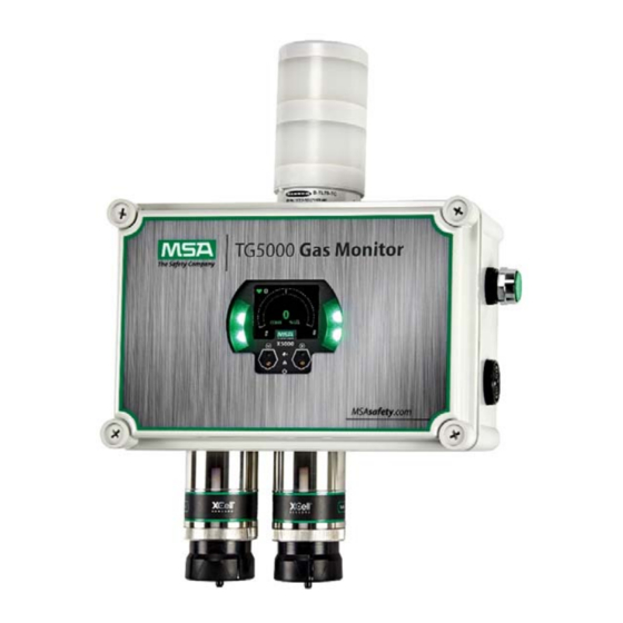
- Page 1 Operating Manual TG5000® Gas Monitor Order No.: 10212126 (L)-Y REV. 0...
- Page 2 1000 Cranberry Woods Drive Cranberry Township, PA 16066 Phone 1-800-MSA-2222 Fax 1-800-967-0398 For your local MSA contacts please go to our website www.MSAsafety.com © MSA 2020. All rights reserved...
-
Page 3: Table Of Contents
Product Installation Check List ......................14 Mounting ............................15 3.3.1 Remote Sensor Mounting Location ....................15 3.3.2 TG5000 Mounting Location ......................15 3.3.3 Remote Sensor Orientation ......................16 3.3.4 Connecting Sensor to Transmitter Housing or Remote Junction Box ..........17 3.3.5 Integrated Mounting Points ...................... - Page 4 Calibration ..............................50 Calibration Equipment ........................50 Calibration Frequency ........................51 Calibration Frequency for XCell Sensors with TruCal and Diffusion Supervision (H S & CO only) 52 Calibration Frequency for XCell Sensors with TruCal without Diffusion Supervision S & CO Only)……………………………………………………………………………………………52 Calibration Types: Zero vs.
-
Page 5: Safety Regulations
WARNING! Read this manual carefully. The TG5000 Gas Monitor is a General Purpose unit and must be installed, operated and maintained in strict accordance with their labels, cautions, warnings, instructions, and within the limitations stated. -
Page 6: Product Warranty
Safety Code 6, obtainable from Health Canada's website www.hc-sc.gc.ca. Product Warranty ITEM WARRANTY PERIOD MSA warrants that this product will be free from mechanical defects and faulty workmanship for the period specified in this table for each component, TG5000 Gas Monitor provided it is maintained and used in accordance with MSA's instructions and/or recommendations. -
Page 7: Description
Fig. 1 OLED Display In addition to the OLED display, the TG5000 also employs green, yellow and red LEDs on the side and lower middle of its face. These are used to signal normal operating conditions, fault conditions and alarm conditions. -
Page 8: No Tool Interface
The TG5000 can be ordered with Bluetooth communication. Using the X/S Connect App on an appropriate smart phone or tablet, you are able to interface with the TG5000 in a larger and more user friendly setting. Connecting via Bluetooth enables communication with transmitter up to 70 feet (21 m) away. -
Page 9: Xcell Sensors Optimized For Fixed Gas Applications
XCell toxic and combustible cat bead sensors are developed and manufactured by MSA. Now optimized for fixed gas applications, the XCell sensor platform is available in the TG5000 and provides multiple benefits, including a standard 3-year warranty on all XCell sensors. -
Page 10: Safeswap
Failure to follow the above warnings can result in serious personal injury or loss of life. Housing The TG5000 comes in a polycarbonate housing with integral mounting holes for 10-32 screws in the enclosure base. The enclosure cover must be removed in order to gain access to the... -
Page 11: Label Overview
Description Label Overview System serial number is located where shown inside the TG5000 lid (highlighted in yellow). Fig. 3 Blank System Serial Number Label Fig. 4 TG5000 - Position of Serial Number Label Located Inside of Lid... - Page 12 Description ATO Code Label Fig. 5 Digital Sensor - Position of Label ATO Code Label Fig. 6 XIR Plus - Position of Label...
-
Page 13: Installation
Do not paint the device. Avoid painting in areas where the TG5000 and remote sensor junction box are located. If painting is required in an area where an TG5000 or remote sensor has been installed, exercise caution to ensure paint is not deposited on the sensor inlet fitting. Paint solvents can also cause an alarm condition to occur or potentially poison electro- chemical sensors. -
Page 14: Installation Warnings - Read Before Installation
Installation Product Installation Check List Before Installation • Review national electrical codes • Review local procedural and building codes • Determine optimum transmitter placement • Determine wire requirements • Determine mounting hardware requirements • Review approvals and ensure suitability for installation Mounting •... -
Page 15: Mounting
3.3.2 TG5000 Mounting Location Mount the TG5000 with the front panel display at or slightly above eye level. View of display must remain unobstructed. -
Page 16: Remote Sensor Orientation
Installation 3.3.3 Sensor Orientation WARNING! Mount the XIR PLUS with the sensor inlet fitting extended horizontally from the junction box (Fig. 7) to prevent the build-up of particulate or liquid matter on the monitor's optical surfaces. Mount the digital sensor with the sensor inlet fitting (Fig. 8) pointed downward; otherwise, the inlet may become clogged with particulate matter or liquids. -
Page 17: Connecting Sensor To Transmitter Housing Or Remote Junction Box
5. If using a second sensor, connect it to the “Sensor 2” position. NOTICE If only using one sensor, and it is connected to “Sensor 2” position, the TG5000 will enter Sensor Missing fault. See Disable Sensor in section 4.2.2 for details on how to clear this fault. - Page 18 6. Verify the sensor connector is firmly seated on the terminal board. 7. Attach the sensor's ground to either of the grounding screws inside the TG5000 back plate. 8. Replace the board stack legs into the four depressions in the mounting plate. Push firmly on the board stack where indicated (see Fig.
-
Page 19: Integrated Mounting Points
Installation 3.3.5 TG5000 Mounting Points The TG5000 transmitter can be mounted with or without any additional brackets using the integrated mounting holes. Clearance holes for 10-32 screws (see Fig. 11A for mounting hole location). Fig. 11A Internal Mounting Holes Fig. 11B Mounting Bracket (Optional) -
Page 20: Installing A Remote Sensor Junction Box
Sensors mounted remotely must use either a XP or GP junction box. Only one sensor can be connected to each junction box. The instructions for connecting the sensor to the TG5000 are outlined in sections 3.3.4. The XP junction box is available in 316 Stainless Steel and the GP junction is available in polycarbonate plastic. -
Page 21: 2" (50.8 Mm) Pipe Mount
The integrated mounting tabs on the remote sensor housing can be mounted to a 2" (50,8 mm) pipe using a standard U-bolt. MSA provides U-bolts as an optional accessory (Part Number 10179873), however any 2” (50.8 mm) pipe U-bolt rated for the weight and dimensions of the housing can be used. -
Page 22: Duct Mount
Installation 3.3.9 XP Remote Sensor Duct Mount Duct mount kits are available for monitoring atmosphere inside flat or round ducts. Round duct mount kits are available for small ducts 12-20" (305-508 mm) in diameter (Part Number 10179124) and large ducts 20-40" (508-1016 mm) in diameter (Part Number 10179321). The flat duct mount (Part Number 10176947) is universal for flat ducts. -
Page 23: Mounting With An Sm5000 Sampling Module
An aspirated (PN 10058101) and a DC pump (PN 10043264) model are available for use with the TG5000 with either digital or XIR sensors. For more information on mounting requirements and use with SM5000 sampling modules, see the SM5000 operating manual(s). -
Page 24: Electrical Power Connections
having jurisdiction and these installation instructions, as applicable. Do not make any connections to the TG5000 main board or junction box input, output, and relay connections while under power. Making connections under power could lead to electrical shock or ignition of a hazardous atmosphere. -
Page 25: Electrical Hardware Requirements
An external Class 2 power supply is required to supply 24 VDC +/- 10% to the TG5000. Incoming power and signal cables should be a braided shield cable such as Alpha Wire 3248 or equivalent. -
Page 26: Instructions For Power And Analog Output
TG5000. Failure to follow the above warning can result in serious personal injury or loss of life. The TG5000 comes wired with AC for the power supply option or wired to terminal blocks (TB1) for the non-power supply option. The red colored (4-pin) connector interfaces power and analog outputs 1 and 2. The HART inter- face is a separate, green colored (2-pin) connector. - Page 27 Note: Sensor connectors come pre-wired on the sensor body. Note: Leaving exposed wire from the connector can electrically short the system. TG5000 without power supply option power and analog output connections. (1) Remove the TG5000 enclosure cover. (2) Use a small, flat head screwdriver to open the power and analog wire entries on the TB1.
- Page 28 Care must be taken to insure the TG5000 label inside overlay surface is free of smudges/dirt and grease. Dirt and grease can interfere with the touch interface of the display.
-
Page 29: Relay And Power Connections
3.4.4 Relay and Power Connections Relay Board Stack Overview The TG5000 Relay pack is configured from the two alarm relays on the PCB board stack. Relays 1 and 2 from the PCB board stack operate the integral strobe, sounder and user relay dry contacts. - Page 30 Relay Specifications WARNING! The TG5000 default relay mapping mode is Common mode and must not be changed. Changing the relay mapping will cause the TG5000 relay pack, horn, horn silence button and installed light stack to not work properly and users may not be alerted to presence of gas.
-
Page 31: Internal Power Supply
If using AC power on the fault relay contacts, the relay wires should not be run within the same conduit or cable tray as the DC power supplied to the TG5000 or the TG5000 junction box connection. A separate wire entry on the device should be used for AC power connected to the relays. -
Page 32: Operation
Startup 4.1.1 Initial Startup The first time the TG5000 is powered on, the analog output defaults to the Maintenance Mode setting (default 3.5 mA) and the following will appear on the display while the LEDs cycle from GREEN, to RED, to AMBER, then to GREEN: •... -
Page 33: Settings
Operation Settings The TG5000 is a tool free transmitter. The two EZ touch buttons on the face of the display can be used to navigate through the menu structure. The buttons are designed for use with fingers with a “press” and “release” action and work best without gloves. -
Page 34: Instrument Settings
Operation 4.2.1 Instrument Settings The following settings are saved to the device memory and will not change if the sensor type is changed. Scroll to Settings. Select Instrument. Select to enter the menu. Setting Default Menu 1 Options Menu 2 Options 3.5mA with HART Analog Settings Custom 1... - Page 35 Operation Setup Relay State for Energized or De-Energized The relay configuration from the factory should not be altered as it will cause undesirable operation of the local strobes, horn and pushbutton. Analog Output Settings for Fault Conditions Analog outputs can be set to 3.5 mA and 1.25 mA with HART, or to custom output values as listed in Tab.
- Page 36 Operation...
- Page 37 As a visual indication, the green LEDs will toggle and quickly flash when a device is paired. Once paired with an TG5000, the user will be able to connect to the same TG5000 remotely and without needing to enter a pairing code, unless over 25 other devices are paired with the same TG5000 afterwards.
- Page 38 The Bluetooth connection is encrypted and secured with a unique six-digit pin that must be confirmed on the mobile device and acknowledged on the detector display. All of the previously paired devices can be erased from the TG5000 to provide additional security and control. To Reset All device pairings: Scroll to Settings.
- Page 39 If a sensor is not reconnected after the 2-minute window, the TG5000 will enter a “Sensor Missing” fault condition. All XCell Sensors have SafeSwap and do not need to be disconnected from power while changing sensors.
- Page 40 Scroll and select Save to confirm password. Language The TG5000 main display can be viewed in multiple languages. Available Languages are: English, French, Spanish, Portuguese, Italian, Dutch, Russian, Chinese, and German. The X/S Connect App is only available in English and does not change when the display language on the TG5000 is changed.
- Page 41 Operation Controller Data Reset Controller Data Reset will reset all of the settings in the main PCBA to their factory defaults and cycle power to the unit. To reset data to factory default values: Scroll to Settings. Select Instrument. Scroll and select Controller Data Reset. Select Continue.
-
Page 42: Sensor Settings
Operation 4.2.2 Sensor Settings The following settings are saved to the TG5000 so that if the sensor is replaced with the same sensor type (gas and range), the settings will remain the same. If a different sensor type and range is used to replace the previous sensor, the new sensor’s default settings will upload to the device. - Page 43 Operation Span Value The span value is used to set the calibration point. The default span values are approximately half of the total range of the sensor as purchased (see Tab. 14). If the range is changed, the span value should also be changed to increase accuracy over the full-scale range.
- Page 44 Operation Gas Table The ULTIMA XIR PLUS combustible sensor can be calibrated to a wide range of compounds, see section 9 for a list of gases, span values, and gas table values. The XIR PLUS sensor is only performance approved for Methane and Propane. Gas Table # Target Gas Methane...
- Page 45 0 mA. By default, the TG5000 has the Sensor 2 position disabled. If at any time a sensor is connected to a position that is disabled, the TG5000 will automatically enable that sensor position.
- Page 46 Operation...
- Page 47 Operation Tab. 14 Default Sensor Settings FS = Full Scale Range. The Range Max value on catalytic bead cannot be set below 20%. Display resolution is not a configurable option Class I Division 2/Zone 2 Only sensors do not have a flame arrestor (aka Frit). Course threads on the sensor assembly and sensor body are used to prevent a customer from installing into a Class I Division 1/Zone 1 sensor body.
- Page 48 Operation Tab. 15 Default Sensor Settings - XIR Plus Sensors Display resolution is not a configurable option...
-
Page 49: Status Menu
Operation Status Menu The following settings can be viewed through Status Menu without a password, regardless of whether one is enabled. Scroll and select Status. Use ↓ to scroll through the list: • Tag # • Software Version • Sensor Type •... -
Page 50: Calibration
Tab. 14 for Default Span Values by Sensor Type. Calibration kits are available from MSA for cali- bration of the TG5000. The kits come housed in a convenient carrying case and contain all items necessary for a complete and accurate calibration, including a regulator, tubing, and Calibration Caps. -
Page 51: Calibration Frequency
Calibration Tab. 16 Calibration Kits Balance Air Balance Nitrogen Flow Rates: CALKIT1 = 1 liter/min CALKIT2 = 0.25 liter/min Calibration Frequency The frequency of calibration gas testing depends on the operating time, chemical exposure, and type of sensor. Especially in new installations or applications, it is recommended that the first sensors be calibrated more often to establish the sensor performance in this particular environ- ment. -
Page 52: Calibration Frequency For Xcell Sensors With Trucal And Diffusion Supervision (H 2 S & Co Only)
Calibration Calibration Frequency for XCell Sensors with TruCal and Diffusion Supervision S & CO only) Sensors with TruCal technology will adjust sensitivity without any manual intervention or calibra- tion, unless called for by the sensor. If the adjusted sensitivity from TruCal deviates too far from the last gas calibration sensitivity, the sensor will recommend or, in extreme cases, require a cali- bration. -
Page 53: Calibration Types: Zero Vs. Span
The XIR Plus sensor can be calibrated to a wide variety of gas compounds using either 0.1 % propane, 0.6 % propane, or 2.5 % methane, and MSA's gas table. See Tab. 21 for a complete list of gas compounds and corresponding tables and span values. -
Page 54: How To Zero Calibrate Xcell Sensors
Calibration How to Zero Calibrate XCell Sensors NOTICE If a password is enabled, you will not be able to proceed with the calibration without the password. To abort, press either button on the touchscreen or mobile application at any time during the zero calibration. -
Page 55: How To Calibrate Xcell Sensor
Calibration How to Calibrate XCell Sensors (See section 5.8 for calibrating oxygen sensors.) NOTICE If a password is enabled, the user will not be able to proceed with the calibration without the pass- word. To abort, press either button on the touchscreen or mobile application before Span Calibration begins. -
Page 56: How To Calibrate An Oxygen Xcell Sensor
5.11 Calibration Confirmation and As Found/As Left Values The TG5000 Gas Monitor records the date of the last successful calibration as well as the As Found/As Left values. This date can then be displayed on the OLED display under the Status... -
Page 57: Maintenance
The TG5000 Gas Monitor is constantly performing a self-check. When a problem is found, it displays the appropriate error message. When a critical error is detected within the device, the 4- 20 mA output signal goes to a fault condition. -
Page 58: Replacing An Xcell Sensor
Failure to follow the above warning can result in serious personal injury or loss of life. Replacing an XCell Sensor The only routine maintenance item is the sensor, which has a limited lifetime. The TG5000 sensors with TruCal technology will indicate when the sensor is near end of life through the Status Menu. - Page 59 The TG5000 Gas Monitor is shipped with the Sensor Swap Delay enabled. This means that the 4-20 mA output signal and the fault relay will hold off a fault indication for two minutes before the missing sensor indication is displayed on the device.
-
Page 60: Clearing A Blockage
Maintenance Clearing a Blockage If using a Digital Sensor with Diffusion Supervision, and if the Diffusion Supervision feature has been enabled in the Sensor Settings, the sensor will notify the user if it detects foreign material obstructing the sintered metal frit where gas would normally enter the sensor (see Fig. 28). When this condition is detected, the transmitter will go into fault and show “Diffusion Supervision Fault”... -
Page 61: Troubleshooting
Maintenance If a sensor is in Diffusion Supervision Fault, the device will still allow the user to attempt to calib- rate the sensor. In the rare event that a sensor calibration is successful, but the Diffusion Super- vision system continues to detect a blockage in the gas path, the Diffusion Supervision Fault will return in approximately 24 hours. - Page 62 Maintenance...
- Page 63 Maintenance...
- Page 64 Maintenance...
- Page 65 Ordering Information Maintenance Tab. 17 Troubleshooting Lower numbers have higher priority...
-
Page 66: Ordering Information
Repair or alteration of the TG5000 Gas Monitor, beyond the scope of the maintenance procedures provided in this manual or by anyone other than authorized MSA service personnel, could cause the product to fail to perform as designed and persons who rely on this product for their safety could sustain serious personal injury or loss of life. -
Page 67: Accessories
ROUND DUCT MOUNT KIT, SMALL, TG5000 10179124 ROUND DUCT MOUNT KIT, LARGE, TG5000 10179321 Pipe Mount Kit, Universal 20-150 MM PIPE MOUNT, TG5000/S5000 10176946 Pipe Mount Kit, 2" U-Bolt 2” PIPE MOUNT KIT, TG5000 10179873 SM5000 SAMPLING MODULE, DC PUMP MODEL 10043264 SM5000... -
Page 68: Appendix: Specifications
Appendix: Specifications Appendix: Specifications TG5000 specifications only, see Ultima X5000 Gas Monitor Manual (P/N 10177361) for TG5000 remote sensor specifications Humidity Range 0-90% RH, Non-Condensing Ambient Temperature Range -20°C To 40°C (-4°F To 104°F) Enclosure Polycarbonate Plastic Power Requirements: TG5000 with power supply... -
Page 69: Appendix: Calibration Guide For Additional Gases
Appendix: Calibration Guide and Additional Gases Appendix: Calibration Guide for Additional Gases The ULTIMA XIR PLUS sensor can be calibrated for a wide variety of combustible gas compounds. This information is only applicable for combustible XIR PLUS sensors and does not apply to CO and acetylene sensors. - Page 70 Appendix: Calibration Guide and Additional Gases...
- Page 71 Appendix: Calibration Guide and Additional Gases (R-32)
- Page 72 Appendix: Calibration Guide and Additional Gases...
- Page 73 Appendix: Calibration Guide and Additional Gases Tab. 21 XIR PLUS Calibration Guide for Additional Gases...
-
Page 74: Appendix: Hart Specific Information
Appendix: HART Specific Information Appendix: HART Specific Information The TG5000 Gas Monitor is available with an optional HART (Highway Addressable Remote Transducer) output communications protocol. With this option, the TG5000 complies with HART Protocol Revision 7. All available status bytes are defined in the X5000 HART Specification found on the product CD. - Page 75 For local MSA contacts, please visit us at MSAsafety.com ...
Need help?
Do you have a question about the TG5000 and is the answer not in the manual?
Questions and answers