
Related Manuals for MSA SMC 5100-IT Series


Summary of Contents for MSA SMC 5100-IT Series
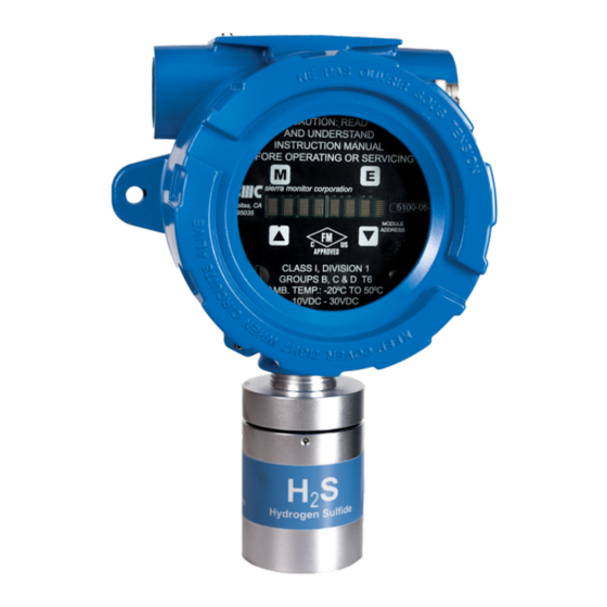
- Page 1 Operating Manual SMC 5100-XX-IT Toxic Gas Detector Module Document No./Revision:T12020/E3 Print Spec: 10000005389 (F) MSAsafety.com...
- Page 2 The warranties made by MSA with respect to the product are voided if the product is not installed and used in accordance with the instructions in this manual. Please protect yourself and your employees by following the instructions.
-
Page 3: Table Of Contents
Contents Product Description General Product Configuration Theory of Operation Modes of Operation 1.4.1 Classic Sentry Interface 1.4.2 Modbus Operation 1.4.3 Analog Operation 1.4.4 Remote Sensor 1.4.5 HART Connection 1.4.6 Remote Alarm Reset 1.4.7 Optional Integral Relays Mechanical 1.5.1 Enclosure 1.5.2 Transmitter Electronics 1.5.3 Sensor Assembly Interconnect Wiring Power Requirements... - Page 4 Main Menu Set-Up Maintenance Sub-Menu Calibration Calibration Frequency Calibration Preparation Calibration Gas Delivery Methods Sensor Exposure to Gas Calibration Sub-Menu 6.5.1 5100-03-IT Oxygen Deficiency 6.5.2 5100-88-IT Carbon Dioxide Service Sensor Module Configuration Enclosure Replacement Transmitter Replacement Sensor Replacement Installation Inspection 7.5.1 Controller Installation 7.5.2 Cabling Installation 7.5.3 Sensor Module Installation...
- Page 5 5100-88-IT Dimensions SMC 5100-XX-IT Toxic Gas Detector Module...
-
Page 6: Product Description
1 Product Description Product Description General The Model 5100-XX-IT Toxic Gas Sensor Module is a smart transmitter and member of the IT Series family and it offers a broad array of features including: • Integral alphanumeric LED display • Up to 180 day calibration frequency •... -
Page 7: Product Configuration
1 Product Description Product Configuration Various module mounting configurations can be implemented without special fixtures. Where applicable, these options are factory configured prior to shipment. Mounting configuration can be selected by the installer or field technician and are fully described in this manual. Sensor must always be oriented downward. Theory of Operation Electrochemical sensors are fuel cell-like devices consisting of an anode, cathode, and electrolyte. -
Page 8: Hart Connection
1 Product Description 1.4.5 HART Connection A HART interface option is available. Refer to Section 13 HART for information. 1.4.6 Remote Alarm Reset An input is available for connection of remote alarm reset. Section 4.5 Module Address Switch provides the wiring termination for connecting the remote alarm reset. - Page 9 1 Product Description Model 5100-05-IT-S1/S2 Toxic Gas Sensor – Stainless Steel Enclosure, Dimensions Model 5100-05-IT-A1/A2 Toxic Gas Sensor – Cast Aluminum Enclosure, Dimensions NOTE: These dimensions are valid for all except 5100-25/26-IT. SMC 5100-XX-IT Toxic Gas Detector Module...
-
Page 10: Transmitter Electronics
1 Product Description 1.5.2 Transmitter Electronics Electronic Assembly consisting of one printed circuit board assembly mounted under a cover plate, plugged into one field termination board. Connectors for wiring for power, signal interface and alarm relays are located on the bottom of the termination board. -
Page 11: Cautions & Warnings
2 Cautions & Warnings Cautions & Warnings Introduction Although the IT Transmitter Modules are designed and constructed for installation and operation in industrial applications including “hostile” environments, caution should be taken to ensure that the installation is made in compliance with this instruction manual and that certain procedures and conditions are avoided. -
Page 12: Quick Start
3 Quick Start Quick Start Overview The gas sensor module has been supplied factory calibrated and ready for immediate installation and operation. An installer familiar with installation and operation of gas detection products can use this section to begin immediate use of the module. Wiring See Section 4.2 Wiring... -
Page 13: Installation
4 Installation Installation Sensor Module Locations Model Gas Gas Density 1.00 5100-04-IT CO 0.97 5100-05-IT H 1.19 5100-06-IT Cl 2.49 5100-08-IT ClO 3.09 5100-10-IT SO 2.26 5100-12-IT NO 2.12 5100-25-IT NH 0.60 5100-26-IT HF 1.86 5100-88-IT CO 1.53 NOTE: All IT modules are factory pre-configured and calibrated. All modules are tagged to indicate the configuration including the sensor module number Identify all components during unpacking and install using the factory configuration. -
Page 14: Wiring
4 Installation Wiring 4.2.1 Analog 4-20 mA Operation For a 3-wire non-isolated connection, set jumpers, located on the bottom of the transmitter board, to the lower position as illustrated in Section 4.5 Module Address Switch. Verify that both jumpers are in the position marked by 3-wire. When using a 3-wire connection, a minimum of an 18 AWG, 3-conductor shielded cable must be used. -
Page 15: General
4 Installation 4.2.4 General Install conduit as required by local code or construction specifications. Provide for splice boxes where multiple modules will be wired to a single run. Pull conductors of the correct gauge wire from the controller to each splice box and from the respective splice box to each planned module location. -
Page 16: Transmitter And Sensor Installation
4 Installation Transmitter and Sensor Installation When all pre-wire is complete: 1. Install sensor assembly in the open hub on the module enclosure. The sensor assembly thread must be fully seated into the hub and tightened to maintain explosion proof assembly. 2. - Page 17 4 Installation PCB Label Function Low Alarm Relay NC WARNING Low Alarm Relay COM Low Alarm Relay NO High Alarm Relay NC ALARM High Alarm Relay COM High Alarm Relay NO Trouble Alarm Relay NC TRBL** Trouble Alarm Relay COM Trouble Alarm Relay NO * P4 Connections are installed only when the optional Relays are included ** Trouble relay is a fail-safe so it is energized for normal operation, functions are labeled for normal operation.
-
Page 18: Module Address Switch
4 Installation Module Address Switch For digital interface applications the module address switch (or Modbus node) must be set per the table below. Position Address Position Address Sensor 1 Sensor 09 Sensor 2 Sensor 10 Sensor 3 Sensor 11 Sensor 4 Sensor 12 Sensor 5 Sensor 13... - Page 19 4 Installation Interface Board Connectors RS-485 – Termination, BIAS Jumper SMC 5100-XX-IT Toxic Gas Detector Module...
- Page 20 4 Installation mA Circuit Types SMC 5100-XX-IT Toxic Gas Detector Module...
- Page 21 4 Installation 4-20 mA Circuit Type Connections for 5100-XX-IT SMC 5100-XX-IT Toxic Gas Detector Module...
- Page 22 4 Installation Wiring Connections for Modbus and Sentry Interface 5100-XX-IT TO SENTRY (dry contact only unpowered) 5100-XX-IT TO MODBUS DEVICE SMC 5100-XX-IT Toxic Gas Detector Module...
- Page 23 4 Installation Wiring Connections for Remote Alarm Reset 5100-XX-IT Remote Alarm Reset (Unsupervised) (dry contact only unpowered) 5100-XX-IT Remote Alarm Reset (Supervised) SMC 5100-XX-IT Toxic Gas Detector Module...
-
Page 24: Operation
5 Operation Operation Introduction The Gas Sensor Module utilizes a visual menu system operated by means of a magnet. A magnetic tool (5358-50) is supplied for this purpose. The menu system is used to configure alarm set-points, calibrate the sensor module, and for maintenance procedures and alarms acknowledge. -
Page 25: Main Menu
5 Operation Main Menu Function Display Description Reference Mode Switch [M] Enter Switch [E] Switch [▲] Previous Menu Down Switch [▼] Next Menu 5100-XX First screen at power up: Model No. VXX-XX-- Second screen at power up: Version No. Third screen at start up, will remain for 60 STARTING seconds XXX PPM... - Page 26 5 Operation The table below defines the key operational displays on the operator interface. Display Description STARTING Delay from loss of power at start-up XXX PPM Concentration LXXX PPM Low Alarm (Warning) HXXX PPM High Alarm (Alarm) HIGH Measures gas, concentration exceeds 100% of Full Scale CXXX PPM Calibration Mode Acknowledged Function NOTE: If display shows “Start”...
-
Page 27: Set-Up
5 Operation Set-Up The sensor module set-points menu is used to initially set-up the alarm set points, relay actions, gas type and range, 4-20 mA action or RS-485/Sentry address and baud rates, Digital Input and Warm-up time. Use the [▲] or [▼] keys to select following menus and press [E] to select. ... - Page 28 5 Operation • 4-20mA – Use the [▲] or [▼] keys to select Calib or CalibOut menu and press [E]. The “Calib” section of the menu allows the user to calibrate the 4 mA and 20 mA outputs. To calibrate the 4 mA and 20 mA outputs it is necessary to have an amp meter connected to the 5100-XX-IT and upon selecting the 4 mA output calibration then the [▲] or [▼] keys can be used to adjust the 4 mA reading on the amp meter until it reads 4 mA.
- Page 29 5 Operation Function Display Description Reference Down *Sentry Low Alarm Relay set to Sentry Gas Range Adjustment Example Enter Range S.P. Function - Range Adjust Enter *100 PPM Select [E] to select or ▲ or ▼ to select another and press [E] Down 10 PPM Press [E] if selecting 0-10 PPM range...
-
Page 30: Maintenance Sub-Menu
5 Operation Maintenance Sub-Menu The maintenance menu enables the operator to view sensor and software versions. MSA Safety technical support has access to other values as needed. The maintenance menu operation is described in the table below. Function Display Description... - Page 31 5 Operation The hardware diagnostic options (“HW Diag”) are listed below. Press the [E] key to select any of the sub-menus. Function Display Description Reference Unlock SW Diag Software diagnostics sub-menu. sequence HW Diag Hardware diagnostics sub-menu. Enter TempSnsr Displays the temperature of sensor assembly in °F. Test WDT Tests function of internal watchdog.
-
Page 32: Calibration
6 Calibration Calibration Calibration Frequency The Gas Sensor Module has been calibrated in the factory prior to shipment. It is recommended that the user calibrate before placing into service. The sensor module must be calibrated every 180 days at a minimum. Periodic functional tests are advisable for critical applications and hostile environments. -
Page 33: Sensor Exposure To Gas
6 Calibration Sensor Exposure to Gas Calibration gas must be delivered to the sensor using the flow rate and duration listed below: Model Calibration Gas Flow Period 5100-03-IT Air 300 cc of Zero Air or exposure to Ambient Air (3 minutes) 5100-04-IT Carbon Monoxide 300 cc/min Until Stable (minimum 3 minutes) 5100-05-IT Hydrogen Sulfide 300 cc/min... -
Page 34: 5100-03-It Oxygen Deficiency
6 Calibration Function Display Description Reference C 25PPM Operation: Apply calibration gas Enter CAL-FAIL Operation: No calibration gas applied, or sensor did not respond correctly. WAIT-300 Operation: Five minute time out before sensor is returned to service. Mode (Any) Operation: Hold magnet over Mode Switch for ten seconds to abort calibration Sub C Banner: ... -
Page 35: Service
7 Service Service Sensor Module Configuration The gas sensor module is comprised of the following sub-assemblies: 5100-XX-IT Gas Sensor Module (See Section 9 Parts List) SPL21810 Aluminum Enclosure SPL21823 316SS Enclosure XXXXXXX Transmitter Assembly (See Section 9 Parts List) XXXXXXX Sensor Assembly (See Section 9 Parts List) 5200-XX-IT Sensor (See Section... -
Page 36: Transmitter Replacement
7 Service Transmitter Replacement The transmitter assembly should be replaced when it is determined that it is unreliable, noisy or cannot be adjusted for calibration. This may occur due to age, corrosion or failed components. To replace the transmitter assembly: 1. -
Page 37: Installation Inspection
7 Service Installation Inspection Prior to system start-up or trouble shooting, the entire system should be visually inspected. The following are guidelines for that inspection. 7.5.1 Controller Installation • Controller installed in conformance to instruction manual recommendations. • AC power is correctly grounded. •... -
Page 38: Module Displays "Starting" For More Than 1 Hour
7 Service 7.6.1 Module Displays “Starting” for more than 1 Hour 1. Make sure the sensor is placed in an ambient room temperature environment. 2. Power cycle the sensor. 3. Ensure that the sensor is not exposed to gas of interest during warm-up. 7.6.2 Module Does Not Display the Correct %PPM 1. -
Page 39: Error Messages
7 Service 7.6.10Error Messages LED Display LED Display Description (Ver 3.05 and earlier) (Ver 3.07 & later) NO SENSR NO SENSR Unable to detect sensor assembly Err: 0x02 DIG INP! Digital Input status Err: 0x20 SNS RNGE Sensor ADC readings out of range Err: 0x40 SNS FAIL Too many 1-wire communication errors... -
Page 40: Specifications
8 Specifications Specifications Sensor Type Electrochemical Sensor Standard Optional Zero Response Repeatability Linearity Resolution Accuracy Range Max Range Drift Time Life 5100-03-IT O 5-25% Vol 0-25% Vol +/- 0.1% +/- 0.2% +/- 0.2% +/- 0.1% <10 sec. +/- 0.2% 2 years 5100-04-IT CO 0-500 PPM 1200 PPM... - Page 41 8 Specifications Input Remote Alarm Reset Normally open digital input Power Power consumption 2 watts (4 watts for 5100-88-IT) Input voltage 24 VDC nominal: 10-30 VDC Operating Range Ambient Temp (°F) Ambient Temp (°C) Relative Humidity 5100-03-IT O -4 to 122 °F -20 to 50 °C 15 –...
- Page 42 8 Specifications Performance Approvals 5100-05-IT Only FM Performance Approval FM Performance Approval CE Mark Remote Sensor Option (Section 11 Remote Sensor Drawing) Distance between sensor and transmitter 5100-03-IT 10 feet 5100-06-IT 10 feet 5100-04-IT 15 feet 5100-08-IT 10 feet 5100-05-IT 15 feet 5100-10-IT 15 feet...
- Page 43 8 Specifications Cross Sensitivity Data 5100-04-IT Carbon Monoxide 5100-12-IT Nitrogen Dioxide Conc. Response Conc. Response 15 PPM ~38 PPM 300 PPM 0 PPM 5 PPM ~3 PPM 15 PPM -1.5 to 0 PPM 35 PPM ~10 PPM 5 PPM -0.05 to 0 PPM 5 PPM ~-3 PPM 35 PPM...
- Page 44 8 Specifications 5100-10-IT Sulfur Dioxide Conc. Response 15 PPM 0 PPM 35 PPM -7 to 0 PPM 5 PPM -5 PPM 5 PPM -1.5 to 0 PPM 5 PPM ~5 PPM 100 PPM 0 PPM HCN 10 PPM <5 PPM 5 PPM 0 PPM C2H4 100 PPM 0 PPM...
-
Page 45: Parts List
9 Parts List Parts List Options 5311-00 Rainshield 5311-02 Rainshield with calibration port Calibration Items 1250-01 Gas Sensor Calibration Kit, Type A (CO, H2S, Air) 1250-03 Gas Sensor Calibration Kit, Type C (Cl2) 1250-04 Gas Sensor Calibration Kit, Type A 1260-00 Gas Cylinder, Air, (Type A) 1260-04... - Page 46 9 Parts List Spare Parts 5200-03-IT Sensor, for 5100-03-IT 5200-04-IT Sensor, for 5100-04-IT 5200-05-IT Sensor, for 5100-05-IT 5200-06-IT Sensor, for 5100-06-IT / 5100-08-IT 5200-10-IT Sensor, for 5100-10-IT 5200-12-IT Sensor, for 5100-12-IT 5200-21-IT Sensor, for 5100-21-IT SPL21834 Sensor Assembly, Aluminum, for 5100-03-IT - Oxygen SPL21832 Sensor Assembly, Aluminum, for 5100-04-IT - CO SPL21830...
-
Page 47: Limited Warranty
Limited Warranty MSA Safety warrants its products to be free from defects in workmanship or material under normal use and service for two years after date of shipment. MSA Safety will repair or replace without charge any equipment found to be defective during the warranty period. -
Page 48: Remote Sensor Drawing
11 Remote Sensor Drawing Remote Sensor Drawing NOTE: Drawing using aluminum enclosure. Unless otherwise specified, NOTE the following: Provide access for sensor replacement during installation. For field upgrade, relocate 5100-XX-IT-A1/A2 Sensor to 5394-52 as shown in Detail A (in image above). Use belden cable #9925 (see in image above). - Page 49 11 Remote Sensor Drawing Typical Wire Connections at all Terminations: Color Position Black White Bare Wire 4 SMC 5100-XX-IT Toxic Gas Detector Module...
-
Page 50: Modbus Memory Map
12 Modbus Memory Map Modbus Memory Map SMC 5100-XX-IT Toxic Gas Detector Module... -
Page 51: Hart
13 HART HART SMC 5100-XX-IT Toxic Gas Detector Module... - Page 52 13 HART SMC 5100-XX-IT Toxic Gas Detector Module...
- Page 53 13 HART Hart Protocol Menu HART (Highway Addressable Remote Transducer) Protocol is the global standard for sending and receiving digital information across analog wires between smart devices and control or monitoring system. HART is a bi-directional communication protocol that provides data access between intelligent field instruments and host systems. A host can be any software application from technician's hand-held device or laptop to a plant's process control, asset management, safety or other system using any control platform.
- Page 54 13 HART Device Specific Commands Summary Command Number Description Key Press Write Device Values (using index) Read Device Values (using index) Set Alarm Relay Action Set Warning Relay Action Reset Alarms Abort Calibration RESERVED Apply ZERO Gas Apply SPAN Gas RESERVED RESERVED RESERVED...
- Page 55 13 HART Command 131: Set Alarm Level Used to set the following internal device parameters (variables), with appropriate index. Reading of these parameters is achieved using Command 132. Index Parameter Read/Write Alarm Level Setpoint Warning Level Setpoint Calibration Gas Value Force Gas Value Maximum Gas Value Read...
- Page 56 13 HART Command 133: Set Alarm Relay Action Set the action/mode of the Alarm Relay. Request Data Bytes: Byte Format Description 0=Latching (default) Unsigned-8 1=Sentry 2=Non-Latching Command Specific Response Data Bytes: Byte Format Description Unsigned-8 Response Code Unsigned-8 Device Status Unsigned-8 Returns new value of Alarm Relay Action Variable Command 134: Set Warning Relay Action Set the action/mode of the Warning Relay.
- Page 57 13 HART Command 135: Reset Alarms This command will reset any alarm relays that have been latched, providing the alarm condition is no longer present on the sensor. Request Data Bytes: None Response Data Bytes: Byte Format Description Unsigned-8 Response Code Unsigned-8 Device Status Command 136: Abort Calibration This command aborts the calibration procedure.
- Page 58 13 HART Command 139: Apply SPAN Gas This command will signal the module to accept the present sensor output to as the SPAN gas condition. Request Data Bytes: None Response Data Bytes: Byte Format Description Unsigned-8 Response Code Unsigned-8 Device Status Command 141: Force Gas Value Request Data Bytes: Byte...
- Page 59 13 HART Command 144: Set Transducer Serial Number This command allows user to add a device specific serial number, if required. This is different from the serial number assigned by the Manufacturer. Request Data Bytes: Byte Format Description Unsigned-24 Serial Number Response Data Bytes: Byte Format...
- Page 60 13 HART Command 147: Trim 4mA Loop This command allows initiation of the 4mA trimming procedure. Request Data Bytes: None Response Data Bytes: Byte Format Description Unsigned-8 Response Code Unsigned-8 Device Status Command 148: Trim 20mA Loop This command allows initiation of the 20mA trimming procedure. Request Data Bytes: None Response Data Bytes: Byte...
- Page 61 13 HART Command 150: Write MODBUS RTU 16-bit Register (using index) This command allows the writing to the sensor module 16-bit MODBUS registers as defined in the MODBUS RTU register map. The index provided is 1 byte and is referenced from address 40000. The unsigned 16-bit data that is written is provided in floating point format.
-
Page 62: Gas Sensor Module Calibration
14 Gas Sensor Module Calibration Gas Sensor Module Calibration 14.1 Calibration for 5100-25-IT NOTE: Supplement to Instructions in Section Calibration. 1. Equipment Required The following tools and equipment will be required for calibration: • Use 1250-04 Calibrator Kit ◦ 1260-25 Amonia Cylinder ◦... - Page 63 14 Gas Sensor Module Calibration 6. Electrolyte Replacement a. Invert the sensor assembly so that the membrane is upward. b. Insert the sensor assembly in a clamp, if available, and unscrew the box nut counterclockwise, and take out the hold-down ring, membrane and O-Ring. Then pour out the old electrolyte into a beaker for disposal. CAUTION: Avoid contact of the electrolyte with skin, eyes and clothing.
- Page 64 14 Gas Sensor Module Calibration Spare Parts SPX27057 Recharge Kit NH3 SPX27061 Recharge Kit HF SPX57009 Membrane Kit (both) SPX99017 Electrolyte NH3 SPX99018 Electrolyte HF 5200-25-IT Sensor Assy NH3 5200-26-IT Sensor Assy HF SMC 5100-XX-IT Toxic Gas Detector Module...
- Page 65 14 Gas Sensor Module Calibration Model SMC 5100-25-IT-A1/A2 and Model SMC 5100-26-IT-A1/A2 Model 5100-25-IT-S1 and Model 5100-26-IT-S1 SMC 5100-XX-IT Toxic Gas Detector Module...
-
Page 66: Calibration For 5100-26-It
14 Gas Sensor Module Calibration 14.2 Calibration for 5100-26-IT NOTE: Supplement to Instructions in Section Calibration. 1. The calibration of the Model # 5100-26-IT HF gas sensor module is accomplished by using a 10 ppm Chlorine standard (Type C kit with # 1260-06 cylinder). Scale range is 0-10 ppm with 5 ppm being mid-scale. 10 ppm Cl2 is equivalent to 10 ppm HF. - Page 67 15 5100-88-IT Dimensions 5100-88-IT Dimensions SMC 5100-XX-IT Toxic Gas Detector Module...
Need help?
Do you have a question about the SMC 5100-IT Series and is the answer not in the manual?
Questions and answers