
Subscribe to Our Youtube Channel
Related Manuals for Ruijie Reyee RG-NBF6002M


Summary of Contents for Ruijie Reyee RG-NBF6002M
- Page 1 Ruijie Reyee RG-NBF6002M e-Lighten Core Switch Installation Guide Document Version: V1.0 Date: July 8, 2024 Copyright © 2024 Ruijie Networks...
- Page 2 Ruijie Networks reserves the right to modify the content of the document without any notice or prompt. This manual is designed merely as a user guide. Ruijie Networks has tried its best to ensure the accuracy and reliability of the content when compiling this manual, but it does not guarantee that the content of the manual is completely free of errors or omissions, and all the information in this manual does not constitute any explicit or implicit warranties.
-
Page 3: Preface
Intended Audience This document is intended for: Network engineers Technical support and servicing engineers Network administrators Technical Support The official website of Ruijie Reyee: https://reyee.ruijie.com Technical Support Website: https://reyee.ruijie.com/en-global/support Case Portal: https://www.ruijienetworks.com/support/caseportal Community: https://community.ruijienetworks.com... - Page 4 Note This manual provides installation steps, troubleshooting, technical specifications, and usage guidelines for cables and connectors. It is intended for users who want to understand the above and have extensive experience in network deployment and management, and assume that users are familiar with related terms and concepts.
-
Page 5: Table Of Contents
Contents Preface ..............................I 1 Overview ............................1 1.1 About the RG-NBF6002M ......................1 1.2 RG-NBF6002M .......................... 2 1.2.1 Package Contents ......................2 1.2.2 Product Appearance ...................... 3 1.2.3 Hardware Specifications ....................4 1.2.4 Cooling ........................... 6 1.3 Power Module ..........................7 1.3.1 Product Appearance ...................... - Page 6 2.2.1 Floor Loading ....................... 17 2.2.2 Airflow ........................... 17 2.2.3 Space ........................... 17 2.2.4 Temperature and Humidity ................... 17 2.2.5 Cleanliness ........................18 2.2.6 Grounding ........................19 2.2.7 Anti-Electromagnetic Interference................19 2.2.8 Surge Protection ......................19 2.2.9 EMI ..........................20 2.2.10 Installation Site ......................
- Page 7 3.5 Connecting the Power Cable ....................29 3.6 Checklist After Installation ....................... 29 4 Log In to the Web Interface ......................30 5 Troubleshooting ..........................31 5.1 Troubleshooting Flowchart ...................... 31 5.1 Common Faults ........................31 6 Appendix ............................33 6.1 Ports, Connectors, and Media ....................
-
Page 8: Overview
Figure 1-1 Topology Diagram of Reyee e-Lighten Solution The RG-NBF6002M switch, a core switch (OLT) launched by Ruijie Reyee, is designed for passive all-optical local area networks (LANs). It features an innovative management architecture and is compact, fitting two line cards within a 1U chassis. -
Page 9: Rg-Nbf6002M
Installation Guide Overview Model Description Remarks can be configured on MF6000M-16GT8SFP2XS Line card, purchased separately the switch. MF6000M-16FS8GT2XS Line card, purchased separately Supports 1+1 RG-PA150I-FS Power module, purchased separately redundancy RG-NBF6002M 1.2.1 Package Contents Note The package contents are subject to the purchase contract, and actual delivery may vary. Please check the items carefully against the package contents or purchase contract. -
Page 10: Product Appearance
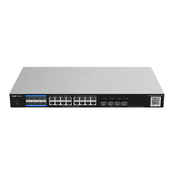
Installation Guide Overview 1.2.2 Product Appearance Figure 1-2 Front Panel of the RG-NBF6002M (with MF6000M-24GT2XS and MF6000M-16GT8SFP2XS Line Cards) Item Description Line card slot 1 For installing a line card. Line card slot 1 For installing a line card. Label Located at the bottom of the device. -
Page 11: Hardware Specifications
Blinking green (slow blinking: on for 2s and off for 0.25s): The device is not connected to Ruijie Cloud. Blinking yellow (on for 1s and off for 1s): The device temperature reaches the warning threshold; the temperature cannot be read; there is another non-critical problem;... - Page 12 Installation Guide Overview SDRAM DDRIII 1 GB Number of Line Card Slots MF6000M-24GT2XS Line Cards MF6000M -16GT8SFP2XS MF6000M-16FS8GT2XS Hot Swapping Supported by power modules, but not by line cards. Power Module RG-PA150I-FS: 100 V AC to 240 V AC, 150 W Power Module Supported.
-
Page 13: Cooling
The switch has a built-in lithium battery to keep the real-time clock running when external power source is unavailable. To replace the lithium battery, please contact Ruijie Networks Customer Service Technical Support to have it replaced with a lithium battery of the same specifications. -
Page 14: Power Module
Installation Guide Overview Power Module 1.3.1 Product Appearance Figure 1-4 Appearance of the RG-PA150I-FS 1.3.2 Hardware Specifications Table 1-3 Hardware Specifications of the RG-PA150I-FS Model RG-PA150I-FS Rated Voltage 100 V to 240 V AC; 50 Hz to 60 Hz Range Maximum Voltage 90 V to 264 V AC;... -
Page 15: Line Card
Installation Guide Overview Line Card 1.4.1 Package Contents Note This package contents applies to all line cards. The package contents are subject to the purchase contract, and actual delivery may vary. Please check the items carefully against the package contents or purchase contract. If you have any questions, please contact your distributor. - Page 16 Installation Guide Overview Component Description run properly. RJ45 port 24 x 10/100/1000BASE-T ports, with RJ45 connectors. RJ45 port LED 24 x 10/100/1000BASE-T port status LEDs. Solid green: A link is set up on the port at a rate of 1000 Mbps. Blinking green: A link is set up on the port at a rate of 1000 Mbps, and data is transmitted on the link.
- Page 17 Installation Guide Overview Component Description RJ45 port 16 x 10/100/1000BASE-T ports, with RJ45 connectors. RJ45 port LED 16 x 10/100/1000BASE-T port status LEDs. Solid green: A link is set up on the port at a rate of 1000 Mbps. Blinking green: A link is set up on the port at a rate of 1000 Mbps, and data is transmitted on the link.
- Page 18 Installation Guide Overview Component Description Blinking green (medium frequency: on for 0.25s and off for 0.25s, repeated): The line card is resetting. Blinking green (medium frequency: on for 0.0625s and off for 0.0625s, repeated) with red system LED: A line card conflict or hot swapping has occurred.
-
Page 19: Hardware Specifications
SFP and SFP+ Transceiver Modules Copper cables are not supported. Transceiver and The supported optical transceiver types may update without prior notification. Cable Types Please contact Ruijie Networks for details. System LED SYS LED and Link/ACT LED Hot Swapping Not supported Power Consumption <... - Page 20 SFP and SFP+ Transceiver Modules. Copper cables are not supported. Transceiver and The supported module types may update without prior notification. Please Cable Types contact Ruijie Networks for details. System LED SYS LED and Link/ACT LED Hot Swapping Not supported Power Consumption <...
- Page 21 SFP and SFP+ Transceiver Modules. Copper cables are not supported. Transceiver and The supported module types may update without prior notification. Please Cable Types contact Ruijie Networks for details. System LED SYS LED and Link/ACT LED Hot Swapping Not supported Power Consumption <...
-
Page 22: Preparing For Installation
Installation Guide Preparing for Installation Preparing for Installation Safety Guidelines Note To avoid personal injury or equipment damage, review the safety guidelines in this chapter before you begin the installation. The following safety guidelines may not include all the potentially hazardous situations. 2.1.1 General Precautions ... -
Page 23: Preventing Esd Damage
Installation Guide Preparing for Installation Locate the emergency power supply switch in the room before installation. In the case of an accident, cut off the power supply immediately. Carefully inspect the equipment and the environment before powering on or off the equipment. ... -
Page 24: Site Requirements
Installation Guide Preparing for Installation a dust cap to keep out dust and prevent it from burning your eyes. When an optical transceiver is in operation, do not look into its port after removing the optical fiber. Doing so may result in eye injury. -
Page 25: Cleanliness
Installation Guide Preparing for Installation electricity generation. This static electricity can pose a danger to the circuits inside the equipment. In a dry environment, static electricity is prone to occur and damage the internal circuits of the equipment. High temperature environments can be detrimental to the equipment, leading to reduced performance and a shorter service life. -
Page 26: Grounding
Installation Guide Preparing for Installation 2.2.6 Grounding A proper grounding system is crucial for ensuring stable and reliable operation of the equipment, as well as preventing lightning strikes and interference. To ensure proper grounding, carefully check the grounding conditions at the installation site according to the grounding specifications, and complete grounding properly based on the actual situation. -
Page 27: Emi
Installation Guide Preparing for Installation power strip, and then connect the equipment to the lightning protection power strip. This prevents high- voltage lightning from directly passing through the equipment over the mains supply AC power cord. Note The lightning protection power strip is not delivered with the equipment. Purchase it as required. ... -
Page 28: Tools
Installation Guide Preparing for Installation Figure 2-2 19-Inch Rack (3) The square-hole rack post is at least 180 mm (7.09 in.) from the front door, and the front door is at most 25 mm (0.98 in.) thick. This ensures an available clearance of at least 155 mm (6.10 in.). The rack depth (distance between front and rear doors) is at least 1000 mm (39.37 in.). -
Page 29: Installing The Device
Installation Guide Installing the Device Installing the Device Caution Before installing the device, ensure that guidelines and requirements in Chapter 2 have been met. Installation Precautions Pay attention to the following points during installation: Connect the power cords of different colors to the corresponding cable terminals. ... -
Page 30: Installing And Removing A Power Module
Installation Guide Installing the Device (2) Place the device horizontally in the rack, and secure it to the rack using the M6 screws and cage nuts (customer supplied). Installing and Removing a Power Module 3.3.1 Installing a Power Module (1) Unpack the power module, and verify that the power input specifications meet requirements. -
Page 31: Removing A Power Module
Installation Guide Installing the Device (2) Remove the power supply slot faceplate. The plane with the power module label is the top side. Hold the handle of the power module with one hand and hold the bottom of the power module with the other hand. Slowly insert the power module along the guide rail until it is fully inserted into the chassis and you hear a click. -
Page 32: Installing And Removing A Line Card
Installation Guide Installing the Device Figure 3-2 Removing the RG-PA150I-FS Power Module Warning Before removing the power module, make sure that the power cord of the corresponding power module is not connected to the power outlet of the power module. Otherwise, it may cause electric shock to the operator or damage the device. - Page 33 Installation Guide Installing the Device 1. Select a Line Card Slot Line cards can be installed in any line card slot of the device. If you want to replace a line card or install an existing line card in another line card slot, you need to reset the device first. Before installing a line card, remove the faceplate of the corresponding slot.
-
Page 34: Removing A Line Card
Installation Guide Installing the Device Installing the RG-NBF6002M Line Card — 2 Figure 3-4 Warning When performing steps (2), (3), and (4), apply a gentle force and insert the line card smoothly. If it is difficult to push the line card, do not apply too much force. Instead, remove the line card and check whether the line card is aligned with the opening edge of the line card slot on the front panel of the device before proceeding. -
Page 35: Troubleshooting A Line Card
Installation Guide Installing the Device Figure 3-5 Removing the RG-NBF6002M Line Card Caution Line cards do not support hot swapping. Before removing a line card, power off the device first. After the line card is removed, if you do not need to install a new line card, install a faceplate to prevent dust from entering and to ensure normal ventilation of the device. -
Page 36: Connecting The Power Cable
Installation Guide Installing the Device During device installation, connect the grounding cable first and disconnect it last. The cross-sectional area of a protective grounding cable should be at least 2.5 mm (12 AWG). A proper grounding system is crucial for ensuring stable and reliable operation, as well as preventing lightning strikes and interference. -
Page 37: Log In To The Web Interface
Installation Guide Log In to the Web Interface Log In to the Web Interface (1) Connect your PC to the MGMT port of the device using an Ethernet cable, as shown in the following figure. Figure 4-1 Setting Up the Configuration Environment (2) Configure your PC with an IP address on the network of 10.44.77.XXX (Range: 1-255, excluding 200). -
Page 38: Troubleshooting
The device is not working properly Check the device installation Check the power connection Check the LEDs status of the device Check the cable connection Contact technical support of Ruijie Networks Common Faults Fault Symptom Possible Cause Solution Press and hold the reset button for over five... - Page 39 Installation Guide Troubleshooting and does not use the same work mode as the interconnected switch. The receiving and transmitting ends are connected incorrectly. Exchange the transmitting and receiving The types of the interconnected ends of the optical cable. optical transceivers do not match. Replace the optical transceiver with another The optical cable type does not one of the same type.
-
Page 40: Appendix
Installation Guide Appendix Appendix Ports, Connectors, and Media 6.1.1 1000BASE-T/100BASE-TX/10BASE-T Ports 1000BASE-T/100BASE-TX/10BASE-T ports are Ethernet ports with auto-negotiation of three speeds: 10 Mbps, 100 Mbps, and 1000 Mbps. They supports auto MDI/MDIX Crossover, and use RJ 45 connectors. Compliant with the IEEE 802.3ab standard, a 1000BASE-T port requires 100-ohm Category 5 or 5e unshielded twisted pair (UTP) or shielded twisted pair (STP) (recommended) cables, and supports a maximum distance of 100 meters (328 feet). -
Page 41: Sfp Ports And Sfp+ Ports
PON Ports and SC Ports Figure 6-4 shows the PON ports and SC ports on equipment in Ruijie Reyee e-Lighten Optical Solution. PON ports on the OLT require e-Lighten optical transceivers with SC connectors, which are connected to an optical splitter using single-mode pigtails. -
Page 42: Sfp And Sfp+ Transceiver Modules
Installation Guide Appendix Description SC connector Single-mode pigtail SFP and SFP+ Transceiver Modules We provide SFP and SFP+ transceiver modules according to the port types. You can select the module to suit your specific needs. An SFP transceiver module can be a 1GE optical transceiver or Ethernet transceiver (Mini- GBIC-GT), while an SFP+ transceiver module is a 10GE optical transceiver. - Page 43 Installation Guide Appendix Transmit Receive Power Optical Wavelength Power (dBm) (dBm) Model Cable (nm) (Yes/No) Type Min. Max. Min. Max. –9.5 –3 –20 –3 SFP-SM1310 1310 –9.5 –3 –17 GE-SFP-ZX –9.5 –3 –17 GE-SX-MM850 –9 –3 –20 –3 GE-LX-SM1310 1310 –9 –3 –20...
- Page 44 Installation Guide Appendix Core Connector Optical Cable Max. Cabling Model Specifications Type Type Distance (μm) SFP-SM1310 9/125 10 km (32,808.4 ft.) GE-SFP-ZX 50/125 550 m (1804.46 ft.) GE-SX-MM850 50/125 550 m (1804.46 ft.) GE-LX-SM1310 9/125 10 km (32,808.4 ft.) SFP-S4-R1000P1 v1 9/125 10 km (32,808.4 ft.) RJ45...
-
Page 45: Sfp+ Transceiver Modules
Installation Guide Appendix Caution The BIDI modules must be used in pairs. For example, if you install the GE-SFP-LX20-SM1310-BIDI on one end, you must install the GE-SFP-LX20-SM1550-BIDI on the other end. 6.2.2 SFP+ Transceiver Modules Table 6-5 Models and Specifications of SFP+ Optical Transceiver Modules Transmit Power Receive Power Optical Cable... - Page 46 SFP+ module types and models are subject to change without prior notice. For any updates about the optical transceivers, contact Ruijie Networks marketing or technical support personnel. The DDM function of AOC cables does not report the transmit power. The transmit power is displayed as...
- Page 47 Installation Guide Appendix Table 6-7 SFP+ Module Cabling Specifications Model Connector Optical Core Modal Max. Cabling Cable Specifications Bandwidth Distance Type (μm) Type (MHz·km) 300 m (984.25 XG-SFP-SR-MM850 50/125 2000 (OM3) ft.) 300 m (984.25 XG-SR-MM850 50/125 2000 (OM3) ft.) 300 m (984.25 SFP+MM850 50/125...
-
Page 48: Surge Protection
Installation Guide Appendix Model Connector Optical Core Modal Max. Cabling Cable Specifications Bandwidth Distance Type (μm) Type (MHz·km) 300 m (984.25 XG-SFP-SR-MM850-I 50/125 2000 (OM3) ft.) 10 km XG-SFP-LR-SM1310-I 9/125 (32,808.4 ft.) Table 6-8 Models and Specifications of e-Lighten Optical Transceivers Transmit Receive Power Optical Cable... - Page 49 Installation Guide Appendix Figure 6-6 Installing an AC Power Lightning Arrester Description Installed electronic circuit board Normally running indicator: When the indicator is green, the circuit is working properly. Otherwise, the protective circuit is damaged. Grounding and polarity detection indicator: If the indicator is red, cable connection is incorrect (the ground cable is not connected, or the N and L lines are reversely connected).
-
Page 50: Installing An Ethernet Port Lightning Arrester
Installation Guide Appendix resistance socket), the surge protection function is implemented only if the RUN indicator is green and the ALARM indicator is OFF. If the indicator on the power arrester is red, check whether it is caused by poor grounding connection or by the reversed connection of the Null and Live lines. - Page 51 Installation Guide Appendix Figure 6-7 Installing an Ethernet Port Lightning Arrester Device Description Ethernet cable for indoor connection Ethernet cable connected to the outdoor RJ45 port arrester (pasted on the enclosure) Ground cable of the arrester Grounding lug of the equipment RJ45 port adapter cable Power input Note...
-
Page 52: Recommended Cabling
Installation Guide Appendix Incomplete arrester installation. If there is more than one port connected to external power cords, arresters need to be installed on all connection ports for the purpose of surge protection. Recommended Cabling When the device is installed in a standard 19-inch rack, route the cables through the cable management brackets. Top cabling or bottom cabling is adopted according to the actual situation in the equipment room. - Page 53 Installation Guide Appendix Figure 6-8 Binding Cables (I) Description In the rack, cables should not be wound up after being bundled. In the rack, cables should not bend after being bundled. In the rack, cables should be neatly and straightly bundled. ...
- Page 54 Installation Guide Appendix Figure 6-9 Binding Cables (II) When cables need to be bent, please bundle them up but do not tie them where the cables will be bent, as shown in Figure 6-10. Figure 6-10 Binding Cables (III) ...
-
Page 55: Site Selection
Installation Guide Appendix high-temperature cables should be used. When screw threads are used to fasten cable terminals, the anchor or screw must be tightly fastened, as shown in Figure 6-11. Figure 6-11 Cable Fastening ① Flat washer ③ Spring washer ②... -
Page 56: Cleaning The Connectors And End Faces Of Optical Cables
Installation Guide Appendix factory. The equipment room should be at least 2 km (1.24 miles) away from light pollution sources, such as the food factory and leather plant. If the pollution source is unavoidable, the equipment room should be located on the windward side of the pollution source perennially with advanced protection. ... - Page 57 Installation Guide Appendix Fiber-optic cleaning pens, also known as one-click fiber-optic cleaners, typically use anti-static resin materials, lint-free cleaning tip, and cleaning solution to ensure the product remains free from dust contamination. Available in 1.25 mm and 2.5 mm sizes, these pens are suitable for cleaning SC, FC, LC connectors, and more.
Need help?
Do you have a question about the Reyee RG-NBF6002M and is the answer not in the manual?
Questions and answers