Table of Contents
Advertisement
Quick Links
Advertisement
Table of Contents

Related Manuals for Ruijie RG-NBS5200 Series


Summary of Contents for Ruijie RG-NBS5200 Series
- Page 1 Ruijie RG-NBS5200 Series Switches Hardware Installation and Reference Guide...
- Page 2 This document is provided “as is”. The contents of this document are subject to change without any notice. Please obtain the latest information through the Ruijie Networks website. Ruijie Networks endeavors to ensure content accuracy and will not shoulder any responsibility for losses and damages caused due to content omissions, inaccuracies or errors.
- Page 3 It is intended for the users who have some experience in installing and maintaining network hardware. At the same time, it is assumed that the users are already familiar with the related terms and concepts. Obtaining Technical Assistance Ruijie Networks Website: https://www.ruijienetworks.com/ Technical Support Website: https://ruijienetworks.com/support...
-
Page 4: Product Overview
Ruijie RG-NBS5200 series switches are mainly applicable to the small and medium-sized enterprise (SME) networks to provide services according to business needs to ensure the prompt transmission of key data. The RG-NBS5200 series switches provide various interfaces to meet the requirement for interfaces in network constructions. - Page 5 Ruijie RG-NBS5200 Series Switches Hardware Installation and Reference Guide Product Overview Current Supported Not supported Power Consumption Operating temperature: 0 º C to 50º C Temperature Storage temperature: -40 º C to 70º C Operating humidity: 10% to 90% RH...
- Page 6 Ruijie RG-NBS5200 Series Switches Hardware Installation and Reference Guide Product Overview Note: 1. Reset button 3. 10/100/1000 Base-T Ethernet port 2. System status LED 4. 10GE SFP+ port The switch reboots after the reset button is pressed for less than 2 seconds.
- Page 7 Model RG-NBS5200-24SFP/8GT4XS Built-in CPU, single-core processor, 800MHz BOOTROM Flash Memory 256 MB SDRAM DDRIII 512MB See Appendix B. The copper cable is not supported. Optical Module The supported module type may change at any time. Consult Ruijie Networks for the...
- Page 8 Ruijie RG-NBS5200 Series Switches Hardware Installation and Reference Guide Product Overview latest information. 100Base-FX SFP Port 1000Base-X 10GBase-R SFP+ Port 1000Base-X AC input Rated voltage range: 100V to 240V Power Supply Maximum voltage range: 90V to 264V Frequency: 50/60 Hz...
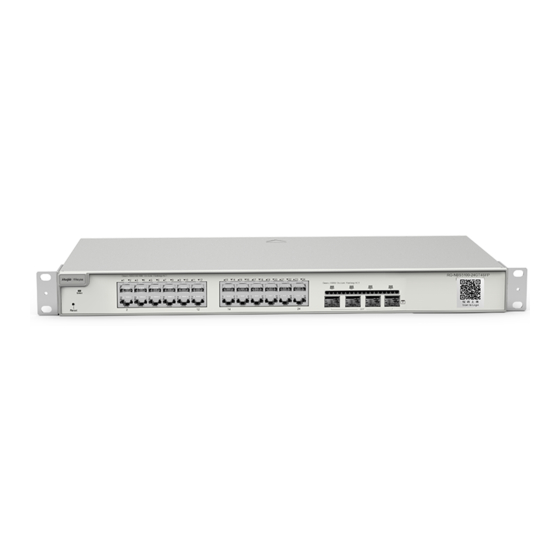
- Page 9 Ruijie RG-NBS5200 Series Switches Hardware Installation and Reference Guide Product Overview Front Panel Figure 1-6 Front Panel of RG-NBS5200-24SFP/8GT4XS Note: 1. Reset button 4. Combo port 2. System status LED 5. 10GE SFP+ port 3. 1000Base-X SFP port The switch reboots after the reset button is pressed for less than 2 seconds.
- Page 10 Ruijie RG-NBS5200 Series Switches Hardware Installation and Reference Guide Product Overview RG-NBS5200-24SFP/8GT4XS adopts fan for heat dissipation, thereby ensuring normal function of the device in the specified environment. 10 cm distance space should be reserved at both sides and the back plane of the cabinet to allow air circulation.
- Page 11 Flash Memory 256 MB SDRAM DDRIII 1GB See Appendix B. The copper cable is not supported. Optical Module The supported module type may change at any time. Consult Ruijie Networks for the latest information. 10GBase-R SFP+ Port 1000Base-X AC input...
- Page 12 Ruijie RG-NBS5200 Series Switches Hardware Installation and Reference Guide Product Overview On the front panel, the RG-NBS5200-48GT4XS Ethernet switch provides 48 10/100/1000Base-T Ethernet ports and 4 SFP+ ports. On the back panel, it provides an AC power port. Figure 1-9 Appearance of RG-NBS5200-48GT4XS...
- Page 13 Ruijie RG-NBS5200 Series Switches Hardware Installation and Reference Guide Product Overview Note: 1. Power cord retention clips 3. Protective earthing terminal 2. Three-hole AC power receptacle This device relies on the separate protective earthing terminal. The device installation shall be permanently connected to building earth by a skilled person.
-
Page 14: Preparation Before Installation
Ruijie RG-NBS5200 Series Switches Hardware Installation and Reference Guide Preparation before Installation 2 Preparation before Installation 2.1 Safety Suggestions To avoid personal injury and equipment damage, please carefully read the safety suggestions before you install the RG-NBS5200 series. The following safety suggestions may not cover all possible dangers. - Page 15 Proper humidity conditions 2.1.5 Laser The RG-NBS5200 series switches support varying models of optical modules sold on the market which are Class I laser products. Improper use of optical modules may cause damage. Therefore, pay attention to the following when you use them: ...
-
Page 16: Installation Site Requirements
2.2.1 Ventilation For the RG-NBS5200 series, a sufficient space (at least 10 cm distances from both sides and the back plane of the cabinet) should be reserved at the ventilation openings to ensure the normal ventilation. After various cables have been connected, they should be arranged into bundles or placed on the cabling rack to avoid blocking the air inlets. - Page 17 2.2.5 Grounding A good grounding system is the basis for the stable and reliable operation of the RG-NBS5200 series switches. It is the chief condition to prevent lightning stroke and resist interference. Please carefully check the grounding conditions on...
- Page 18 The grounding required for EMC design includes shielding ground, filter ground, noise and interference suppression, and level reference. All the above constitute the comprehensive grounding requirements. The resistance of earth wires should be less than 1 ohm. The RG-NBS5200 series switch back plane is reserved with one grounding pole, as shown in Figure 2-1.
-
Page 19: Lightning Resistance
2.2.6 Lightning Resistance When the AC power cable is imported outdoors and directly connected to the power port of the RG-NBS5200 series switch, lightning line bank should be adopted to prevent the switch from being hit by lightning shocks. Usage of the lightning line bank: Connect the mains supply AC cable to the lightning line bank. - Page 20 Ruijie RG-NBS5200 Series Switches Hardware Installation and Reference Guide Preparation before Installation...
-
Page 21: Product Installation
Ruijie RG-NBS5200 Series Switches Hardware Installation and Reference Guide Product Installation 3 Product Installation Please ensure that you have carefully read Chapter 2. Make sure that the requirements set forth in Chapter 2 have been met. 3.1 Installation Flowchart 3.2 Confirmations before Installation Before installation, please confirm the following points: ... - Page 22 3.3.1 Mounting the Switch to a Standard 19-inch Rack The RG-NBS5200 series switches follow the EIA standard dimensions and can be installed in 19-inch rack. Step 1: Attach the mounting brackets to the switch with the supplied screws, as shown in Figure 3-1.
-
Page 23: Mounting The Switch On A Table
Ruijie RG-NBS5200 Series Switches Hardware Installation and Reference Guide Product Installation Figure 3-3 Attaching the Brackets to the Rack 3.3.2 Mounting the Switch on a Table Attach the four rubber pads to the recessed areas on the bottom of the switch, as shown in Figure 3-4 and Figure 3-5. -
Page 24: Grounding The Switch
Ruijie RG-NBS5200 Series Switches Hardware Installation and Reference Guide Product Installation Place the switch on the table, as shown in Figure 3-5. Figure 3-5 Mounting the Switch on the Table The device must be installed and operated in the place that can restrict its movement. -
Page 25: Connecting The External Cables
Ruijie RG-NBS5200 Series Switches Hardware Installation and Reference Guide Product Installation To guarantee the security of the body and the device, the switch must be well-grounded. The grounding resistance for combined grounding should be less than 1Ω. The maintenance personnel shall check whether or not the AC socket powering the switch is well connected to the building protective earth (PE). -
Page 26: Checking After Installation
Ruijie RG-NBS5200 Series Switches Hardware Installation and Reference Guide Product Installation 3.7 Checking after Installation Before checking the installation, switch off the power supply to avoid any personal injury or damage to the component due to connection errors. Check that the ground line is connected. -
Page 27: System Commissioning
Ruijie RG-NBS5200 Series Switches Hardware Installation and Reference Guide System Commissioning 4 System Commissioning 4.1 Establishing the Configuration Environment Establishing the Configuration Environment Use the network cable to connect the PC to the switch. Figure 4-1 Configuration Environment Connecting the Console Cable ... - Page 28 Ruijie RG-NBS5200 Series Switches Hardware Installation and Reference Guide System Commissioning The console cable is correctly connected; the PC is already started; the parameters are already configured. Checking after Power-on (Recommended) After power-on, you are recommended to perform the following checks to ensure the normal operation of follow-up configurations.
-
Page 29: General Troubleshooting Flowchart
Ruijie RG-NBS5200 Series Switches Hardware Installation and Reference Guide Troubleshooting Troubleshooting 5.1 General Troubleshooting Flowchart 5.2 Troubleshooting Common Faults Symptom Possible Causes Solution Forgetting A password is manually configured but Press the reset button to restore the default management interface it is forgotten. - Page 30 Ruijie RG-NBS5200 Series Switches Hardware Installation and Reference Guide Troubleshooting that rated of the optical module. appropriate length.
-
Page 31: Appendix A Connectors And Connection Media
Ruijie RG-NBS5200 Series Switches Hardware Installation and Reference Guide Appendix A Connectors and Connection Media Appendix A Connectors and Connection Media 1000BASE-T/100BASE-TX/10BASE-T Ports The 1000BASE-T/100BASE-TX/10BASE-T is a port that supports adaptation of three rates, and automatic MDI/MDIX Crossover at these three rates. - Page 32 Ruijie RG-NBS5200 Series Switches Hardware Installation and Reference Guide Appendix A Connectors and Connection Media Optical Fiber Connection For the optical fiber ports, select single-mode or multiple-mode optical fibers for connection according to the fiber module connected. The connection schematic diagram is shown in Figure A-4:...
-
Page 33: Appendix B Mini-Gbic And Spf+ Module
Ruijie RG-NBS5200 Series Switches Hardware Installation and Reference Guide Appendix B Mini-GBIC and SPF+ Module Appendix B Mini-GBIC and SPF+ Module SFP module (Mini-GBIC module) and 10G SFP+ module are available to address the requirements of interface types of switch modules. You can select the Mini-GBIC or SFP+ module to suit your specific needs. Besides the following modules, the 10G SFP+ module also supports the Mini-GBIC-GT module. - Page 34 Ruijie RG-NBS5200 Series Switches Hardware Installation and Reference Guide Appendix B Mini-GBIC and SPF+ Module M1550 GE-SFP-SX -9.5 GE-SFP-LX 1310 -9.5 SFP-MM850 -9.5 SFP-SM1310 1310 -9.5 Table B-2 Models and Technical Specifications of the Mini-GBIC-GT Module Standard 1000Base-T SFP Type...
- Page 35 Ruijie RG-NBS5200 Series Switches Hardware Installation and Reference Guide Appendix B Mini-GBIC and SPF+ Module Table B-4 Specifications of SFP BIDI Optical Module Pairs Rate/Distance Module Pairs GE-SFP-SX-SM1310-BIDI 1000M/500m GE-SFP-SX-SM1550-BIDI GE-SFP-LX20-SM1310-BIDI 1000M/20km GE-SFP-LX20-SM1550-BIDI GE-SFP-LH40-SM1310-BIDI 1000M /40km GE-SFP-LH40-SM1550-BIDI XG-SFP-SR-SM1270-BIDI 10G /300m...
- Page 36 SFP+ 10.3125 For supported SFP+ models may change at any time, contact Ruijie Networks after-sales personnel for the latest information. If the DDM function of the AOC cable does not report transmit power, the TX power is allowed to be displayed as N/A.
-
Page 37: Appendix C Lightning Protection
Ruijie RG-NBS5200 Series Switches Hardware Installation and Reference Guide Appendix C Lightning Protection Appendix C Lightning Protection Installing AC Power Arrester (lightning protection cable row) The external lightning protection cable row shall be used on the AC power port to prevent the switch from being struck by lightning when the AC power cable is introduced from the outdoor and directly connected to the power port of the switch. - Page 38 Ruijie RG-NBS5200 Series Switches Hardware Installation and Reference Guide Appendix C Lightning Protection During the switch usage, the Ethernet port arrester shall be connected to the switch to prevent the switch damage by lightning before the outdoor network cable connects to the switch.
- Page 39 Ruijie RG-NBS5200 Series Switches Hardware Installation and Reference Guide Appendix C Lightning Protection Reversed direction of the arrester installation. You shall connect the external network cable to the “IN” end and connect the switch Ethernet port to the “OUT” end.
-
Page 40: Appendix D Cabling Recommendations
Appendix D Cabling Recommendations When RG-NBS5200 series switches are installed in standard 19-inch racks, route cable bundles upward or downward along the sides of the rack depends on the actual situation in the equipment room. All cable connectors should be placed at the bottom of the rack rather than be exposed outside of the cabinet. - Page 41 Ruijie RG-NBS5200 Series Switches Hardware Installation and Reference Guide Appendix D Cabling Recommendations Route and bundle power, signal, ground cables separately. When the cables are close to each other, cross them. When power cables run parallel to signal cables, the distance between them must b ...
- Page 42 Ruijie RG-NBS5200 Series Switches Hardware Installation and Reference Guide Appendix D Cabling Recommendations Leave a certain length of the cable connecting moving parts, such as the ground wire of the cabinet door, to avoid stress on the cable; when moving parts are in place, ensure the excess cable length shall not contact heat sources, sharp corners or edges.
-
Page 43: Appendix E Site Selection
Ruijie RG-NBS5200 Series Switches Hardware Installation and Reference Guide Appendix E Site Selection Appendix E Site Selection The machine room should be at least 5km away from the heavy pollution source such as the smelter, coal mine and thermal power plant, 3.7km away from the medium pollution source such as the chemical industry, rubber industry and electroplating industry, and 2km away from the light pollution source such as the food manufacturer and leather plant.
Need help?
Do you have a question about the RG-NBS5200 Series and is the answer not in the manual?
Questions and answers