
Related Manuals for Ruijie Reyee RG-NBS7003


Summary of Contents for Ruijie Reyee RG-NBS7003
- Page 1 Ruijie Reyee RG-NBS7003 Switch Hardware Installation and Reference Guide Document Version: V1.0 Date: April 20, 2023 Copyright © 2023 Ruijie Networks...
- Page 2 Unless otherwise agreed in the contract, Ruijie Networks does not make any express or impli ed statement or guarantee for the content of this document.
- Page 3 Intended Audience This document is intended for: Network engineers Technical support and service engineers Network administrators Technical Support Official website of Ruijie Reyee: https://www.ruijienetworks.com/products/reyee Technical support website: https://ruijienetworks.com/support Case portal: https://caseportal.ruijienetworks.com Community: https://community.ruijienetworks.com ...
- Page 4 Note An alert that contains additional or supplementary information that if not understood or followed will not lead to serious consequences. Specification An alert that contains a description of product or version support. 3. Note This manual provides the device installation steps, hardware troubleshooting, module technical specifications, and specifications and usage guidelines for cables and connectors.
-
Page 5: Product Overview
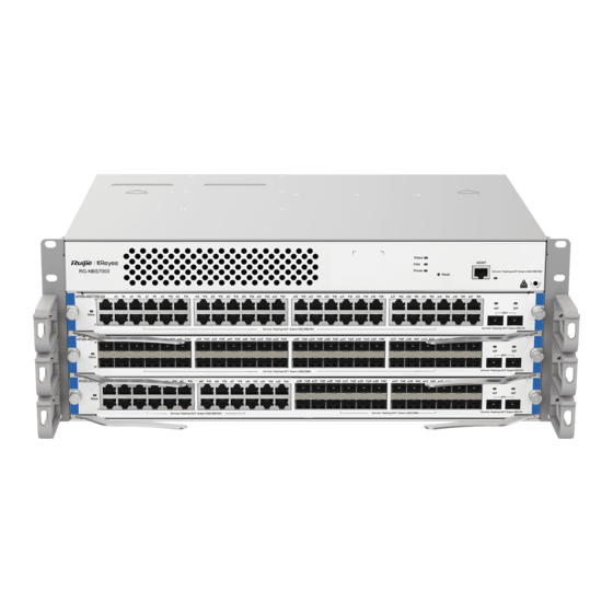
Hardware Installation and Reference Guide Product Overview Product Overview The RG-NBS7000 series switches are next-generation switches launched by Ruijie independently. The switch comes into two models : RG-NBS7003 and RG-NBS7006. RG-NBS7003: An y line card can work as a supervisor engine in slot 1 (slot 1 must be occupied). The switch provides three line card slots. - Page 6 Hardware Installation and Reference Guide Product Overview You are advised to configure power supply redundancy. System modules: The switch provides three line card slots. An y line card can work as a supervisor engine in slot 1. You can select different line cards as needed. Slot 1 must be occupied. ...
-
Page 7: Power Supply
Hardware Installation and Reference Guide Product Overview ● Press the Reset button for no more than two seconds , and all modules will be reset. ● Press the Reset button for two to five seconds, and no configurations will be changed and no module will be reset. - Page 8 The switch is powered off. Blinking green The switch is being initialized. (Fast) Blinking green The switch has been initialized and has not (Slow) accessed Ruijie Cloud. The switch has been initialized and Solid green accessed Ruijie Cloud. Possible cases: System Status LED Status 1.
-
Page 9: Heat Dissipation
Hardware Installation and Reference Guide Product Overview 1.1.7 Heat Dissipation The working temperature of the RG-NBS7003 switch ranges from 0 to 50° C (32° F to 122° F). The heat dissipation design needs to ensure the stability, safety and maintainability of the switch in such environment. The RG-NBS7003 switch adopts fan ventilation and forced convection to ensure the switch can work normally in specified environment. - Page 10 Hardware Installation and Reference Guide Product Overview 1. Air exhaust for line cards and the supervisor 2. Air exhaust for power supply modules engine (line card in slot 1 working as the supervisor engine) The line cards and the supervisor engine adopts right-to-rear airflow for proper ventilation. The power supply module adopts front-to-rear airflow for proper ventilation.
-
Page 11: Technical Specifications
Hardware Installation and Reference Guide Product Overview 1.1.8 Technical Specifications Model RG-NBS7003 Module Slot Three line card slots Supervisor Engine An y line card can work as a supervisor engine in slot 1 (slot 1 must be occupied). Supervisor Engine Not supported Redundancy The following seven line card models are available:... -
Page 12: Line Cards
Hardware Installation and Reference Guide Modules MTBF Over 200,000 hours dB at 35°C (95° F) Noise 60 dB at 50°C (122° F) Weight Net weight: 9.6 kg (21.16 lbs) Dimensions 442 mm x 313 mm x 175 mm (17.40 in. x 12.32 in. x 6.89 in., without cable management brackets), 4 RU (W x D x H) Note... - Page 13 Ports 16 x SFP+ ports For details, s ee Appendix B. (Copper cables are not supported.) SFP Modules The supported models may be subject to change without prior notice. Contact Ruijie and Cables Networks for details. Status LED Link/ACT LED...
- Page 14 Hardware Installation and Reference Guide Modules Temperature Storage –40° C to +70° C (–40° F to +158° F) Temperature Operating 10% to 90% RH (non-condensing) Humidity MTBF Over 200,000 hours Weight Net weight: 1.75 kg (3.86 lbs) Dimensions 438.5 mm x 196 mm x 40.2 mm (17.26 in. x 7.72 in. x 1.58 in.) (W x D x H) 2.1.2 M7000-24GT24SFP2XS-EA...
- Page 15 Ports 2 x SFP+ ports For details, s ee Appendix B. (Copper cables are not supported.) SFP Modules The supported models may be subject to change without prior notice. Contact Ruijie and Cables Networks for details. Status LED Link/ACT LED...
- Page 16 Hardware Installation and Reference Guide Modules Certificate Operating 0° C to 50° C (32° F to 122° F) Temperature Storage –40° C to +70° C (–40° F to +158° F) Temperature Operating 10% to 90% RH (non-condensing) Humidity MTBF Over 200,000 hours Net weight: 2.1 kg (4.63 lbs) Weight Dimensions...
- Page 17 Ports 2 x SFP+ ports For details, s ee Appendix B. (Copper cables are not supported.) SFP Modules The supported models may be subject to change without prior notice. Contact Ruijie and Cables Networks for details. Status LED Link/ACT LED...
- Page 18 Hardware Installation and Reference Guide Modules Temperature Operating 10% to 90% RH (non-condensing) Humidity MTBF Over 200,000 hours Net weight: 2.05 kg (4.52 lbs) Weight Dimensions 438.5 mm x 196 mm x 40.2 mm (17.26 in. x 7.72 in. x 1.58 in.) (W x D x H) 2.1.4 M7000-24GT2XS-EA...
- Page 19 Ports 2 x SFP+ ports For details, s ee Appendix B. (Copper cables are not supported.) SFP Modules The supported models may be subject to change without prior notice. Contact Ruijie and Cables Networks for details. Status LED Link/ACT LED...
- Page 20 Hardware Installation and Reference Guide Modules Net weight: 2.00 kg (4.41 lbs) Weight Dimensions 438.5 mm x 196 mm x 40.2 mm (17.26 in. x 7.72 in. x 1.58 in.) (W x D x H) 2.1.5 M7000-48SFP2XS-EA Module Appearance Figure 2-5 Appearance of the M7000-48SFP2XS-EA Module Ports The M7000-48SFP2XS-EA module provides 48 x SFP ports and 2 x SFP+ ports.
- Page 21 Ports 2 x SFP+ ports For details, s ee Appendix B. (Copper cables are not supported.) SFP Modules The supported models may be subject to change without prior notice. Contact Ruijie and Cables Networks for details. Status LED Link/ACT LED...
- Page 22 Hardware Installation and Reference Guide Modules Figure 2-6 Appearance of the M7000-24SFP2XS-EA Module Ports The M7000-24SFP2XS-EA module provides 24 x SFP ports and 2 x SFP+ ports. The SFP port supports the 100/1000 Mbps auto-negotiation and hot swapping. The SFP+ port supports 10GE SFP+ modules, 1GE SFP modules, and hot swapping.
- Page 23 Ports 2 x SFP+ ports For details, s ee Appendix B. (Copper cables are not supported.) SFP Modules The supported models may be subject to change without prior notice. Contact Ruijie and Cables Networks for details. Status LED Link/ACT LED...
- Page 24 Ports 8 x SFP+ ports For details, s ee Appendix B. (Copper cables are not supported.) SFP Modules The supported models may be subject to change without prior notice. Contact Ruijie and Cables Networks for details. Status LED Link/ACT LED...
-
Page 25: Power Supply Modules
Hardware Installation and Reference Guide Modules Consumption Certificate Operating 0° C to 50° C (32° F to 122° F) Temperature Storage –40° C to +70° C (–40° F to +158° F) Temperature Operating 10% to 90% RH (non-condensing) Humidity MTBF Over 200,000 hours Net weight: 1.75 kg (3.86 lbs) Weight... - Page 26 Hardware Installation and Reference Guide Modules Indicator Status Meaning A power fault occurs or there is no power input. Status LED Solid green The module is operating normally. Specifications Module Model RG-PA300I-FS Rated Voltage 100 V AC to 120 V AC, 200 V AC to 240 V AC; 50 Hz to 60 Hz Range Max Voltage 90 V AC to 264 V AC;...
- Page 27 Hardware Installation and Reference Guide Modules Figure 2-9 Appearance of the RG-PA460I-FS Module Ports RG-PA460I-FS module provides 12 V AC input to the RG-NBS7003 switch. The front panel of the power supply module provides a 3-pin connector, which can be connected to a standard 10 A power cord. Indicator Status Meaning...
-
Page 28: Fan Modules
Hardware Installation and Reference Guide Modules Caution ● When you plug in a power cord, press the retention clip toward the plug to secure the cord. ● Connect a power cord to an output socket connected to the ground. ● The max operation altitude and storage altitude are both 5000 m (16404.2 ft). Fan Modules 2.3.1 M7003-FAN... - Page 29 Hardware Installation and Reference Guide Modules Rotation speed monitoring and failure alarm Status Monitoring Automatic Speed Automatic speed adjustment based on temperature Adjustment The fan tray supports hot swapping. For operation details, see Hardware Hot Swapping Maintenance.
-
Page 30: Preparation Before Installation
Hardware Installation and Reference Guide Preparation before Installation Preparation before Installation Safety Suggestions Caution ● To avoid body injury and equipment damage, carefully read the safety suggestions before you install the RG-NBS7000 series switches. ● The following safety suggestions do not cover all possible dangers. 3.1.1 General Safety Precautions ... -
Page 31: Static Discharge Damage Prevention
Hardware Installation and Reference Guide Preparation before Installation Find out the location of the emergency power supply switch in the room be fore installation. First cut off the power supply in case of an accident. Be sure to make a careful check before you shut down the power supply. ... -
Page 32: Laser Safety
Hardware Installation and Reference Guide Preparation before Installation Caution ● For safety, use a multimeter to measure the resistance between yourself and the ground, which should range from 1 Ω to 10 Ω. ● Make sure that the switch is properly grounded when the anti -static wrist strap is connected to the ground by the jack on the chassis. -
Page 33: Space Requirements
Hardware Installation and Reference Guide Preparation before Installation 3.2.2 Space Requirements The width of the machine room corridor should be greater than 0.8 m (31.50 in.) to ensure enough space to move the chassis, and to plug and remove modules. ... -
Page 34: Humidity Requirements
Hardware Installation and Reference Guide Preparation before Installation 3.2.5 Humidity Requirements To ensure the normal operation and a prolonged use life of the switch, you must maintain an appropriate humidity in the equipment room. Otherwise, the equipment may be damaged. ... -
Page 35: Power Requirements
Hardware Installation and Reference Guide Preparation before Installation Note The Average refers to the average value of harmful gas measured in one week. The Maximum value is the upper limit of the harmful gas in one week, and maximum value can last for up to 30 minutes every day. 3.2.7 Power Requirements The following power supply modules are available:... - Page 36 Hardware Installation and Reference Guide Preparation before Installation Caution ● The RG-NBS7003 switch provides 1+1 power redundancy. You are advised to use multiple power supplies for the equipment to ensure its continuous and stable operation by avoiding the impact of unexpected power failures on the equipment.
-
Page 37: Cabinet Mounting
Hardware Installation and Reference Guide Preparation before Installation yellow/green safety cable ground. The lightning discharge ground is for the facility only, irre levant to the equipment. Note For switch lightning protection, see Appendix C. EMC Grounding The ground required for EMC design includes shielding ground, filter ground, noise and interference suppression, and level reference. - Page 38 Hardware Installation and Reference Guide Preparation before Installation Figure 3-2 19-inch Cabinet Be sure that the square hold strip is at least 125 mm (4.92 in.) far from the outboard front door and the door is at most 25 mm (0.98 in.) thick to ensure a minimum available distance of 100 mm (3.94 in.). The front door is at least 500 mm (19.69 in.) far from the back door.
-
Page 39: Installation Tools
Hardware Installation and Reference Guide Preparation before Installation Be sure that the front and back doors of the cabinet have porosities greater than 50% for good ventilation and heat dissipation. Installation Tools Phillips screwdriver, related Ethernet and fiber-optic cables, cage nuts, Common Tools diagonal plier, and cable ties Anti-static wrist strap, wire stripper, crimping plier, and wire cutter... -
Page 40: Installing The Switch
Hardware Installation and Reference Guide Installing the Switch Installing the Switch The RG-NBS7000 series switches must be used and fixed indoors. Note Ensure that you have carefully read Chapter 2 and make sure that the requirements in Chapter 2 are all met. Installation Procedure Before You Begin Carefully plan and arrange the installation location, networking method, power supply, and wiring before... -
Page 41: Mounting The Cabinet
Hardware Installation and Reference Guide Installing the Switch Mounting Cable Management Frames Note ● Wear an anti-static wrist strap and ensure that the anti-static wrist strap is grounded well. ● The cable management brackets are not mounted before delivery. See the following steps and figures for installation. - Page 42 Hardware Installation and Reference Guide Installing the Switch The front/rear doors of the cabinet should be installed to allow you open and close them smoothly. The locks should work normally, and all keys should be complete. There should be no unnecessary and informal labels inside the cabinet and on line cards. ...
-
Page 43: Mounting The Switch To A Cabinet
Hardware Installation and Reference Guide Installing the Switch represents entire-U delimiters Caution ● Before installing a slide rail, make sure that the bearing capacity of the slide rail meets requirements. ● There are various slide rails. The rail appearance and installation method is subject to actual conditions. ●... - Page 44 Hardware Installation and Reference Guide Installing the Switch Figure 4-3 Slide Rail Installation Positions (2) Place the switch on the slide rail, and drive it smoothly into the cabinet until the bracket reaches the square hole strip. (3) Align the installation holes on the bracket with the cage nuts on the square hole strip, and drive screws into the holes.
-
Page 45: Grounding The Switch
Hardware Installation and Reference Guide Installing the Switch Grounding the Switch Note A good grounding system protects your switch against lightning strikes and interferences and ensures its normal operation and reliability. Precaution The sectional area of the grounding wire should be determined according to the possible maximum current. Cables with good conductor should be used. -
Page 46: Installing A Power Supply Module
Hardware Installation and Reference Guide Installing the Switch ● The power socket should be installed near the device and easily accessible. ● When installing the switch, connect the grounding first and disconnect it last. ● The cross-sectional area of the protection ground wire should be at least 2.5 mm (12 AWG). -
Page 47: Installing A Fan Module
Hardware Installation and Reference Guide Installing the Switch Caution ● The total power of installed power supply modules must be greater than the working power of the switch. Otherwise, some modules may fail to work. ● The switch power is the sum of the power of all working modules, including the supervisor engine, line cards and fan modules. - Page 48 Hardware Installation and Reference Guide Installing the Switch system. You can select Reset Backup to restore previous configurations, or select Delete Backup to delete previous configurations. See Figure 1-2 for the Reset button. ● Remove the filler panel in a slot before installing a line card. Figure 4-8 RG-NBS7003 Supervisor Engine Slots and Line Card Slots 2.
- Page 49 Hardware Installation and Reference Guide Installing the Switch 4.10 Installing an SFP or SFP+ Module (Optional) Caution Make sure the optical modules connected to both ends of a fiber-optic cable are of the same model. Preparation (1) To avoid damages to SFP or SFP+ modules and electronic components in the device caused by the static electricity generated during the installation, wear an anti-static wrist strap close to your skin and have it properly grounded.
-
Page 50: Connecting The Power Cord
Hardware Installation and Reference Guide Installing the Switch Precautions The optical module cannot be inserted inversely. If the optical module cannot be inserted to the end, do not push it with force. Please try the other end of the module. ... -
Page 51: Installation Verification
Hardware Installation and Reference Guide Installing the Switch 4.12 Installation Verification Note Make sure all power supplies are cut off before checking the installation to avoid personal injury and device damage. Before powering up the switch, please verify the following requirements: ... -
Page 52: Establishing The Configuration Environment
Hardware Installation and Reference Guide Verifying Operating Status Verifying Operating Status Establishing the Configuration Environment Configuring Terminal Parameters Figure 5-1 Configuration Environment of the RG-NBS7003 Connecting the Cable Connect the end of the cable with a crystal connector to the network port of the PC. ... - Page 53 Hardware Installation and Reference Guide Verifying Operating Status Checking after Power-on (Recommended) After power-on, you are advised to perform the following checks to ensure the normal operation of follow -up configurations. Check that the device indicator is normal.
-
Page 54: Monitoring And Maintenance
Hardware Installation and Reference Guide Monitoring and Maintenance Monitoring and Maintenance Monitoring When the switch is running, you can monitor the status of each module by observing the status LEDs. When the status LED of the chassis is red, it means a module is faulty. Log in to the Web management system to perform troubleshooting. - Page 55 Hardware Installation and Reference Guide Monitoring and Maintenance Please contact the technical support representatives of Ruijie Networks for replacing fuses. Technical staff of Ruijie Networks will replace the fuse of the same model. The following table lists the specifications of the fuse for each module.
-
Page 56: Common Troubleshooting
Hardware Installation and Reference Guide Troubleshooting Troubleshooting Troubleshooting Flowchat Common Troubleshooting Fault 1: The power supply module does not work. Symptom The Status LED of each line card is off, the Status LED of the fan is off, and the fan does not work. The LED on the panel of the power module is off. - Page 57 Hardware Installation and Reference Guide Troubleshooting The Status LED of the line card is off or continuously blinking. The Link/ACT LED of the line card is solid on when no network cable or fiber-optic cable is connected. Suggested Action (1) Check if the line card is firmly inserted. If not, install the line card again and ensure that it is inserted into place before you tighten the captive screws on the two sides of the panel.
- Page 58 (4) Check whether the rates of the two sides match and whether the fiber-optic cable type meets requirements. In addition, for ports supporting different rates, check whether rate modes are configured correctly. Note If preceding methods do not take effect, please contact Ruijie Networks for technical support.
-
Page 59: Replacing Modules
Hardware Installation and Reference Guide Replacing Modules Replacing Modules Removing an SFP or SFP+ Module (1) Unplug the fiber-optic cable. (2) Turn down the handle of the module until it is horizontal. Pull the tab to take out the SFP or SFP+ module, as shown in Figure 8-1. -
Page 60: Replacing A Power Supply Module
Hardware Installation and Reference Guide Replacing Modules (6) As shown in step 5 in Figure 8-2, place one hand under the module to support its weight and hold the module with your other hand. Push the module into the slot along the guide rail. (7) As shown in step 6 in Figure 8-2, rotate the ejector levers toward the front of the module. -
Page 61: Replacing A Fan Module
Hardware Installation and Reference Guide Replacing Modules (1) Unplug the cable. Separate the pigtail plug of the cable from the connector of the power supply module. (2) Grasp the handle of the module and pull firmly to slide the power supply halfway out of the chassis. (3) Hold the front of the module with one hand and hold the bottom of the module with the other hand to pull it slowly from the slot. - Page 62 Hardware Installation and Reference Guide Replacing Modules (4) Tighten captive screws to secure the fan module with a Phillips screwdriver. Figure 8-4 Replacing a Fan Module...
-
Page 63: Bundling The Cables
Hardware Installation and Reference Guide Cables Cables Note This chapter describes the precautions and simple steps for cable connection and bundling. For details, see Cabling Recommendations Connecting External Port Cables Precautions Correctly distinguish single-mode and multi-mode fiber-optic cables and ports. ... - Page 64 Hardware Installation and Reference Guide Appendix Appendix 10.1 Connectors and Media 1000BASE-T/100BASE-TX/10BASE-T Port The 1000BASE-T/100BASE-TX/10BASE-T is a 10/100/1000 Mbps port with auto-negotiation, which supports auto MDI/MDIX Crossover at these three rates . The 1000BASE-T complies with IEEE 802.3ab standard, and uses up to 100 m of 100-ohm CAT5, CAT 5e or twisted pairs with higher standard.
- Page 65 Hardware Installation and Reference Guide Appendix Figure 10-3 Connections of the Twisted Pairs of the 100BASE-TX/10BASE-T Fiber-Optic Cable Connection For the optical ports, select single-mode or multimode fiber-optic cables for connections according to the optical module connected. Figure 10-4 shows the connection schematic diagram. Figure 10-4 Fiber-Optic Cable Connections...
- Page 66 SFP modules (mini-GBIC module) and 10GE SFP+ modules are available to cope with interface types of switch modules. You can select the mini-GBIC module to suit your specific needs. The models and technical specifications of some mini-GBIC and 10GE SFP+ modules are listed below. For details, see Ruijie Module Installation and Reference Guide.
- Page 67 Hardware Installation and Reference Guide Appendix Table 10-2 Models of 1GE SFP Copper Module Standard Model DDM (Yes/No) 1000Base-T Mini-GBIC-GT Table 10-3 SFP Module Cabling Specification Fiber SFP Model Interface Type Core Size(μm) Cabling Type Distance 62.5/125 275 m MINI-GBIC-SX-MM850 50/125 550 m MINI-GBIC-LX-SM1310...
- Page 68 Hardware Installation and Reference Guide Appendix Category 5 (or above ) UTP or GE-SFP-GT RJ45 100 m Category 5 (or above ) UTP or SFP-GT RJ45 100 m Note ● For the optical module with the transmission distance exceeding 4 0 km (24.85 miles) or above, add one in-line optical attenuator on the link to avoid the overload of the optical receiver when short single -mode fiber-optic cables are used.
- Page 69 Hardware Installation and Reference Guide Appendix SFP+MM850 -7.3 -9.9 XG-SFP-LR-SM1270- 1270 -6.5 -14.4 BIDI XG-SFP-LR-SM1330- 1330 -6.5 -14.4 BIDI XG-LR-SM1310 1310 -8.2 -14.4 SFP+SM1310 1310 -8.2 -14.4 XG-SFP-LR-SM1310 1310 -8.2 -14.4 XG-eSFP-LR-SM131 1310 -8.2 -14.4 XG-SFP-ER-SM1550 1550 -4.7 -11.3 XG-SFP-ZR-SM1550 1550 SFP-S4-R1000P1 v2 1310...
- Page 70 Note The types/models of the SFP+ modules are being updated. If more accurate models of the module are required, contact Ruijie marketing staff or technical support engineers. The TX power of AOC cable can be displayed as “N/A”. Table 10-7...
-
Page 71: Lightning Protection
Hardware Installation and Reference Guide Appendix 10.3 Lightning Protection Installing AC Power Arrester (lightning protection cable row) The external lightning protection cable row must be used on the AC power port to prevent the switch from being struck by lightning when the AC power cable is introduced from the outdoor and directly connected to the power port of the switch. - Page 72 Hardware Installation and Reference Guide Appendix During the switch usage, the Ethernet port arrester must be connected to the s witch to prevent the switch damage by lightning before the outdoor network cable connects to the switch. Tools: cross or straight screwdriver, multimeter, and diagonal pliers Installation steps: (1) Tear one side of the protection paper for the double -sided adhesive tape and paste the tape to the framework of the Ethernet port arrester.
- Page 73 Hardware Installation and Reference Guide Appendix To prevent the performance of the Ethernet port arrester from being affected, note the following points: Reversed direction of the arrester installation: Connect the external network cable to the IN end and connect the switch Ethernet port to the OUT end.
-
Page 74: Cabling Recommendations
Hardware Installation and Reference Guide Appendix 10.4 Cabling Recommendations When RG-NBS7000 series switches are installed in standard 19-inch cabinets, cables are tied in the binding rack on the cabinet by the cabling rack, and top or bottom cabling is adopted according to the actual situation in the equipment room. - Page 75 Hardware Installation and Reference Guide Appendix Figure 10-7 Bundling Cables (1) Cables of different types (such as power cords, signal cables, and ground cables) should be separated in cabling and bundling. When they are close, crossover cabling can be adopted. In the cas e of parallel cabling, maintain a space of at least 30 mm (1.18 in.) for power cords and signal cables.
- Page 76 Hardware Installation and Reference Guide Appendix Figure 10-9 Bundling Cables (3) Cables not to be assembled or remaining parts of cables should be folded and placed in a proper position of the cabinet or cabling slot. The proper position will not affect device running or cause device or cable damage during commissioning.
- Page 77 Hardware Installation and Reference Guide Appendix Do not use self-tapping screws to fasten terminals. Power cables of the same type in the same cabling direction should be bundled up into cable bunches, with clean and straight cables in cable bunches. ...
-
Page 78: Site Selection
Hardware Installation and Reference Guide Appendix 10.5 Site Selection The equipment room should be at least 5 km (3.11 miles) away from the heavy pollution source such as the smelter, coal mine, and thermal power plant, 3.7 km (2.30 miles) away from the medium pollution source such as the chemical industry, rubber industry, and electroplating industry, and 2 km (1.24 miles) away from the light pollution source such as the food m anufacturer and leather plant.
Need help?
Do you have a question about the Reyee RG-NBS7003 and is the answer not in the manual?
Questions and answers