
Related Manuals for Ruijie Reyee RG-NBS5200-24GT4XS-P


Summary of Contents for Ruijie Reyee RG-NBS5200-24GT4XS-P
- Page 1 Ruijie Reyee RG-NBS5200-24GT4XS-P Switch Hardware Installation and Reference Guide Document Version: V1.1 Date: January 17, 2023 Copyright © 2023 Ruijie Networks...
- Page 2 Due to product version upgrades or other reasons, the content of this document will be updated from time to time. Ruijie Networks reserves the right to modify the content of the document without any notice or prompt. This manual is for reference only. Ruijie Networks endeavors to ensure content accuracy and will not shoulder...
-
Page 3: Preface
Intended Audience This document is intended for: Network engineers Technical support and servicing engineers Network administrators Technical Support The official website of Ruijie Reyee: https://www.ruijienetworks.com/products/reyee Technical Support Website: https://www.ruijienetworks.com/support Case Portal: https://caseportal.ruijienetworks.com Community: https://community.ruijienetworks.com... - Page 4 Note This manual provides the device installation steps, hardware troubleshooting, module technical specifications, and specifications and usage guidelines for cables and connectors. It is intended for the users who have some experience in installing and maintaining network hardware. At the same time, it is assumed that the users are already familiar with the related terms and concepts.
-
Page 5: Table Of Contents
Contents Preface ..............................I 1 Product Overview ..........................1 1.1 RG-NBS5200-24GT4XS-P ......................1 1.2 Package Contents........................1 1.3 Appearance ..........................2 1.3.1 Front Panel ........................2 1.3.2 Rear Panel ........................3 1.3.3 Ventilation ........................4 1.4 Technical Specifications ......................4 2 Preparing for Installation ........................ - Page 6 2.2.7 Lightning Protection Requirements ................12 2.2.8 EMI Requirements ....................... 12 2.2.9 Installation Site Requirements ..................13 2.3 Rack Requirements ......................... 13 2.4 Tools ............................14 3 Installing the Switch ........................15 3.1 Installation Flowchart ....................... 15 3.2 Before You Begin ........................16 3.3 Installing the Switch .........................
- Page 7 6.1 Connectors and Media ......................25 6.2 Mini-GBIC Modules and SFP+ Modules .................. 27 6.3 Lightning Protection ......................... 32 6.4 Cabling Recommendations...................... 35 6.4.1 Requirement for the Minimum Bend Radius of an Ethernet Cable ......35 6.4.2 Requirement for the Minimum Bend Radius of a Fiber-Optic Cable ......35 6.4.3 Precautions for Bundling up Cables ................
-
Page 8: Product Overview
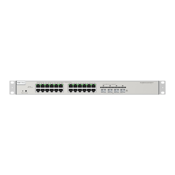
SFP+ ports on the front panel, and an AC power input plug on the rear panel. The switch supports routing, Rapid Spanning Tree Protocol (RSTP) and link aggregation. It can be managed through Eweb, Ruijie Cloud and App. Package Contents... -
Page 9: Appearance
Hardware Installation and Reference Guide Product Overview Item Quantity Management Software Grounding Cable Power Cord (1.8 m/5.91 ft) Power Cord Retention Clip User Manual Warranty Card Note The above is the general Packet Contents. The actual delivery is subject to the order contract. And please check your goods carefully against the order contract. -
Page 10: Rear Panel
Fast blinking (0.5 Hz): The switch is operating properly but not connected to System Status Ruijie Cloud, Fast blinking (10 Hz): The switch is upgrading or restarting. Solid green: The switch is operating properly and connected to Ruijie Cloud. Off: The LED indicates the Link/ACK status. Port Status LED Mode Solid green: The LED indicates the PoE status. -
Page 11: Ventilation
Hardware Installation and Reference Guide Product Overview Item Description Secure the grounding lug to ensure connection between the chassis and earth Grounding Screw ground. 1.3.3 Ventilation The RG-NBS5200-24GT4XS-P switch adopts the side-to-rear airflow design to ensure that the switch works properly in the specified environment. - Page 12 Hardware Installation and Reference Guide Product Overview SDRAM DDRIII 512 MB 24 10/100/1000Base-T Ethernet ports with auto negotiation and crossover detection (auto MDI/MDIX crossover) Ports 1 to 24 are PoE-capable Port Four 10GE SFP+ ports The switch itself does not transmit optical signals. You must install an optical transceiver module on the switch to convert optical signals into electrical signals.
- Page 13 Hardware Installation and Reference Guide Product Overview Lightning Protection (Port 6 kV Surge Protection) Certification Dimensions (W × D × H) 440 mm x 357.6 mm x 43.6 mm (17.32 in. x14.08 in. x 1.72 in.) Weight 5.62 kg (12.39 lbs, including the package) Warning ●...
-
Page 14: Preparing For Installation
Hardware Installation and Reference Guide Preparing for Installation Preparing for Installation Safety Precautions Note ● To avoid personal injury and device damage, carefully read the safety precautions before you install the switch. ● The following safety precautions may not cover all possible dangers. 2.1.1 General Safety Precautions ... -
Page 15: Static Electricity
Hardware Installation and Reference Guide Preparing for Installation the case of accidents. Make sure that the switch is powered off when you cut off the power supply. Equip the power supply system with a leakage protector (also referred to as “leakage current switch” or “leakage current breaker”) to automate the power cut-off in the case of power leakage or shock. -
Page 16: Installation Environment Requirements
Hardware Installation and Reference Guide Preparing for Installation When an optical transceiver is working, ensure that its port has been connected with an optical fiber or covered by a dust cap to keep out dust and prevent it from burning your eyes. ... -
Page 17: Cleanliness Requirements
Hardware Installation and Reference Guide Preparing for Installation Note The working temperature and humidity of the switch are measured at the point that is 1.5 m (59.06 in.) above the floor and 0.4 m (15.75 in.) before the device when there is no protective plate in front or at the back of the switch. -
Page 18: Grounding Requirements
Hardware Installation and Reference Guide Preparing for Installation 2.2.6 Grounding Requirements A proper grounding system is the basis for stable and reliable running. It is indispensable for preventing lightning strikes and interference. Carefully check the grounding conditions at the installation site according to the grounding specifications, and complete grounding properly based on the actual situation. -
Page 19: Lightning Protection Requirements
Hardware Installation and Reference Guide Preparing for Installation grounding and safety grounding of the rack. Lightning grounding is required only for facilities and is not required for the switch. Note For lightning protection, please see Section 6.3 Lightning Protection. EMC Grounding Grounding required for electromagnetic compatibility includes shielded grounding, filter grounding, noise and interference suppression, and level reference. -
Page 20: Installation Site Requirements
Hardware Installation and Reference Guide Preparing for Installation 2.2.9 Installation Site Requirements Regardless of whether the device is installed in a rack or on a workbench, observe the following conditions: Maintain a proper clearance around the air intakes and outlets for heat dissipation. ... -
Page 21: Tools
Hardware Installation and Reference Guide Preparing for Installation Tools Table 2-3 Tools Common Phillips screwdriver, power cords, Ethernet cables, fastening bolts, diagonal plier and cable Tools ties Anti-static wrist strap, wire stripper, crimping plier, crystal connector crimping plier, and wire Special Tools cutter Meters... -
Page 22: Installing The Switch
Hardware Installation and Reference Guide Installing the Switch Installing the Switch Caution Before installing the switch, make sure that you have carefully read and met the requirements specified in Chapter 2. Installation Flowchart Install the switch Ground the switch Connect the power supply Connect the cables Bundle the cables Verify the installation... -
Page 23: Before You Begin
Hardware Installation and Reference Guide Installing the Switch Before You Begin The installation site provides sufficient space for heat dissipation. The installation site meets the temperature and humidity requirements of the switch. The power supply is available in the installation site and meets requirement for current. ... - Page 24 Hardware Installation and Reference Guide Installing the Switch Figure 3-1 Securing Mounting Brackets Step 2: Use M6 screws and cage nuts to secure the other end of the mounting brackets to square hole rack posts. Figure 3-2 Installing Cage Nuts and Screws...
-
Page 25: Installing The Switch On A Workbench
Hardware Installation and Reference Guide Installing the Switch Figure 3-3 Tightening Screws 3.3.2 Installing the Switch on a Workbench Step 1: Attach the four rubber feet to the four corners at the bottom of the switch. Figure 3-4 Attaching Rubber Feet to the Bottom of the Switch Step 2: Place the switch on a workbench and ensure adequate airflow around the switch. -
Page 26: Connecting The Switch To Earth Ground
Hardware Installation and Reference Guide Installing the Switch Figure 3-5 Installing the Switch on a Workbench Note The location where the switch is installed must be subject to movement restrictions. Connecting the Switch to Earth Ground The switch has a grounding stud on the rear panel. Connect the grounding stud to the grounding lug of the rack and then connect the grounding lug of the rack to the ground buss bar of the machine room. -
Page 27: Bundling Cables
Hardware Installation and Reference Guide Installing the Switch Precautions Make sure that the models of optical transceivers and optical cables match with SFP ports. The transmitting port on the local device should be connected to the receiving port on the peer device and vice versa. ... -
Page 28: Verifying Operating Status
Hardware Installation and Reference Guide Verifying Operating Status Verifying Operating Status Setting up Configuration Environment Connect the PC to the management port of the switch with an Ethernet cable. Figure 4-1 Configuring Environment Connecting an Ethernet Cable Plug the crystal head of the Ethernet cable into the network port of the PC. Connect the RJ-45 end to any port of the switch. - Page 29 Hardware Installation and Reference Guide Verifying Operating Status The main program is loaded properly. Service ports can forward data properly.
-
Page 30: Common Troubleshooting
The device is not working properly Check the device installation Check the power connection Check the LEDs on the device Check the cable connection Contact Technical Support of Ruijie Networks Common Faults Symptom Possible Cause Suggested Action Press and hold the Reset button for over five... - Page 31 Hardware Installation and Reference Guide Common Troubleshooting The port is specially configured mode as the interconnected switch. and does not use the same work mode as the interconnected switch. The receiving and transmitting ends are connected incorrectly. Exchange the transmission and receiving The types of the interconnected ends of the optical fiber.
-
Page 32: Appendix
Hardware Installation and Reference Guide Appendix Appendix Connectors and Media 1000BASE-T/100BASE-TX/10BASE-T Port 1000BASE-T/100BASE-TX/10BASE-T is a 10/100/1000 Mbps port that supports auto negotiation and auto MDI/MDIX crossover. Compliant with IEEE802.3ab, 1000BASE-T requires Category 5(5e) 100-ohm UTP or STP. SPT is recommended. - Page 33 Hardware Installation and Reference Guide Appendix The following figure shows feasible connections of straight-through and crossover twisted-pair cables for 100BASE-TX/10BASE-T. Figure 6-2 100BASE-TX/10BASE-T Twisted Pair Connections Fiber-Optic Cable Connection Choose single mode or multi-mode fibers according to the module types. Figure 6-3 Fiber-Optic Cable Connection...
-
Page 34: Mini-Gbic Modules And Sfp+ Modules
Besides, the Mini-GBIC-GT modules are also supported. The following models and technical specifications of some SFP modules and 10GE SFP+ modules are listed for your reference. For details about the technical specifications, see Ruijie Transceiver Installation and Reference Guide. Table 6-2... - Page 35 Hardware Installation and Reference Guide Appendix MINI-GBIC-ZX100- 1550 SM1550 GE-SFP-SX -9.5 GE-SFP-LX 1310 -9.5 SFP-MM850 -9.5 SFP-SM1310 1310 -9.5 Table 6-3 1000Base-T SFP Copper Module DDM Supported Standard 1000Base-TSFP Module (Yes/No) 1000Base-T Mini-GBIC-GT Table 6-4 Cabling Specifications of SFP Modules Max Cable Model Connector...
- Page 36 Hardware Installation and Reference Guide Appendix MINI-GBIC-ZX80-SM1550 9/125 80 km MINI-GBIC-ZX100-SM1550 9/125 100 km 62.5/125 275 m GE-SFP-SX 50/125 550 m GE-SFP-LX 9/125 10 km Mini-GBIC-GT RJ45 cable Cat 5 (or better) twisted-pair cable 100 m Caution ● For optical transceivers with a maximum cabling distance of over 40 km (including 40 km), install an optical attenuator to avoid overload when using short-distance SMFs.
- Page 37 Hardware Installation and Reference Guide Appendix (Yes/No XG-SFP-SR-MM850 -7.3 -9.9 XG-SFP-ZRV1 -7.3 -9.9 XG-SR-MM850 -7.3 -9.9 SFP+MM850 -7.3 -9.9 XG-SFP-SR-SM1270- 1270 BIDI XG-SFP-SR-SM1330- 1270 BIDI XG-SFP-LR-SM1270- 1270 -6.5 BIDI 14.4 XG-SFP-LR-SM1330- 1330 -6.5 BIDI 14.4 XG-LR-SM1310 1310 -8.2 14.4 XG-SFP-LR-SM1310 1310 -8.2 14.4...
- Page 38 ● The SFP+ modules may change at any time. For the latest information, contact the marketing personnel or technical support personnel of Ruijie Networks. ● If the DDM function of the AOC cable does not report transmit power, Tx power value shows as N/A.
-
Page 39: Lightning Protection
Hardware Installation and Reference Guide Appendix Lightning Protection Installing an AC Power Arrester (Lightning Resistance Socket) When an AC power cord is introduced from outdoors and directly connected to the power port of the switch, the AC power port must be connected to an external lightning protection power strip to protect the switch against lightning strokes. - Page 40 Hardware Installation and Reference Guide Appendix rectify the polarity of the connection. If the indicator is still red, the arrester's PE terminal is not grounded. Installing the Ethernet Port Arrester Connect an Ethernet port arrester to the switch to prevent the damage by lightning before connecting an outdoor network cable to the switch.
- Page 41 Hardware Installation and Reference Guide Appendix after grounding. Incomplete arrester installation. If there is more than one port connected to the peer device on the switch, arresters need to be installed on all connection ports for the purpose of lightning protection.
-
Page 42: Cabling Recommendations
Hardware Installation and Reference Guide Appendix Cabling Recommendations When the switch is installed in a standard 19-inch rack, secure the cables around the cable management brackets. Adopt top cabling or bottom cabling according to the actual situation in the machine room. All adapted connectors should be placed at the bottom of the rack in an orderly manner instead of outside the rack that is easy to touch. - Page 43 Hardware Installation and Reference Guide Appendix Figure 6-6 Binding Cables (1) Cables of different types (such as power cords, signal cables, and grounding cables) should be separated in cabling and bundling. Mixed bundling is disallowed. When they are close to each other, you are advised to adopt crossover cabling.
- Page 44 Hardware Installation and Reference Guide Appendix stress may be generated on the cables and causes the wires inside to break. Figure 6-8 Binding Cables (3) Cables not to be assembled or remaining parts of cables should be folded and placed in a proper position of the rack or cable trough.
- Page 45 Hardware Installation and Reference Guide Appendix Hard power cords should be fastened in the terminal connection area to prevent stress on terminal connection and cable. Do not use self-tapping screws to fasten terminals. Power cords of the same type and in the same cabling direction should be bundled up into cable bunches, with cables in cable bunches clean and straight.
-
Page 46: Site Selection
Hardware Installation and Reference Guide Appendix Site Selection The machine room should be at least 5 km (3.11 miles) away from heavy pollution sources, such as the smelter works, coal mine, and thermal power plant. The machine room should be at least 3.7 km (2.30 miles) away from medium pollution sources, such as the chemical factory, rubber factory, and electroplating factory.
Need help?
Do you have a question about the Reyee RG-NBS5200-24GT4XS-P and is the answer not in the manual?
Questions and answers