Ruijie Reyee RG-NBS3200 Series Hardware Installation And Reference Manual
Hide thumbs
Also See for Reyee RG-NBS3200 Series:
- Hardware installation and reference manual (52 pages)
Table of Contents
Advertisement
Quick Links
Advertisement
Table of Contents

Related Manuals for Ruijie Reyee RG-NBS3200 Series


Summary of Contents for Ruijie Reyee RG-NBS3200 Series
- Page 1 Ruijie RG-NBS3200 Series Switches RG-NBS3200-24GT4XS&RG-NBS3200-24SFP/8GT4XS& RG-NBS3200-24GT4XS-P&RG-NBS3200-48GT4XS& RG-NBS3200-48GT4XS-P Hardware Installation and Reference Guide Document Version: V1.1 Date: 2022-11-16 Copyright © 2023 Ruijie Networks...
- Page 2 Ruijie Networks reserves the right to modify the content of the document without any notice or prompt. This manual is designed merely as a user guide. Ruijie Networks has tried its best to ensure the accuracy and reliability of the content when compiling this manual, but it does not guarantee that the content of the manual is completely free of errors or omissions, and all the information in this manual does not constitute any explicit or implicit warranties.
- Page 3 It is intended for the users who have some experience in install ing and maintaining network hardware. At the same time, it is assumed that the users are already familiar with the related terms and concepts. Obtaining Technical Assistance Ruijie Networks website: https://www.ruijienetworks.com/ Technical support website: https://www.ruijienetworks.com/support...
- Page 4 Note An alert that contains additional or supplementary information that if not understood or followed will not lead to serious consequences. Specification An alert that contains a description of product or version support. 2. Note This manual provides installation steps, troubleshooting, technical specifications, and usage guidelines for cables and connectors.
-
Page 5: Product Overview
Product Overview 1 Product Overview Ruijie RG-NBS3200 series switches are mainly applicable to the small- and medium-sized enterprise (SME) networks to provide services according to service needs to ensure prompt transmission of key data. The RG-NBS3200 series switches provide various interfaces to meet different requirements . - Page 6 Ruijie RG-NBS3200 Series Switches Hardware Installation and Reference Guide Product Overview Maximum voltage range: 90 V to 264 V Frequency: 50/60 Hz Rated current: 1.5 A Input Leakage ≤ 3.5 mA Current Supported Not supported Power 28 W Consumption Operating temperature: 0° C to 50° C (32° F to +122° F) Temperature Storage temperature: -40°...
- Page 7 Ruijie RG-NBS3200 Series Switches Hardware Installation and Reference Guide Product Overview Note: 1. Reset button 3. 10/100/1000 Base-T Ethernet port 2. System status LED 4. 10GE SFP+ port 5. Nameplate on the bottom of the device The switch restarts after the reset button is pressed for less than 2 seconds.
- Page 8 Built-in CPU, single-core processor, and 800 MHz BootROM Flash Memory 256 MB SDRAM DDRIII 512 MB The copper cable is not supported. See Appendix B. Optical Module The supported module type may change at any time. Consult Ruijie Networks for the...
- Page 9 Ruijie RG-NBS3200 Series Switches Hardware Installation and Reference Guide Product Overview latest information. 100Base-FX SFP Port 1000Base-X 10GBase-R SFP+ Port 1000Base-X AC input Rated voltage range: 100 V to 240 V Power Supply Maximum voltage range: 90 V to 264 V...
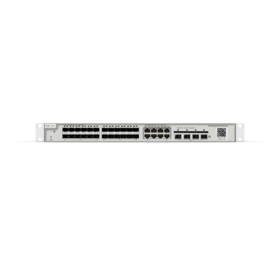
- Page 10 Ruijie RG-NBS3200 Series Switches Hardware Installation and Reference Guide Product Overview Front Panel Figure 1-6 Front Panel of the RG-NBS3200-24SFP/8GT4XS Note: 1. Reset button 4. Combo port 2. System status LED 5. 10GE SFP+ port 3. 1000Base-X SFP port 6. Nameplate on the bottom of the device The switch restarts after the reset button is pressed for less than 2 seconds.
- Page 11 Ruijie RG-NBS3200 Series Switches Hardware Installation and Reference Guide Product Overview The device must be intended to be used in a location with equipotential bonding (such as a telecommunication center, a dedicated computer room, or a restricted access area). Heat Dissipation The RG-NBS3200-24SFP/8GT4XS adopts fan for heat dissipation, thereby ensuring normal operation.
- Page 12 Flash Memory 256 MB SDRAM DDRIII 512 MB The copper cable is not supported. See Appendix B. Optical Module The supported module type may change at any time. Consult Ruijie Networks for the latest information. 10GBase-R SFP+ Port 1000Base-X ...
- Page 13 Ruijie RG-NBS3200 Series Switches Hardware Installation and Reference Guide Product Overview Dimensions 440 mm x 357.6 mm x 43.6 mm (with front panel) (W x D x H) Weight 4.75 kg Device operation in a residential environment may cause radio interference.
- Page 14 Ruijie RG-NBS3200 Series Switches Hardware Installation and Reference Guide Product Overview Press the PoE mode switchover button for over 3 seconds to switch the display mode between PoE mode and port rate mode. Back Panel Figure 1-11 Back Panel of the RG-NBS3200-24GT4XS-P Note: 1.
- Page 15 Flash Memory 256 MB SDRAM DDRIII 1GB The copper cable is not supported. See Appendix B. Optical Module The supported module type may change at any time. Consult Ruijie Networks for the latest information. 10GBase-R SFP+ Port 1000Base-X AC input...
- Page 16 Ruijie RG-NBS3200 Series Switches Hardware Installation and Reference Guide Product Overview Power 46 W Consumption Operating temperature: 0° C to 50° C (32° F to +122° F) Temperature Storage temperature: -40° C to +70° C (-40° F to +158° F)
- Page 17 Ruijie RG-NBS3200 Series Switches Hardware Installation and Reference Guide Product Overview Note: 1. Reset button 3. 10/100/1000 Base-T Ethernet port 2. System status LED 4. 10GE SFP+ port 5. Nameplate on the bottom of the device The switch restarts after the reset button is pressed for less than 2 seconds.
- Page 18 Built-in CPU, dual-core processor, and 1 GHz BootROM Flash Memory 256 MB SDRAM DDRIII 512 MB The copper cable is not supported. See Appendix B. Optical Module The supported module type may change at any time. Consult Ruijie Networks for the latest information. SFP+ Port 10GBase-R...
- Page 19 Ruijie RG-NBS3200 Series Switches Hardware Installation and Reference Guide Product Overview 1000Base-X AC input Rated voltage range: 100 V to 240 V Power Supply Maximum voltage range: 90 V to 264 V Frequency: 50/60 Hz Rated current: 7 A...
- Page 20 Ruijie RG-NBS3200 Series Switches Hardware Installation and Reference Guide Product Overview Front Panel Figure 1-18 Front Panel of the RG-NBS3200-48GT4XS-P Note: 1. PoE mode switch-over button 4. 10/100/1000 Base-T Ethernet port 2. System status LED 5. Reset button 3. Port mode LED 6.
- Page 21 Ruijie RG-NBS3200 Series Switches Hardware Installation and Reference Guide Product Overview Note: 1. Power cord retention clips 3. Protective earthing terminal 2. Three-hole AC power receptacle The device relies on the separate protective earthing terminal. The device installation must be permanently grounded.
- Page 22 Ruijie RG-NBS3200 Series Switches Hardware Installation and Reference Guide Product Overview Panel Identification State Meaning Solid green The switch is connected to Ruijie Cloud. Switching mode. Port mode LED LED mode Solid green PoE mode. The port is not connected.
-
Page 23: Preparation Before Installation
Ruijie RG-NBS3200 Series Switches Hardware Installation and Reference Guide Preparation Before Installation 2 Preparation Before Installation 2.1 Safety Suggestions To avoid personal injury and device damage, carefully read the safety suggestions before you install the RG-NBS3200 series. The following safety suggestions may not cover all possible dangers. - Page 24 Ruijie RG-NBS3200 Series Switches Hardware Installation and Reference Guide Preparation Before Installation action current of the leakage protector/2/maximum leakage current o f each power supply = 30/2/1.5 = 10). In other words, the leakage protector with 30 mA rated action current supports no more than ten power supplies. In this case, the twenty power supplies in the system require at least two leakage protectors with 30 mA r ated action current and each leakage protector supports ten power supplies.
- Page 25 Ruijie RG-NBS3200 Series Switches Hardware Installation and Reference Guide Preparation Before Installation The battery may e xperience an extremely high or low temperature or a low air pressure at a high altitude during use, storage or transportation. Leaving the battery in an e xtremely high temperature and/or low air pressure surrounding environment may result in an explosion or the leakage of flammable liquid or gas.
- Page 26 Ruijie RG-NBS3200 Series Switches Hardware Installation and Reference Guide Preparation Before Installation 2.2.3 Cleanness Dust poses a severe threat to the running of the device. The indoor dust falling on the device may be absorbed by the static electricity, causing bad contact of the metallic joint. Such electrostatic absorption may occur more easily when the relative humidity is low.
- Page 27 Ruijie RG-NBS3200 Series Switches Hardware Installation and Reference Guide Preparation Before Installation Effective grounding of the switch guarantees lightning protection and interference resistance. Therefore, connect the grounding line of the switch properly. Safety Grounding The device using AC power supply must be grounded by using the yellow/green safety grounding cable. Otherwise, when the insulating resistance decreases the power supply and the enclosure in the equipment, electric shock may occur.
-
Page 28: Installation Tools
Ruijie RG-NBS3200 Series Switches Hardware Installation and Reference Guide Preparation Before Installation 2.2.6 Lightning Resistance When the AC power cable is imported outdoors and directly connected to the power port of the RG-NBS3200 series switch, use the lightning line bank to prevent the switch from being hit by lightning shocks. In this case, connect the mains supply AC cable to the lightning line bank, and connect the switch to the lightning line bank. -
Page 29: Product Installation
Ruijie RG-NBS3200 Series Switches Hardware Installation and Reference Guide Product Installation 3 Product Installation 3.1 Installation Flowchart 3.2 Confirmations Before Installation Before installation, confirm the following points: Check whether ventilation requirements are met for the switch. - Page 30 Ruijie RG-NBS3200 Series Switches Hardware Installation and Reference Guide Product Installation Check whether the requirements of temperature and humidity are met for the switch. Check whether power cables are already laid out and whether the requirements of electrical c urrent are met.
- Page 31 Ruijie RG-NBS3200 Series Switches Hardware Installation and Reference Guide Product Installation Figure 3-3 Attaching the Brackets to the Rack 3.3.2 Mounting the Switch on a Table Attach the four rubber pads to the recessed areas on the bottom of the switch, as shown in Figure 3-4 and Figure 3-5.
-
Page 32: Grounding The Switch
Ruijie RG-NBS3200 Series Switches Hardware Installation and Reference Guide Product Installation Place the switch on the table, as shown in Figure 3-5. Figure 3-5 Mounting the Switch on the Table The device must be installed and operated in the place that can restrict its movement. -
Page 33: Connecting External Cables
Ruijie RG-NBS3200 Series Switches Hardware Installation and Reference Guide Product Installation The grounding electric resistance should be less than 1Ω. To guarantee the security of the body and the device, the switch must be well-grounded. The grounding resistance for combined grounding should be less than 1Ω. -
Page 34: Checking After Installation
Ruijie RG-NBS3200 Series Switches Hardware Installation and Reference Guide Product Installation 3.7 Checking After Installation Before checking the installation, switch off the power supply so as to avoid any personal injury or damage to the component due to connection errors . -
Page 35: System Commissioning
Ruijie RG-NBS3200 Series Switches Hardware Installation and Reference Guide System Commissioning 4 System Commissioning 4.1 Establishing the Configuration Environment Establishing the Configuration Environment Use the network cable to connect a PC to the switch. Figure 4-1 Configuration Environment Connecting the Console Cable ... - Page 36 Ruijie RG-NBS3200 Series Switches Hardware Installation and Reference Guide System Commissioning The console cable is correctly connected; the PC is already started; parameters are configured. Checking After Power-on (Recommended) After power-on, you are advised to perform the following checks to ensure the normal operation of follow -up configurations.
-
Page 37: Troubleshooting Flowchart
Ruijie RG-NBS3200 Series Switches Hardware Installation and Reference Guide Troubleshooting 5 Troubleshooting 5.1 Troubleshooting Flowchart 5.2 Troubleshooting Common Faults Symptom Possible Causes Solution management A password is manually configured but Press the reset button to restore the default interface login it is forgotten. - Page 38 Ruijie RG-NBS3200 Series Switches Hardware Installation and Reference Guide Troubleshooting Check whether the power socket is normal. The status LED is off The power supply is not enabled, or the Check whether the power cable is correctly after power-on. power cable is loosened.
-
Page 39: Appendix A Connectors And Connection Media
Ruijie RG-NBS3200 Series Switches Hardware Installation and Reference Guide Appendix A Connectors and Connection Media Appendix A Connectors and Connection Media 1000BASE-T/100BASE-TX/10BASE-T Ports The 1000BASE-T/100BASE-TX/10BASE-T supports adaptation of three rates and automatic MDI/MDIX crossover at these three rates. The 1000BASE-T complies with IEEE 802.3ab, and uses the cable of 100-ohm Category-5 or Supper Category-5 UTP or STP, which can be up to 100 m. - Page 40 Ruijie RG-NBS3200 Series Switches Hardware Installation and Reference Guide Appendix A Connectors and Connection Media Optical Fiber Connection For the optical fiber ports, select single-mode or multimode optical fibers for connection according to the fiber module connected. Figure A-4 shows the connection schematic diagram.
-
Page 41: Appendix B Mini-Gbic And Spf+ Module
You can select the mini-GBIC module to suit your specific needs. The models and technical specifications of some mini-GBIC and 10G SFP+ modules are listed below. For details, see Ruijie Transceiver Installation and Reference Guide. Table B-1 Models and Technical Specifications of the 1000M Mini-GBIC Module... - Page 42 Ruijie RG-NBS3200 Series Switches Hardware Installation and Reference Guide Appendix B Mini-GBIC and SPF+ Module GE-SFP-SX -9.5 GE-SFP-LX 1310 -9.5 SFP-MM850 -9.5 SFP-SM1310 1310 -9.5 Table B-2 Models and Technical Specifications of the Mini-GBIC-GT Module Standard 1000Base-T SFP Type DDM (Yes/No)
- Page 43 Ruijie RG-NBS3200 Series Switches Hardware Installation and Reference Guide Appendix B Mini-GBIC and SPF+ Module Rate/Distance Module Pairs GE-SFP-SX-SM1310-BIDI 1000 Mbps/500 m GE-SFP-SX-SM1550-BIDI GE-SFP-LX20-SM1310-BIDI 1000 Mbps/20 km GE-SFP-LX20-SM1550-BIDI GE-SFP-LH40-SM1310-BIDI 1000 Mbps/40 km GE-SFP-LH40-SM1550-BIDI XG-SFP-SR-SM1270-BIDI 10 Gbps/300 m XG-SFP-SR-SM1330-BIDI XG-SFP-LR-SM1270-BIDI 10 Gbps/10 km...
- Page 44 SFP+ 10.3125 Supported SFP+ models may change at any time. Contact Ruijie Networks after-sales personnel for the latest information. If the DDM function of the AOC cable does not report transmit power, the TX power is allowed to be disp layed as N/A.
-
Page 45: Appendix C Surge Protection
Ruijie RG-NBS3200 Series Switches Hardware Installation and Reference Guide Appendix C Surge Protection Appendix C Surge Protection Installing the AC Power Arrester (Surge Protection Cable Row) The external surge protection cable row must be used on the AC power port to prevent the sw itch from being struck by lightning when the AC power cable is introduced from the outdoor and directly connected to the power port of the switch. - Page 46 Ruijie RG-NBS3200 Series Switches Hardware Installation and Reference Guide Appendix C Surge Protection During the switch usage, the Ethernet port arrester must be connected to the switch to prevent the switch damage by lightning before the outdoor network cable connects to the switch.
- Page 47 Ruijie RG-NBS3200 Series Switches Hardware Installation and Reference Guide Appendix C Surge Protection Poor arrester grounding: The grounding line must be as short as possible to ensure that it is in good contact with the switch grounding terminal. Use the multimeter to confirm the contact after grounding.
-
Page 48: Appendix D Cabling Recommendations
Ruijie RG-NBS3200 Series Switches Hardware Installation and Reference Guide Appendix D Cabling Recommendations Appendix D Cabling Recommendations When RG-NBS3200 series switches are installed in standard 19-inch cabinets, cables are tied in the binding rack on the cabinet by the cabling rack, and top or bottom cabling is adopted according to the actual situation in the equipment room. - Page 49 Ruijie RG-NBS3200 Series Switches Hardware Installation and Reference Guide Appendix D Cabling Recommendations Route and bundle power, signal, ground cables separately. When the cables are close to each other, cross them. When power cables are parallel to signal cables, the distance between them must b e 30 mm (1.18 in.).
- Page 50 Ruijie RG-NBS3200 Series Switches Hardware Installation and Reference Guide Appendix D Cabling Recommendations Wrap up unnecessary or excess cables and bind them to the appropriate rack position, where device operation is not affected and no damages occur to the device and cables during commissioning.
- Page 51 Ruijie RG-NBS3200 Series Switches Hardware Installation and Reference Guide Appendix D Cabling Recommendations Diameter of Cable Bundle (mm) Space Between Bundles (mm) 80 to 150 10 to 30 150 to 200 200 to 300 No knot is allowed in cabling or bundling.
-
Page 52: Appendix E Site Selection
Ruijie RG-NBS3200 Series Switches Hardware Installation and Reference Guide Appendix E Site Selection Appendix E Site Selection The equipment room should be at least 5 km away from the heavy pollution source such as the smelter, coal mine , and thermal power plant, 3.7 km away from the medium pollution source such as the chemical industry, rubber...
Need help?
Do you have a question about the Reyee RG-NBS3200 Series and is the answer not in the manual?
Questions and answers