Ruijie Reyee RG-NBS3100-24GT4SFP-P-V2 Installation Manual
Hide thumbs
Also See for Reyee RG-NBS3100-24GT4SFP-P-V2:
- Release notes (10 pages) ,
- Configuration manual (297 pages)

Subscribe to Our Youtube Channel
Related Manuals for Ruijie Reyee RG-NBS3100-24GT4SFP-P-V2


Summary of Contents for Ruijie Reyee RG-NBS3100-24GT4SFP-P-V2
- Page 1 Ruijie Reyee RG-NBS3100-24GT4SFP-P-V2 Switch Installation Guide Document Version: V1.3 Date: May 10, 2024 Copyright © 2024 Ruijie Networks...
- Page 2 Ruijie Networks reserves the right to modify the content of the document without any notice or prompt. This manual is designed merely as a user guide. Ruijie Networks has tried its best to ensure the accuracy and reliability of the content when compiling this manual, but it does not guarantee that the content of the manual is completely free of errors or omissions, and all the information in this manual does not constitute any explicit or implicit warranties.
-
Page 3: Preface
Intended Audience This document is intended for: Network engineers Technical support and servicing engineers Network administrators Technical Support The official website of Ruijie Reyee: https://reyee.ruijie.com Technical Support Website: https://reyee.ruijie.com/en-global/support Case Portal: https://www.ruijienetworks.com/support/caseportal Community: https://community.ruijienetworks.com... - Page 4 Note This manual provides the device installation steps, hardware troubleshooting, module technical specifications, and specifications and usage guidelines for cables and connectors. It is intended for the users who have some experience in installing and maintaining network hardware. At the same time, it is assumed that the users are already familiar with the related terms and concepts.
-
Page 5: Table Of Contents
Contents Preface ..............................I 1 Product Overview ..........................1 1.1 Package Contents........................1 1.2 Technical Specifications ......................2 1.3 Appearance ..........................3 1.3.1 Front Panel ........................4 1.3.2 Rear Panel ........................5 1.4 Ventilation ..........................6 2 Preparing for Installation ........................7 2.1 Safety Precautions ........................ - Page 6 2.2.8 Lightning Resistance....................12 2.2.9 EMI ..........................12 2.2.10 Installation Tools ......................12 3 Product Installation .......................... 14 3.1 Installation Flowchart ....................... 14 3.2 Confirmations before Installation ..................... 14 3.3 Installing the RG-NBS3100...................... 14 3.3.1 Precautions ........................14 3.3.2 Mounting the Switch to a Standard 19-inch Rack ............15 3.3.3 Mounting the Switch on a Table ...................
- Page 7 6 Troubleshooting ..........................20 6.1 General Troubleshooting Flowchart ..................20 6.2 Troubleshooting Common Faults .................... 20 7 Appendix A Connectors and Connection Media ................22 8 Appendix B Mini-GBIC and SPF Module ..................24 9 Appendix C Lightning Protection ..................... 28 10 Appendix D Cabling Recommendations ..................
-
Page 8: Product Overview
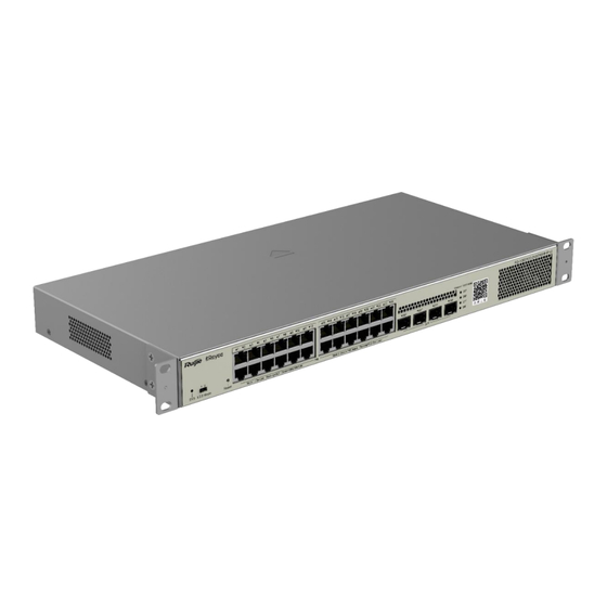
Product Overview Product Overview RG-NBS3100-24GT4SFP-P V2 is a new generation Ethernet switch developed by Ruijie Networks. The switch provides GE Ethernet ports and GE SFP ports and features high performance, high reliability and mutli-service integration. It adopts an efficient hardware architecture design for larger MAC address table capacity, higher hardware performance and more convenient experience. -
Page 9: Technical Specifications
SDRAM DDRIII 256 MB See Appendix B for details. Optical Module The supported optical module types may update without prior notice. Please contact Ruijie Networks for details. SFP Port SFP port is compliant with 1000Base-X and 100Base-X. AC input: Rated voltage range: 100 V AC to 240 V AC... -
Page 10: Appearance
Installation Guide Product Overview –40º C to +70º C (–40° F to +158° F) Storage Temperature Operating Humidity 10% to 90% RH (non-condensing) Storage Humidity 5% to 95% RH (non-condensing) Number of Fans One fan Temperature Alarming Not supported Certification Dimensions (W ×... -
Page 11: Front Panel
LED (SYS) Fast blinking (10 Hz): The switch is upgrading or restarting. Solid green: The switch is operating properly and connected to Ruijie Cloud. Toggle the switch to the left (Mode 1): The port status LED indicates the operating status of the switch. If the LED is solid green, the port is not sending and receiving data. -
Page 12: Rear Panel
Installation Guide Product Overview PoE status: Off: The PoE port is not supplying power. Solid green: The PoE port is supplying power. Blinking green: PoE overload occurs on the port. Port Status LED Port status: Off: The port is not connected. Solid green: The port has made a successful 10/100/1000 Mbps link, but it is not receiving or sending data. -
Page 13: Ventilation
Installation Guide Product Overview Ventilation The RG-NBS3100-24GT4SFP-P V2 switch adopts the side-to-rear airflow design to ensure that the switch works properly in the specified environment. Maintain a minimum clearance of 100 mm (3.94 in.) around the switch to ensure proper ventilation. You are advised to dust the switch at an interval of three months to avoid blocking the ventilation openings. -
Page 14: Preparing For Installation
Installation Guide Preparing for Installation Preparing for Installation Safety Precautions Note ● To avoid personal injury and device damage, carefully read the safety precautions before you install the switch. ● The following safety precautions may not cover all possible dangers. 2.1.1 Installation Safety ... -
Page 15: Electronic Static Discharge
Installation Guide Preparing for Installation maximum leakage current of all the power supplies in the system. For example, if a system is equipped with 16 identical power supplies, the leakage current of each power supply is at most 3.5 mA, and the leakage current of the system totals 56 mA (maximum theoretical value). A leakage protector with 30 mA rated action current supports less than nine power supplies (that is, Action current of the leakage protector/2/Maximum leakage current of each power supply = 30/2/3.5 ≈... -
Page 16: Installation Site Requirements
Installation Guide Preparing for Installation Installation Site Requirements To ensure the normal working and a prolonged durable life of the equipment, the installation site must meet the following requirements. 2.2.1 Ventilation For the RG-NBS3100 series, a sufficient space (at least 10 cm distances from both sides and the back plane of the cabinet) should be reserved at the ventilation openings to ensure the normal ventilation. -
Page 17: Interference Resistance
Installation Guide Preparing for Installation more easily when the relative humidity is low, not only affecting the useful life of the equipment, but also causing communication faults. Table 2-2 shows the requirements for the dust content and granularity in the equipment room. -
Page 18: Grounding
Installation Guide Preparing for Installation 2.2.5 Grounding A good grounding system is the basis for the stable and reliable operation of the RG-NBS3100 series switches. It is the chief condition to prevent lightning stroke and resist interference. Please carefully check the grounding conditions on the installation site according to the grounding requirements, and perform grounding operations properly as required. -
Page 19: Lightning Resistance
Installation Guide Preparing for Installation 2.2.8 Lightning Resistance When the AC power cable is imported outdoors and directly connected to the power port of the RG-NBS3100 series switch, lightning line bank should be adopted to prevent the switch from being hit by lightning shocks. Usage of the lightning line bank: Connect the mains supply AC cable to the lightning line bank. - Page 20 Installation Guide Preparing for Installation Common Phillips screwdriver, flathead screwdriver, related electric cables and optical cables, bolts, Tools diagonal pliers, straps Special Anti-static tools Tools Meters Multimeter Note The tool kit is customer-supplied.
-
Page 21: Product Installation
Installation Guide Product Installation Product Installation Note Please ensure that you have carefully read Chapter 2. Make sure that the requirements set forth in Chapter 2 have been met. Installation Flowchart Confirmations before Installation Before installation, please confirm the following points: ... -
Page 22: Mounting The Switch To A Standard 19-Inch Rack
Installation Guide Product Installation The power cables must be protected using power cable retention clips after they are connected to the device. Do not place any articles on the RG-NBS3100 series switch. Reserve a spacing of at least 10 cm around the chassis for good ventilation. Do not stack the devices. ... -
Page 23: Mounting The Switch On A Table
Installation Guide Product Installation 3.3.3 Mounting the Switch on a Table Attach the four rubber pads to the recessed areas on the bottom of the switch. Warning The device must be installed and operated in the place that can restrict its movement. 3.3.4 Grounding the Switch RG-NBS3100 has a PGND on the back panel. -
Page 24: Steps
Installation Guide Product Installation Avoid bends of small radius at the connector. 3.4.2 Steps Step 1: Connect one end of the Ethernet cable to the MGMT port of the device, and the other end to the NMS or a control terminal. Step 2: Insert the single-mode or multi-mode fiber into the appropriate port according to the identification on the panel of the module. -
Page 25: System Commissioning
Installation Guide System Commissioning System Commissioning Establishing the Configuration Environment Use the network cable to connect the PC to the switch. Figure 4-1 Configuration Environment Configuring the Device Step 1: Start the PC and configure the IP address of the PC as 10.44.77.XXX. (10.44.77.XXX indicates the IP address which is in the same network as the switch. -
Page 26: Power-On Startup
Installation Guide Power-on Startup Power-on Startup Checking before Power-on The switch is fully grounded. The power cable is correctly connected. The power cable is buckled after connected. The power supply voltage complies with the requirement of the switch. The console cable is correctly connected; the PC is already started; the parameters are already configured. Checking after Power-on (Recommended) After power-on, you are recommended to perform the following checks to ensure the normal operation of follow- up configurations. -
Page 27: Troubleshooting
Installation Guide Troubleshooting Troubleshooting General Troubleshooting Flowchart Troubleshooting Common Faults Symptom Possible Causes Solution Forgetting the management A password is manually Press the reset button to restore the default interface login configured but it is forgotten. settings. password Check whether the power socket is normal. The Status LED is The power supply is not enabled, Check whether the power cable is correctly... - Page 28 Installation Guide Troubleshooting The Rx and Tx ends are Switch the Rx and Tx ends of the optical connected reversely. fiber. The interconnected optical Replace the optical module with one of the The fiber port module type does not match. matched type.
-
Page 29: Appendix A Connectors And Connection Media
Installation Guide Appendix A Connectors and Connection Media Appendix A Connectors and Connection Media 1000BASE-T/100BASE-TX/10BASE-T Ports The 1000BASE-T/100BASE-TX/10BASE-T is a port that supports adaptation of three rates, and automatic MDI/MDIX Crossover at these three rates. The 1000BASE-T complies with IEEE 802.3ab, and uses the cable of 100-ohm Category-5 or Supper Category-5 UTP or STP, which can be up to 100 m. - Page 30 Installation Guide Appendix A Connectors and Connection Media Optical Fiber Connection For the optical fiber ports, select single-mode or multiple-mode optical fibers for connection according to the fiber module connected. The connection schematic diagram is shown in Figure A-4: Figure A-4 Schematic Diagram for optical fiber connection...
-
Page 31: Appendix B Mini-Gbic And Spf Module
Installation Guide Appendix B Mini-GBIC and SPF Module Appendix B Mini-GBIC and SPF Module SFP modules (Mini-GBIC module) are available to address the requirements of interface types of switch modules. You can select the Mini-GBIC or SFP+ module to suit your specific needs. The models and technical specifications of some Mini-GBIC and SFP modules are listed below for your reference. - Page 32 Installation Guide Appendix B Mini-GBIC and SPF Module GE-SFP-LH40- 1550TX/1310R SM1550-BIDI MINI-GBIC- 1550 ZX50-SM1550 MINI-GBIC- 1550 ZX80-SM1550 MINI-GBIC- 1550 ZX100-SM1550 GE-SFP-SX -9.5 GE-SFP-LX 1310 -9.5 SFP-MM850 -9.5 SFP-SM1310 1310 -9.5 Table B-2 Models and Technical Specifications of the Mini-GBIC-GT Module Standard 1000Base-T SFP Type DDM (Yes/No)
- Page 33 Installation Guide Appendix B Mini-GBIC and SPF Module GE-SFP-SX-SM1550- 50/125 500m BIDI GE-SFP-LX20-SM1310- 9/125 20km BIDI GE-SFP-LX20-SM1550- 9/125 20km BIDI GE-SFP-LH40-SM1310- 9/125 40km BIDI GE-SFP-LH40-SM1550- 9/125 40km BIDI MINI-GBIC-ZX50- 9/125 50km SM1550 MINI-GBIC-ZX80- 9/125 80km SM1550 MINI-GBIC-ZX100- 9/125 100km SM1550 62.5/125 275m GE-SFP-SX...
- Page 34 Installation Guide Appendix B Mini-GBIC and SPF Module GE-SFP-LH40-SM1310-BIDI 1000M /40km GE-SFP-LH40-SM1550-BIDI Caution The BIDI modules must be used in pairs (e.g., GE-SFP-LX20-SM1310-BIDI and GE-SFP-LX20-SM1550-BIDI).
-
Page 35: Appendix C Lightning Protection
Installation Guide Appendix C Lightning Protection Appendix C Lightning Protection Installing AC Power Arrester (lightning protection cable row) The external lightning protection cable row shall be used on the AC power port to prevent the switch from being struck by lightning when the AC power cable is introduced from the outdoor and directly connected to the power port of the switch. - Page 36 Installation Guide Appendix C Lightning Protection During the switch usage, the Ethernet port arrester shall be connected to the switch to prevent the switch damage by lightning before the outdoor network cable connects to the switch. Tools: Cross or straight screwdriver, Multimeter, Diagonal pliers Installation Steps: ...
- Page 37 Installation Guide Appendix C Lightning Protection Arrester Hardware Installation Guide, which contains the technical specification and the maintenance and installation of the arrester. You may pay attention to the following conditions during the actual installation to avoid influencing the performance of the Ethernet port arrester: ...
-
Page 38: Appendix D Cabling Recommendations
Hardware Installation and Reference Guide Appendix D Cabling Recommendations Appendix D Cabling Recommendations When RG-NBS3100 series switches are installed in standard 19-inch racks, route cable bundles upward or downward along the sides of the rack depends on the actual situation in the equipment room. All cable connectors should be placed at the bottom of the rack rather than be exposed outside of the cabinet. - Page 39 Installation Guide Appendix D Cabling Recommendations them. When power cables run parallel to signal cables, the distance between them must b All cable trays and their accessories shall be smooth and free from sharp edges. Holes in metal, through which cables pass shall have smooth, well-rounded surfaces or be protected with insulating bushings.
- Page 40 Installation Guide Appendix D Cabling Recommendations avoid stress on the cable; when moving parts are in place, ensure the excess cable length shall not contact heat sources, sharp corners or edges. If heat sources are unavoidable, use high-temperature cables instead. ...
-
Page 41: Appendix E Site Selection
Installation Guide Appendix E Site Selection Appendix E Site Selection The machine room should be at least 5km away from the heavy pollution source such as the smelter, coal mine and thermal power plant, 3.7km away from the medium pollution source such as the chemical industry, rubber industry and electroplating industry, and 2km away from the light pollution source such as the food manufacturer and leather plant.
Need help?
Do you have a question about the Reyee RG-NBS3100-24GT4SFP-P-V2 and is the answer not in the manual?
Questions and answers