Table of Contents
Advertisement
Quick Links
Advertisement
Table of Contents

Related Manuals for TEXIO PSW-A Series


Summary of Contents for TEXIO PSW-A Series
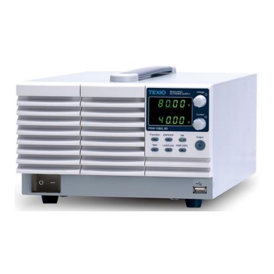
- Page 1 INSTRUCTION MANUAL Multi-Range DC Power Supply PSW-A Series PSW-360L30A PSW-720L30A PSW-1080L30A PSW-360L80A PSW-720L80A PSW-1080L80A PSW-360M160A PSW-720M160A PSW-1080M160A PSW-360M250A PSW-720M250A PSW-1080M250A PSW-360H800A PSW-720H800A PSW-1080H800A B71-0532-01...
-
Page 2: Table Of Contents
CONTENTS USING THE PRODUCT SAFELY…………………………………………………Ⅰ-Ⅳ GETTING STARTED ..............5 1.1. PSW-A Series Overview ..............5 1.1.1. Series lineup (Total 15 models) ..........5 1.1.2. Main Features ................ 6 1.1.3. Accessories ................7 1.2. Appearance ..................9 1.2.1. Front Panel ................9 1.2.2. - Page 3 2.2.3. Set to CC Mode ..............45 2.2.4. Set to CP Mode ..............47 2.2.5. Display Modes ..............48 2.2.6. Panel Lock ................48 2.2.7. Remote Sense ..............49 2.3. One-control parallel operation ............51 2.3.1. Overview of one-control parallel operation ......51 2.3.2.
- Page 4 3.4.1. Factory Set Value ..............73 3.4.2. Show Version ..............73 3.5. Function settings at power-on ............74 3.5.1. Voltage setting Control ............74 3.5.2. Current setting Control ............74 3.5.3. Power-ON Output ..............75 3.5.4. External Out Logic ............... 75 3.5.5.
- Page 5 5.1.3. External Resistance Control of Voltage Output ....112 5.1.4. External Resistance Control of Current Output ....113 5.1.5. External output on ............. 115 5.1.6. Output off by external control ..........117 5.2. Monitor output ................118 5.2.1. Output voltage and output current monitor signals .... 118 5.2.2.
- Page 6 Even if there is a description attached to the instruction manual, it may not be attached. The latest version of the instruction manual is posted on our website (https://www.texio.co.jp/download/). ■ About firmware version The contents described in this document apply to PSW-Multi series main unit firmware version 2.03...
- Page 7 USING THE PRODUCT SAFELY ■ Preface To use the product safely, read this instruction manual to the end. Before using this product, understand how to correctly use it. ask us or your local If you read this manual but you do not understand how to use it, dealer.
- Page 8 USING THE PRODUCT SAFELY WARNING ■ Do not remove the product's covers and panels Never remove the product's covers and panels for any purpose. Otherwise, the user's electric shock or a fire may be incurred. ■ Warning on using the product The warning items given below are to avoid danger to the user's body and life and avoid the damage and deterioration of the product.
- Page 9 USING THE PRODUCT SAFELY WARNING ■ Warning item on installation environment ● Operating temperature Use the product within the operating temperature indicated in the rating column. If the product is used with the vents of the product blocked or in high ambient temperatures, a fire may occur.
- Page 10 USING THE PRODUCT SAFELY CAUTION ■ Input/output terminal Maximum input to the input terminals is specified to prevent the product from being damaged. Do not supply input, exceeding the specifications that are indicated in the "Rating" or "Caution on use" column in the instruction manual of the product.
-
Page 11: Using The Product Safely
1.1. PSW-A Series Overview 1.1.1. Series lineup (Total 15 models) This product series is equipped with five types of voltage units (30V, 80V, 160V, 250V, 800V) with different rated output voltages in three types of housings (Type I, II, III). -
Page 12: Main Features
1.1.2. Main Features Performance ⚫ High performance/power ⚫ Power efficient switching type power supply ⚫ Low impact on load devices ⚫ Fast transient recovery time of 1ms ⚫ Fast output response time Features ⚫ OVP, OCP, OHP (OTP) and tUVP protection ⚫... -
Page 13: Accessories
1.1.3. Accessories Please check the contents before using this product. Standard Accessories Part number Description Power cord Varies by region and TYPE. Output terminal covers for low voltage models PSW-009* Output terminal covers for high voltage models PSW-011* Output terminals for high voltage models PSW-012*... - Page 14 Optional Accessories Part number Description GET-001 Extended terminal with max. 30A GET-002 Extended European terminal with max. 10A PSW-001 Accessory Kit: Pin contact x10, Socket x1, Protection cover x1 GRA-410-J Rack mount adapter (JIS) GRA-410-E Rack mount adapter (EIA) GUG-001 GPIB to USB adapter GTL-130 Test leads for high voltage modules: 1x red, 1x black...
-
Page 15: Appearance
1.2. Appearance 1.2.1. Front Panel 720W models PSW-720****A (TypeII) Multi- Range DC Power Supply Voltage Voltage 720W Display knob Current Current knob Cover panel Output Function OVP/ OCP Output Test Lock/ Local PWR DSPL Power Function switch keys USB A port 1080W, 360W models PSW-1080****A (TypeIII) - Page 16 Front panel description Name Symbol Description Voltage Knob Sets the voltage. When pressed, the variable digit changes. Variable digits are displayed brighter than other digits. Current Knob Sets the current. When pressed, the variable digit changes. Variable digits are displayed brighter than other digits.
- Page 17 Set key Sets the current and voltage limits. Test key Used to run customized scripts for testing. Lock/Local key Panel key lock and unlock. Lock/Local Locks prevent accidental changes to panel settings. PWR DSPL key Switch the display between V/A and V/W or A/W.
-
Page 18: Rear Panel
1.2.2. Rear Panel Low voltage 720W models PSW-720M160A, PSW-720L80A, PSW-720L30A (Type II) Analog control Sense+ USB B Output connector terminal Port terminal(+) Sense- terminal SER.NO. LABEL Output terminal(-) 240V 47 63Hz 1000VA MAX. AC Input Low voltage 1080W, 360W models PSW-1080M160A, PSW-360M160A, PSW-1080L80A,... - Page 19 High voltage 720W models PSW-720H800A, PSW-720M250A (Type II) Sense+ USB B Output Analog control terminal port terminals +V connector Sense- terminal SN.C. S SER.NO. LABEL Chassis ground Output terminals -V 240V 47 63Hz 1000VA MAX. AC Input High voltage 1080W, 360W models PSW-1080H800A, PSW-360H800A, PSW-1080H250A...
- Page 20 Rear panel description Name Symbol Description LAN Port The ethernet port is used for remote control and digital monitoring from a controller. Output Terminals Positive (+) and negative (Low-volt model) (-) output terminals. Chassis ground Sense (-S) and Sense (+S) terminals. Output Terminals High voltage models use 9-pin connectors (High-volt model)
- Page 21 Line Voltage Input Voltage Input: 100~240 360W, 720W models Line frequency: 50Hz/60 Line Voltage Input 1080W models...
-
Page 22: Theory Of Operation
1.3. Theory of Operation The theory of operation chapter describes the basic principles of operation, protection modes and important considerations that must be taken into account before use. 1.3.1. Operating Area Description This product is regulated DC power supplies with a high voltage and current output. - Page 23 30V model operating area Type I Type II Type III Current(A) 80V model operating area 9.0 13.5 40.5 Type I Type II Type III 26.6 Current(A) 160V model operating area 2.25 4.5 6.75 14.4 21.6 Type I Type II Type III Current(A)
- Page 24 250V model operating area 1.44 2.88 4.32 13.5 Type I Type II Type III Current (A) 800V model operating area 0.45 0.9 1.35 1.44 2.88 4.32 Type I Type II Type III Current (A)
-
Page 25: Cc And Cv Mode
1.3.2. CC and CV Mode Crossover >R point <R When the power supply is operating in constant current mode (CC) a constant current will be supplied to the load. When in constant current mode the voltage output can vary, whilst the current remains constant. When the load resistance increases to the point where the current limit (ISET) can no longer be sustained the power supply switches to CV mode. -
Page 26: Slew Rate
1.3.3. Slew Rate This product has selectable slew rates for CC and CV mode. Slew rate settings are divided into High-Speed Priority and Slew Rate Priority. High-Speed Priority mode disables slew rate settings for CC or CV mode. Slew Rate Priority mode allows for user adjustable slew rates for CC or CV mode. - Page 27 PSW-360L30A sink current Vout (V) Bleeder ON (A) Bleeder OFF (mA) 1.455 0.000 1.733 0.000 1.559 0.002 1.123 0.009 0.715 0.014 0.471 0.021 0.353 0.031 0.267 0.038 PSW-360L80A sink current Vout (V) Bleeder ON (A) Bleeder OFF (mA) 0.640 0.002 0.589 0.009 0.488...
- Page 28 PSW-360M250A sink current Vout (V) Bleeder ON (A) Bleeder OFF (mA) 0.158 0.031 0.143 0.098 0.129 0.164 0.107 0.267 0.092 0.333 0.061 0.508 0.463 0.697 0.035 0.961 PSW-360H800A sink current Vout (V) Bleeder ON (A) Bleeder OFF (mA) 0.061 0.056 0.058 0.138 0.054...
-
Page 29: Internal Resistance
1.3.5. Internal Resistance This product can set the internal resistance of the output. (Internal Resistance Setting, refer to page 61). When the internal resistance is set it can be seen as a resistance in series with the positive output terminal. This allows this product to simulate power sources that have internal resistances such as lead acid batteries. -
Page 30: Protection Function
1.3.6. Protection function This product has many protection features. When any protection function is activated, the ALM icon on the display lights up. For details on how to set up protection functions, refer to Overvoltage protection (OVP) prevents a high voltage from damaging the load. - Page 31 the indicated value. For pulsed loads, the current limit must be increased, or a power supply with a greater capacity must be chosen. As shown below, a pulsed load may exceed the current limit and the indicated current on the power supply ammeter. Current limit level Measured...
-
Page 32: Output Grounding
this product and load. Ensure the reverse withstand voltage of the diode is Caution able to withstand 2 times the rated output voltage of the power supply and the forward current capacity can withstand 3 to 10 times the rated output current of the power supply. - Page 33 voltage control, external resistance control, etc., the control signal should be floating instead of grounded. If it is grounded, the output will short-circuit and cause an accident. Grounded output When the positive or negative terminal is connected terminal to the protective ground terminal, the insulation capacity needed for the load and load cables is greatly reduced.
-
Page 34: Operation
2. OPERATION 2.1. Set Up 2.1.1. Line Voltage Connection: 1080W Models The 1080 models use a universal power input that can be used with 100 and 200 VAC systems. To connect or replace the power cord, use the procedure below: The following procedure should only be attempted by Warning competent persons. -
Page 35: Filter Installation
How to attach the AC cord steps Installation procedure Connect the AC power cord wires to the AC input terminals. White/Blue → Neutral (N) Green/Green-yellow→GND ( Black/Brown → Line (L) Set the cover back over the AC terminals. Secure the AC terminal protection cover with screws. -
Page 36: Power Up
2.1.3. Power Up steps Step instructions 360W, 720W model: Connect the power cord to the AC inlet on the back panel. 1080W model: Refer to page 28. Connect the power cord to the AC input terminal on the back panel. Press the POWER switch. -
Page 37: Output Terminals: Low Voltage Model
AWG 12 3.5 / 3.31 37 A AWG 10 5.5 / 5.26 49 A AWG 8 8 / 8.37 61 A AWG 6 14 / 13.3 88 A AWG 4 22 / 21.15 115 A AWG 2 38 / 33.63 162 A AWG 1 38 / 42.41... -
Page 38: Attaching Output Terminal Cover: Low Voltage Model
Choose a suitable crimp terminal for the terminals. When using voltage sense, remove the Refer to page 49. sense terminal joining plates and connect sensing wires to the load(s). Connect the positive load cable to the positive output terminal and the negative cable to the negative output terminal. Reattach the output terminal cover. -
Page 39: Output Terminals: High Voltage Model
Slide the top cover to integrate with the bottom cover. When the top and bottom covers are flush, re-insert the screw that was removed in step 1. Reverse the procedure to remove the terminal Note covers. 2.1.7. Output Terminals: High voltage model High voltage models use the supplied 9-pin socket for output voltage and sense connections. - Page 40 Output Connector When using the output connector make sure the Overview wires that are used follow the following guidelines: Wire gauge: AWG 26 to AWG 16 Strip length: 6.5mm // 0.26 in. Current rating: 10A Insulation withstand voltage: >2000MΩ DC500V Operation Temperature: -40ºC to +105ºC Output Connector -V: -V terminals (x3)
- Page 41 When using local sense, connect the -S pin to a -V pin, and connect the +S pin to a +V pin. SN.C. S When not using local sense, see the Refer to page 49. remote sense section to wire the sense terminals for remote sensing.
-
Page 42: Attaching Output Terminal Cover: High Voltage Model
2.1.8. Attaching output terminal cover: High voltage model steps Step instructions Screw the bottom cover onto the rear panel using the two M4 screws. Slide the top cover over the bottom cover. Finally, secure the top and bottom covers using the screw in the center of the top cover. -
Page 43: Useing The Voltage And Current Knob
2.1.10. Useing the Voltage and Current knob This product use voltage or current knobs to set parameter values. Press the voltage or current knob to select the setting digit of the parameter value. Example Use the Voltage knob to set a voltage of 10.05 V. steps Step instructions Press the voltage knob repeatedly until the 0.01... -
Page 44: Reset To Factory Default Settings
2.1.11. Reset to Factory Default Settings This product can be reset to factory default settings. For factory default settings, see page 136. steps Step instructions Press the Function key. The Function key will light up. The display should show F-01 on the top and the configuration setting for F-01 on the bottom. - Page 45 Rotate the Voltage knob to change the F setting to F-89 (Show Version). Turn the current knob to display the firmware version and system information. F-89 0-XX Firmware version number 1-XX Firmware version number 2-XX Firmware build: Year 3-XX Firmware build: Year 4-XX Firmware build: Month 5-XX...
- Page 46 0-01 Version number 1.50 1-50 2-20 Build: Year 2014 3-14 4-01 Build: Month - Day. 01-13 5-13 Example Keyboard CPLD information: 0x030c 6-03 Version number 030c 7-0c Example Analog control CPLD information: 0x0427 8-04 Version number 0427 9-27 Example Control Board information: XX A-XX Version number Example...
-
Page 47: Basic Operation
2.2. Basic Operation This section describes the basic operations required to operate this product. Before operating this product, please refer to the Getting Started chapter (page 5). 2.2.1. Setting OVP/OCP Levels For most models the OVP level has a selectable range of approximately 10% to 110% of the rated output voltage. - Page 48 Press OVP/OCP again to exit. The OVP/OCP indicator will turn off. Power switch trip setting The power switch of this product is not a trip type switch. Note Even if this setting is enabled, the power switch will not turn off. steps Step instructions While holding down the Function key, turn...
-
Page 49: Set To Cv Mode
2.2.2. Set to CV Mode When setting the power supply to constant voltage mode, a current limit must also be set to determine the crossover point. When the current exceeds the crossover point, the mode switches to CC mode. For details about CV operation, refer to page 19. - Page 50 250V 0.1V/s ~ 500.0V/s 800V 1V/s ~ 1600V/s Press the Function key again to exit the configuration settings. The function key light will turn off. Use the Current knob to set the current limit (crossover point). Use the Voltage knob to set the voltage. When the set value is displayed on the display, the Set Note key lights up.
-
Page 51: Set To Cc Mode
2.2.3. Set to CC Mode When setting the power supply to constant current mode, a voltage limit must also be set to determine the crossover point. When the voltage exceeds the crossover point, the mode switches to CV mode. For details about CC operation, refer to page 19. - Page 52 PSW-360L80A 0.01A/s ~ 27.00A/s PSW-720L80A 0.01A/s ~ 54.00A/s PSW-1080L80A 0.01A/s ~ 81.00A/s PSW-360M160A 0.01A/s ~ 14.40A/s PSW-720M160A 0.01A/s ~ 28.80A/s PSW-1080M160A 0.01A/s ~ 43.20A/s PSW-360M250A 0.001A/s ~ 9.000A/s PSW-720M250A 0.01A/s ~ 18.00A/s PSW-1080M250A 0.01A/s ~ 27.00A/s PSW-360H800A 0.001A/s ~ 2.880A/s PSW-720H800A 0.001A/s ~ 5.760A/s PSW-1080H800A...
-
Page 53: Set To Cp Mode
When the output is turned on, the display becomes the Note output value. When the Set key is pressed, the display will show the set value. For more information on the Normal Function Settings (F-00 ~ F-61, F-88~F-89) refer to page 66. 2.2.4. -
Page 54: Display Modes
The constant power value is not initialized even when aution initializing with F-88 or using the *RST command. Operation may become unstable if the constant power value is less than 10% of the rated power or the current output value is less than 10% of the rated current. 2.2.5. -
Page 55: Remote Sense
Activate the panel lock Press the Lock/Local key to active the panel lock. The key will become illuminated. Disable the panel lock Hold the Lock/Local key for ~3 seconds to disable the panel lock. The Lock/Local light turns off. When panel lock is enabled, the output key operation Note content changes depending on the setting status of basic function "F-19". - Page 56 Independent operation connection Connect the Sense+ terminal to the positive potential of the load. Connect the Sense- terminal to the negative potential of the load. PSW #1 Load Parallel operation connection Connect all Sense+ terminals to Output Input the positive potential of the load. Output Input Connect all Sense- terminals to...
-
Page 57: One-Control Parallel Operation
Capacitor To help to minimize the oscillation due to the inductance and capacitance of the load cables, use an electrolytic capacitor Load in parallel with the load terminals. To minimize the effect of load line impedance, use twisted wire pairing. Twisted pair 2.3. - Page 58 Output External voltage or external resistance can be input voltage/current as external signal. control by external Output voltage/current control using external signal input signals is valid only for the master unit. Internal resistance When two units are connected in parallel, the value setting value will be half (1/2) of the value set on the master unit.
-
Page 59: Wiring For One-Control Parallel Operation
2.3.2. Wiring for one-control parallel operation When using this product in one-control parallel operation, wiring to connect this product to the load and control signal wiring between the master unit and slave units of this product are required. steps Step instructions Turn off the power to all this product. - Page 60 Control signal wiring between master unit and slave unit (1 unit) 1715 24 20 Master unit Slave Unit 1 I MON CURRENT SHARE OUTPUT ON STATUS OUT ON/ OFF CONT ALM STATUS SHUTDOWN STATUS COM STATUS COM FEEDBACK FEEDBACK CURRENT_SUM_1 CURRENT SUM OUT SHUTDOWN ALM STATUS...
-
Page 61: Settings And Checking For One-Control Parallel Operation
2.3.3. Settings and checking for one-control parallel operation When using this product in one-control parallel operation, set the master and slave units for this product. This product allows one-control parallel operation with a configuration of only the same model. steps Step instructions From the power off state of this product, turn it on while pressing the Function key. -
Page 62: One-Control Series Operation
Turn off the power to this product and Refer to page check that the various wiring between the master and slave units is properly connected. Turn on the power of the master and slave units. The slave units will display "- - - -". Master unit Slave unit The master unit can perform various... - Page 63 product in series. Please read this overview carefully before beginning series operation of this product. Limitations Description Display Only the master unit displays the current value. The voltage value is displayed on both the master and slave units. For the voltage value, add the voltages of the master and slave units.
-
Page 64: Wiring For One-Control Series Operation
PSW-720M160A 160V, 14.4A 320V, 14.4A PSW-1080L30A 30V, 108A 60V, 108A PSW-1080L80A 80V, 40.5A 160V, 40.5A PSW-1080M160A 160V, 21.6A 320V, 21.6A 2.4.2. Wiring for one-control series operation When using this product in one-control series operation, wiring to connect this product to the load and control signal wiring between the master unit and slave units of this product are required. -
Page 65: Settings And Checking For One-Control Series Operation
Control signal wiring between master unit and slave unit (1 unit) Master Slave A COM SER SLV IN OUTPUT ON STATUS OUT OFF/ON CONT ALM STATUS SHUTDOWN STATUS COM D COM SHUTDOWN ALM STATUS D COM STATUS COM The above wiring can be done using the optional product PSW-005. 2.4.3. - Page 66 F93: 0 Master unit F93: 4 Slave unit Be sure to set only one master unit. Do not set multiple master units. Caution In addition, set all devices other than the master device as slave devices. Press the voltage knob to confirm the configuration setting.
-
Page 67: Function Settings
3. Function settings The function settings of this product include various function settings, digital communication settings, external analog settings, power-on settings, calibration settings, etc. External analog settings can only be set when the power switch is on. Other settings can be configured while operating this product. 3.1. -
Page 68: Usb & Gp-Ib
Bleeder circuit control F-09 0: OFF, 1: ON, 2: AUTO Buzzer ON/OFF control F-10 0: OFF, 1: ON Measurement Average F-17 0: Low, 1: Middle, 2: High Output key operation F-19 0: allow output off (In panel lock active) 1: allow output on/off 3.1.2. -
Page 69: Uart (Rs-232C)
Web setting password F-61 0000~9999 3.1.4. UART (RS-232C) Settings for this item have *3 restrictions. Item Setting Setting Range UART Baud Rate F-71 0: 1200, 1: 2400, 2: 4800, 3: 9600 (Unit: bps) 4: 19200, 5: 38400, 7: 115200 UART Data Bits (Unit: bit) F-72 0: 7, 1: 8 UART Parity F-73... -
Page 70: Tuvp Function
Current set value fixed F-86 0: Set digit operation disabled 1: Set digit operation enabled 3.1.8. tUVP function Please refer to page for how to set this function. Item Setting Setting Range Enable/ Disable F-A0 0: Disable 1: Enable, compare by instantaneous value voltage 2: Enable, compare by average value voltage... -
Page 71: Calibration
Voltage settings F-90 0: Panel control (local) 1: External voltage control 2: External resistance control 1 10kΩ = V ratings) (Ext-R 3: External resistance control 2 10kΩ = 0V) (Ext-R Current settings F-91 0: Panel control (local) 1: External voltage control 2: External resistance control 1 10kΩ... -
Page 72: Normal Function Settings
3.2. Normal Function Settings 3.2.1. Output ON/OFF Delay Time Delays turning the output on or off for the specified amount of time. Item Setting Setting Range Output ON Delay Time F-01 0.00s ~ 99.99s Output OFF Delay Time F-02 0.00s ~ 99.99s The “DLY”... - Page 73 Item Setting Voltage models Setting Range Rising voltage F-04 0.01V/s ~ 60.00V/s slew rate 0.1V/s ~ 160.0V/s 0.1V/s ~ 320.0V/s 0.1V/s ~ 500.0V/s 1V/s ~ 1600V/s Falling voltage F-05 0.01V/s ~ 60.00V/s slew rate 0.1V/s ~ 160.0V/s 0.1V/s ~ 320.0V/s 0.1V/s ~ 500.0V/s 1V/s ~ 1600V/s The current slew rate can be set when the V-I mode slew rate is set to “CC...
-
Page 74: Internal Resistance Setting
PSW-1080L30A 0.1A/s ~ 216.0A/s PSW-360L80A 0.01A/s ~ 27.00A/s PSW-720L80A 0.01A/s ~ 54.00A/s PSW-1080L80A 0.01A/s ~ 81.00A/s PSW-360M160A 0.01A/s ~ 14.40A/s PSW-720M160A 0.01A/s ~ 28.80A/s PSW-1080M160A 0.01A/s ~ 43.20A/s PSW-360M250A 0.001A/s ~ 9.000A/s PSW-720M250A 0.01A/s ~ 18.00A/s PSW-1080M250A 0.01A/s ~ 27.00A/s PSW-360H800A 0.001A/s ~ 2.880A/s PSW-720H800A... -
Page 75: Bleeder Circuit Control
3.2.4. Bleeder circuit control Bleeder circuit control turns the bleeder circuit ON/OFF. When set to AUTO, the bleeder circuit turns on when the output is on and turns off when the output or power is turned off. Refer to page for usage details. -
Page 76: Usb/Gpib/Uart/Lan Settings
3.3. USB/GPIB/UART/LAN Settings 3.3.1. USB setting Displays the usage status of the front and rear panel USB A ports and configures the rear panel USB. Front Panel USB State Setting Setting Range Displays the front panel F-20 0: Absent USB-A port state. 1: USB memory exists (Only confirmation) Rear Panel USB State... -
Page 77: Lan Settings
3: 9600 4: 19200 5: 38400 6: 57600 7: 115200 UART Data Bits Setting Setting Range Set data bits F-72 0: 7 (Unit: bit) 1: 8 UART Parity Setting Setting Range Set parity F-73 0: None 1: Odd 2: Even UART Stop Bit Setting Setting Range Set stop bit... - Page 78 IP Address-2 F-40 0 ~ 255 IP Address-3 F-41 0 ~ 255 IP Address-4 F-42 0 ~ 255 Set arbitrary values for IP addresses-1~4. Sets the subnet mask Setting Setting Range Subnet Mask-1 F-43 0 ~ 255 Subnet Mask-2 F-44 0 ~ 255 Subnet Mask-3 F-45...
-
Page 79: System Settings
Web password active F-60 0: Disable 1: Enable Sets the Web password Setting Setting Range Web password F-61 0000~9999 3.4. System Settings 3.4.1. Factory Set Value Returns this product to the factory default settings. Refer to page for a list of the default settings. Item Setting Setting Range Sets factory value... -
Page 80: Function Settings At Power-On
M, N: USB Driver version number 3.5. Function settings at power-on Power on configuration settings only can be set during power up. 3.5.1. Voltage setting Control Set voltage setting control using either panel control or external voltage/resistance control. For external voltage control, refer to page (External Voltage Control of Voltage Output) and page (External Resistance Control of Voltage Output). -
Page 81: Power-On Output
3.5.3. Power-ON Output Configures this product to do one of the following at startup. Item Setting Setting Range Power-ON Output F-92 0: OFF at startup 1: ON at startup T001 ~ T010: Run test script TXX at start up 3.5.4. External Out Logic Set the logic for turning on the output using an external control. -
Page 82: Setting Power On Configuration Settings
Ensure the output is off. steps Step instructions Press the Function key. The function key will light up. The display will show F-01 on the top and the configuration setting for F-01 on the bottom. Rotate the Voltage knob to change the Voltage F-XX setting. - Page 83 The display of all channel will show F-90 on the top and the configuration setting for F-90 on the bottom. Rotate the Voltage knob to change the Voltage F-XX setting. F-XX: F-90~ F-95 Current Use the Current knob to set the parameter for the chosen F setting.
-
Page 84: Special Functions
4. Special functions 4.1. Cooling fan stop function This function temporarily stops the operation of the cooling fan. Use this when there is a problem with fan operation. Continuous operation with the cooling fan stopped is not possible. After the cooling fan is stopped, the cooling fan stop function is disabled for the fan stop time. -
Page 85: Executing The Fan Stop Function
4.1.2. Executing the fan stop function The fan stop function can be selected from two types of operation: Execute one action and executing automatic actions. steps Step instructions Press the Function key. The Function key will light up. Rotate the Voltage knob to change the F setting to F-80. -
Page 86: Logging Function
Press the voltage knob to execute the fan stop function. "ConF" → "3" is displayed at the bottom of the display, and the fan stops and operates repeatedly at the set time interval. If the fan stop function is executed automatically, the automatic execution will not stop even if finish setting the Note fan stop time. -
Page 87: Logging Function Operation: Usb Memory
Press the voltage knob to determine the logging time interval. When the settings are confirmed, “ConF” will be displayed. Press the Function key to finish setting the logging time interval. The Function key turns off. When outputting logging data via digital communication, you can use the logging time interval setting command Note (SENSe:DLOG:PERiod). - Page 88 Logging data storage folder selection operation Press the Function key. The Function key will light up. Rotate the Voltage knob to change the F setting to F-84. F-84: Logging data storage folder select Use the Current knob to set the F-84 setting.
- Page 89 In step 8, press the Function key to turn off the key and complete the logging function settings. At this time, the Note logging function is still operating even if the logging function settings have been completed. This product can be operated while the logging function is in operation (voltage display blinking).
-
Page 90: Csv File Output To Usb Memory
When the logging function stop, the logging data (less than 1000 pieces) saved in this product's internal memory that Note is not output to the USB memory will be output. If the logging function is stopped without the USB memory Caution installed, the logging data saved in this product's internal memory that is not output to the USB memory will be... - Page 91 Bit 3 Output OFF/ON Bit 19 AC power OFF Bit 4 Remote state Bit 20 Bit 5 Waiting for trigger Bit 21 WDOG Bit 6 (Unused) Bit 22 (Unused) Bit 7 (Unused) Bit 23 (Unused) Bit 8 CV mode Bit 24 Voltage limit Bit 9 CP mode...
-
Page 92: Logging Function Operation: Digital Communication
1,0,0,0x00000010 2,0,0,0x00000010 3,0,0,0x00000010 4,4.982,0.242,0x00000118 5,4.982,0.242,0x00000118 6,4.982,0.242,0x00000118 7,4.982,0.242,0x00000118 8,4.982,0.242,0x00000118 9,0,0,0x00000010 10,0,0,0x00000010 11,0,0,0x00000010 12,9.982,0.489,0x00000118 13,9.982,0.489,0x00000118 14,9.982,0.489,0x00000118 15,9.982,0.489,0x00000118 16,9.982,0.489,0x00000118 4.2.4. Logging function operation: digital communication This product can store up to 8000 pieces of logging data in its internal memory. When the logging function is in operation, logging data is output to the controller via digital communication. - Page 93 The logging function starts when the logging function start command is sent to this product. The voltage display blinks while the logging function is in operation. While the logging function is in operation (voltage display flashing), commands can be sent to this product and the Note device can be operated manually.
-
Page 94: Logging Data Output To Controller
4.2.5. Logging data output to controller Logging data output to the controller is output in IEEE-488.2 binary block format (number of data: max. 1000 pieces/time). Make sure the controller is in a state where it can receive this data format. When logging data is output multiple times while the logging function is in operation, please save and manage the data on the controller side. - Page 95 "61020000". <Start number: 4> Example data: 00000000 The logging data output count data since the logging function started is output starting from the lowest digit. When written as a decimal number, the number of times data is 0 to 1,999,999,999. After starting the logging function, the first logging data output count data will be “0”.
- Page 96 The measurement data consists of three types of continuous data: output status (StateN), voltage measurement value (VmeasN), and current measurement value (ImeasN). <StateN: 4> Example data: 18010000 “StateN” is the instrument state data during logging. The data is 32Bit data and is output in the following order. (Bit 7~Bit 1), (Bit 15~Bit 8), (Bit 23~Bit 16), (Bit 31~Bit 24) In the example data, the contents are as follows.
-
Page 97: Set Value Digit Fixed Function
4.3. Set value digit fixed function This function enables or disables setting digit operation when setting voltage or current using the voltage or current knob on the front panel. This function can only be set using the front panel operation. There is no command to configure this feature. -
Page 98: Tuvp Function
If "0.0.0" is set on F-85, voltage cannot be set during normal operation. Press the voltage knob and “MSG F-85” Note will be displayed. If "0.0.0" is set on F-86, current cannot be set during normal operation. Press the current knob and “MSG F-86” Note will be displayed. - Page 99 Press the voltage knob to determine enabled or disabled. When the settings are confirmed, “ConF” will be displayed. Delay time setting Rotate the Voltage knob to change the F setting to F-A1. F-A1: tUVP function delay time setting Rotate the current knob to delay time setting.
-
Page 100: Output On/Off Operation When Uvp Function Is Enabled
4.4.2. Output on/off operation when UVP function is enabled If the tUVP function is enabled and the output voltage drops when the output of this product is on, the output of this product will be turned off and “UVP” will be displayed on the display. steps Step instructions Set the tUVP function to enabled. -
Page 101: Test Mode Function
4.5. Test mode function This section describes how to use the Test mode function to run, load and save test mode for automated testing. The test mode feature is useful for automatically running large numbers of tests. The test mode function can store ten test mode in memory. In the test mode function, the settings (voltage, current, etc.) are updated according to the set time. -
Page 102: Setting The Test Mode Settings
Test Remove Delete the selected test mode data from the internal memory of this product. Refer to page for operating instructions. T-04 1~10, ALL Test Memory Displays the available internal memory capacity of this product in kilobytes (1024 bytes). Refer to page for operating instructions. -
Page 103: Load Test Mode From Usb Memory
Rotate the Voltage knob to change the test mode setting items (Test setting). T-01: Test Run, T-02: Test Load Refer to page T-03: Test Export, T-04: Test Remove T-05: Test Memory Rotate the Current knob to choose a Range: 1~10 memory number. -
Page 104: Run Test Mode
If the USB memory is not recognized, check to see that the Note function settings for F-20: 1 (page 62). If not, reinsert the USB memory. Select "T-02" with the Voltage knob, and Refer to page select the memory number (1 - 10) with the current Knob. - Page 105 Once the test mode data has been loaded, the test mode will be in a waiting state. The internal memory number of this product will be displayed at the top of the display, and "WAIT" will be displayed at the bottom.
-
Page 106: Export Test Mode To Usb
Rotate the Current knob to select the test mode number that will be run when this product is powered on. Range: T001~T010 Press the voltage knob to determine the setting. Voltage The next time turn on the power switch of this product, the selected test mode will be automatically runed. -
Page 107: Remove Test Mode Data
Error Message: Note If there is no test mode data in the selected memory number, "Err 003" will be displayed on the display. 4.5.7. Remove test mode data The Delete test mode function deletes test mode data from this product internal memory. - Page 108 Test mode data file structure In CSV files, items can be omitted if the settings are the same as in the previous line. Please note that step 1 cannot be omitted. If memo is written in the first column, that line will not be executed as a test mode. The two examples below are test mode data with the same content.
- Page 109 set Start/End Step within the START/END Step set in Point. Display Items setting: The title name is “DisplayItems” Displays voltage and current Displays power and current Display voltage and power Setting Values Unit Value Step (mandatory): Integer greater than or equal to 1 Script run order Point START/END Step (mandatory)
- Page 110 Logging function example tUVP function setting UVP0: Function disabled UVP1: Function enabled, instantaneous voltage UVP2: Function enabled, average value voltage When setting the tUVP function in the Point section, leave Note the Step line sections except for "Voltage" and "Current" blank.
- Page 111 Voltage (V): Value or MAX/MIN (See ratings) Voltage value setting Current (A): Value or MAX/MIN (See ratings) Current value setting When setting the tUVP function, set the delay time in the Note Voltage section and the voltage drop value in the Current section.
-
Page 112: Analog Control
5. ANALOG CONTROL The Analog Control chapter describes how to control voltage or current outputs using external voltages or resistors, how to monitor voltage or current outputs, and how to turn off or turn off outputs remotely. This product has a few analog control options. The Analog Control connectors are used to control output voltage and current using external voltage or resistance. - Page 113 Used for external voltage control of current EXT-V CC CONT output and applies voltage based on A COM (Pin 16). The applied voltage (0 to 10V) sets this product's full-scale current output (0% to 100%). EXT-R CV CONT These are terminals for external resistance PIN1 control of the output voltage.
- Page 114 14 Used during one-control parallel operation. CURRENT_SUM_2 This is the input terminal for the output current signal of the second slave unit. Connect the slave machine 3 pin. Calculate the total output current on the master unit. FEEDBACK 15 Used during one-control parallel operation. A COM 16 These are COM terminals for EXT-V CV CONT (Pin 4), EXT-V CC CONT (Pin 5), V...
-
Page 115: External Voltage Control Of Voltage Output
N.C. 26 Not connected 5.1.1. External Voltage Control of Voltage Output External voltage control of the voltage output uses a MIL-26 connector on the back panel. External voltage (0-10V) is used to control the full-scale voltage of this product. Output voltage = full scale voltage × (external voltage / 10V) Pin16 →... -
Page 116: External Voltage Control Of Current Output
Press the Output key. The voltage can now be controlled with the External voltage. External voltage control Do not apply a voltage higher Caution than 10.5V to the input terminal. Be sure to wire the external voltage source correctly so as not to mistake the polarity. - Page 117 EXT-V EXT-V Analog Analog connector connector 2 core shielded 2 core shielded wire or twisted wire or twisted Output Output pair pair Terminal Terminal Panel operation steps Step instructions Connect the external voltage according to the connection diagrams above. Set the F-91 power on configuration Refer to page setting to 1 (Current settings: External voltage control).
-
Page 118: External Resistance Control Of Voltage Output
Check the isolation voltage specifications of the external Caution voltage before use. 5.1.3. External Resistance Control of Voltage Output External resistance control of the voltage output is accomplished using the MIL-26 connector on the rear panel. A resistance of 0kΩ~10kΩ is used to control the full-scale voltage of this product. -
Page 119: External Resistance Control Of Current Output
Panel operation steps Step instructions Connect the external resistance according to the connection diagrams above. Set the configuration setting when Refer to page powering on the F-90 to 2 or 3. (Voltage setting: external resistance control 1 or Be sure to cycle the power after the power on configuration has been set. - Page 120 For safety reasons, external resistance control 2 is Note recommended. In the event that the cables become accidentally disconnected, the current output will drop to zero. Under similar circumstances using external resistance control 1, an unexpected high current would be output.
-
Page 121: External Output On
Press the Output key. The current can now be controlled with the External resistance. Ensure the resistor(s) and cables used exceed the Caution isolation voltage of the power supply. For example: insulation tubes with a withstand voltage higher than the power supply can be used. - Page 122 Wire shield connection: -Output terminal Panel operation steps Step instructions Connect the external resistance according to the connection diagrams above. Set F-94 (External output logic) in the Refer to page power on configuration settings to 0 (High = On) or 1 (Low = On). Be sure to cycle the power after the power on configuration has been set.
-
Page 123: Output Off By External Control
Ensure the cables used and the switch exceed the Caution isolation voltage of this product. For example: insulation tubes with a withstand voltage higher than this product can be used. If F-94 = 0 (High = on) and If F-94 = 1 (Low = on) and Note the pin 24 is low (0) “MSG the pin 24 is high (1) “MSG... -
Page 124: Monitor Output
When using a switch over long distances, please use a Note switch relay to extend the line from the coil side of the relay. D COM (pin 2) is electrically connected to the sensing Caution negative electrode. If multiple external contacts are controlled by one external contact, the sensing negative electrode of each device will short-circuit. -
Page 125: Operating Status Signal
VMON IMON Analog connector V MON → Output Terminal Pin10: DMM (+) Pin11: DMM (+) Pin16: DMM (-) Pin16: DMM (-) VMON and IMON specifications Note Output impedance: 1kΩ. Maximum output current: 10mA. Each monitor output is a signal output for monitoring the average value of each output. - Page 126 20 It turns on when this product's protection ALM STATUS function (OVP, OCP) is activated or a shutdown signal is input. OUTPUT ON 21 It is turned on when this product is OUTPUT STATUS POWER OFF 22 Turns on when this product is POWER OFF. STATUS Timing diagrams Examples of timing diagrams for various statuses...
- Page 127 CC MODE: The timing diagram shows when operating in CC Output turned on mode when the output is on. CC MODE: The timing diagram shows the case when the Output turned off output is turned off while operating in CC mode.
-
Page 128: Communication Interface
6. COMMUNICATION INTERFACE This chapter describes basic configuration of IEEE488.2 based remote control. For a command list, please refer to the programming manual, which can be downloaded from the TEXIO homepage. 6.1. Interface Configuration 6.1.1. Configure USB Remote Interface USB configuration... -
Page 129: Configure Rs-232C Interface
Connect the USB cable type A plug to the USB A port of GUG-001. Connect the GP-IB cable from the GP-IB controller to the GP-IB port of GUG-001. Turn this product on. Press the Function key to enter the Normal configuration settings. -
Page 130: Configure Ethernet (Lan) Connection
PSW Series Multi - Range DC Power Supply Voltage 360W Current Function OVP/ OCP Output Test Lock/ Local PWR DSPL GUR-001B GUR-001A Cross cable Null Modem Cable PC or Other COM Port ② ② ③ ③ ⑤ ⑤ Turn on the power of this product. Press the Function key to make various RS-232C settings. - Page 131 steps Step instructions Connect the Ethernet cable from the network to the Ethernet port on the rear panel. Press the Function key for the Normal configuration settings. Set the following LAN settings: Enable LAN F-36: 1 Turn DHCP to enable F-37: 1 Turn the web server on F-59: 1...
-
Page 132: Usb Remote Control Function Check
Gateway part 4 of 4 F-46: 101 Enable Sockets F-57: 1 6.1.5. USB Remote Control Function Check Functionality check Invoke a terminal application such as Realterm. This product will appear as a COM port on the PC. To check the COM port No, see the Device Manager in the PC. For more information about sending and receiving Note remote commands using the Terminal application over a... - Page 133 Find the COM port number to which this product is connected from Windows Device Manager. Double click the Ports icon to reveal the connected serial port devices and the COM port for each connected device. The baud rate, stop bit and parity settings can be viewed for the virtual COM port by right-clicking connected device and selecting the Properties option.
-
Page 134: Gp-Ib Remote Control Function Check
Click on the Send tab. In the EOL configuration, check on the +CR and +LF check boxes. Enter the query: *idn? Click on Send ASCII. The terminal display will return the following: manufacturer, model, serial number, version If Realterm fails to connect to this product, please check all the cables and settings and try again. - Page 135 Start the Measurement and Automation Explorer (MAX) program. When using Windows, click in the following order: Start > All Programs > National Instruments > NI MAX The Measurement & Automation Explorer initial splash screen. From the Configuration panel access; My System>Devices and Interfaces>GPIB0(GPIB-USB-HS+) Press the Scan for Instruments button.
-
Page 136: Socket Server Function Check
The function check is complete. 6.1.8. Socket Server Function Check Its possible use National Instruments Measurement and Automation Explorer (NI MAX) to check if soket server connection is working properly. Use of NI MAX requires NI-VISA to be installed. The following feature checks are based on version 2022 Q3. NI-VISA can be downloaded from the NI website Note www.ni.com. - Page 137 Click Create New..Select VISA TCP/IP Resource. Select Manual Entry of Raw Socket from the popup window. Click Next. Enter the IP address and the port number of this product. The port number is fixed at 2268. Click the Validate button. A popup box will appear when successful.
- Page 138 Next configure the Alias (name) of this product connection. In this example the Alias is: PSW_DC1 Click finish. The IP address of this product will now appear under Network Devices in the configuration panel. Select this icon. Press Open VISA Test Panel. Click Configuration icon.
- Page 139 In the I/O Settings tab, select the Enable Termination Character check box. Ensure Line Feed - : n is selected as the line feed ⧹ character. Click Apply Changes. Click the Input/Output icon. Ensure *IDN? : n is selected in the Select or Enter Command ⧹...
-
Page 140: Maintenance
7. MAINTENANCE This product filters should be replaced on a periodic schedule to maintain performance and specification characteristics. 7.1. Replacing the Dust Filter The dust filter should be replaced at least 2 times a year. Not replacing the filter on a regular basis will reduce performance and may cause the unit to overheat. -
Page 141: Faq
8. FAQ Question This product operation mode (CV mode ⇔ CC mode) cannot be changed. Answer this product's operating mode (CV and CC) is determined by the set voltage, set current, and load condition connected to this product. Refer to page 19. -
Page 142: Appendix
9. APPENDIX 9.1. Factory default settings The following settings are this product's factory configuration settings (functional settings/test settings). For details on how to return to the factory default settings, refer to page Setting items Initial settings Output Panel lock 0 (Disabled) Voltage setting value Current setting value OVP setting value... -
Page 143: Error Messages & Messages
Web Server active F-59 1: Enable Web password active F-60 1: Enable Web setting password F-61 0000 UART setting Setting Initial settings Baud rate F-71 7: 115200 bps Data bits F-72 1: 8 bits Parity F-73 0: None Stop bit F-74 0: 1 bit Fan stop function... - Page 144 Err 002 No (such)file in USB mass storage Err 003 Empty memory location Err 004 File access error Err 901 Keyboard CPLD error Err 902 Analog CPLD error Err 920 The ADC is over range for calibration Err 921 The DAC is over range for calibration Err 922 Point invalid for calibration Messages...
-
Page 145: Led Display Format
9.3. LED Display Format Use the following table to read the LED display messages. -
Page 146: Specifications
10. Specifications This specification applies when at least 30 minutes have elapsed after this product was turned on and the ambient temperature is between +18 °C~ +28 °C. 10.1. 360W Type I PSW- PSW- PSW- PSW- PSW- Model Unit L30A L80A M160A M250A... - Page 147 0.01- 0.01- Setting range 0.1-160 0.1-250 0.1-800 30.00 80.00 ± (2% of rated output voltage) Setting accuracy Over temperature protection (OTP/OHP) Operation Turn the output off. Low AC input protection (AC-FAIL) Operation Turn the output off. Power limit (POWER LIMIT) Operation Over power limit.
- Page 148 Programming and Measurement (USB, LAN, GPIB) Output voltage programming accuracy 0.1% + Output current programming accuracy 0.1% + Output voltage programming resolution mV Output current programming resolution mA Output voltage measurement accuracy 0.1% + Output current measurement accuracy 0.1% + Output voltage measurement resolution...
-
Page 149: Type Ii
*4 Measurement frequency bandwidth is 10Hz to 20MHz. *5 Measurement frequency bandwidth is 5Hz to 1MHz. *6 From 10% to 90% of rated output voltage, with rated resistive load. *7 From 90% to 10% of rated output voltage, with rated resistive load. *8 Time for output voltage to recover within 0.1% + 10mV of its rated output for a load change from 50 to 100% of its rated output current. - Page 150 ± (2% of rated output current) Setting accuracy Under voltage protection (tUVP) 0.01- 0.01- Setting range 0.1-160 0.1-250 0.1-800 30.00 80.00 ± (2% of rated output voltage) Setting accuracy Over temperature protection (OTP/OHP) Operation Turn the output off. Low AC input protection (AC-FAIL) Operation Turn the output off.
- Page 151 Knobs Voltage, Current USB port Type A Programming and Measurement (USB, LAN, GPIB) Output voltage programming accuracy 0.1% + Output current programming accuracy 0.1% + Output voltage programming resolution mV Output current programming resolution mA Output voltage measurement accuracy 0.1% + Output current measurement accuracy 0.1% +...
-
Page 152: 1080W Type Iii
*2 From No-load to Full-load, constant input voltage. Measured at the sensing point in Remote Sense. *3 Measure with JEITA RC-9131B (1:1) probe *4 Measurement frequency bandwidth is 10Hz to 20MHz. *5 Measurement frequency bandwidth is 5Hz to 1MHz. *6 From 10% to 90% of rated output voltage, with rated resistive load. *7 From 90% to 10% of rated output voltage, with rated resistive load. - Page 153 ± (2% of rated output voltage) Setting accuracy Over current protection (OCP) 4.05- 2.16- 1.35- 0.432- Setting range 118.8 44.55 23.76 14.85 4.752 ± (2% of rated output current) Setting accuracy Under voltage protection (tUVP) 0.01- 0.01- Setting range 0.1-160 0.1-250 0.1-800 30.00 80.00 ±...
- Page 154 Indications GREEN LED's: CV, CC, VSR, ISR, DLY, RMT, 20, 40, 60, 80, 100, %W, W, V, A RED LED's: ALM Keys Function, OVP/OCP, Set, Test, Lock/Local, PWR DSPL, Output Knobs Voltage, Current USB port Type A Programming and Measurement (USB, LAN, GPIB) Output voltage programming accuracy 0.1% +...
-
Page 155: Common
General Specifications Weight (main unit only) Approx. 7.5kg Dimensions (WxHxD) 214×124×350 *1 At 85 ~ 132Vac or 170 ~ 265Vac, constant load. *2 From No-load to Full-load, constant input voltage. Measured at the sensing point in Remote Sense. *3 Measure with JEITA RC-9131B (1:1) probe *4 Measurement frequency bandwidth is 10Hz to 20MHz. - Page 156 Between input and chassis: 500 Vdc, 100MΩ or Insulation resistance more Between input and output: 500 Vdc, 100MΩ or more Between output and chassis: 500 Vdc, 100MΩ or more for 30V, 80V, 160V and 250V models. 1000Vdc, 100MΩ or more for 800V models.
-
Page 157: Psw-A Dimensions
11. PSW-A Dimensions 11.1. 360W Type I PSW-360L30A / PSW-360L80A / PSW-360M160A (scale: mm) 47.5 39.5 30.5 14.5 33.8 333.3 70.8 332.5 PSW-360M250A / PSW-360H800A (scale: mm) 30.48 20.16 70.8 33.8 333.3 59.9 3.81 11.4 15.4 19.7... - Page 158 11.2. 720W Type II PSW-720L30A / PSW-720L80A / PSW-720M160A (scale: mm) 47.5 39.5 30.5 14.5 33.8 333.3 332.5 141.8 99.6...
- Page 159 PSW-720M250A / PSW-720H800A (scale: mm) 141.8 130.9 70.9 15.4 99.6 19.7 30.48 33.5 333.3 91.16 3.81 82.4...
-
Page 160: 1080W Type Iii
11.3. 1080W Type III PSW-1080L30A / PSW-1080L80A / PSW-1080M160A (scale: mm) 47.5 39.5 30.5 14.5 33.8 333.3 332.5 212.8 160.6... - Page 161 PSW-1080M250A / PSW-1080H800A (scale: mm) 212.8 201.9 106.4 15.4 160.6 19.7 30.48 33.8 333.3 91.16 3.81 82.42...
- Page 162 7F Towa Fudosan Shin Yokohama Bldg. 2-18-13, Shin Yokohama, Kohoku-ku, Yokohama, Kanagawa, 222-0033 Japan http://www.texio.co.jp/...
Need help?
Do you have a question about the PSW-A Series and is the answer not in the manual?
Questions and answers