
Subscribe to Our Youtube Channel
Related Manuals for TEXIO PPX Series


Summary of Contents for TEXIO PPX Series
- Page 1 Front cover PROGRAMMING MANUAL PROGRAMMABLE HIGH PRECISION DC POWER SUPPLY PPX SERIES B72-0578-10...
- Page 2 PPX Series Programming Manual ■ About Brands and Trademarks “TEXIO” is the product brand name of our industrial electronic devices. All company names and product names mentioned in this manual are the trademark or the registered trademark of each company or group in each country and region.
-
Page 3: Table Of Contents
PPX Series Overview ......8 Appearance ........11 Theory of Operation ......19 REMOTE CONTROL ..........29 Command Syntax ......70 Command List ........ 73 Status Register Overview ....131 Error List ........141 PPX Series Default Settings ........148... -
Page 4: Safety Instructions
PPX Series Programming Manual SAFETY INSTRUCTIONS This chapter contains important safety instructions that you must follow during operation and storage. Read the following before any operation to insure your safety and to keep the instrument in the best possible condition. - Page 5 PPX Series Programming Manual Safety Guidelines General Do not place any heavy object on the PPX. Guideline Avoid severe impact or rough handling that leads to damaging the PPX. CAUTION Do not discharge static electricity to the PPX.
- Page 6 PPX Series Programming Manual Operation Location: Indoor, no direct sunlight, dust free, Environment almost non-conductive pollution (Note below) Relative Humidity: 20%~ 80% (no condensation) Altitude: < 2000m Temperature: 0°C to 40°C (Pollution Degree) EN61010-1:2010 specifies the pollution degrees and their requirements as follows.
-
Page 7: Getting Started
PPX Series Programming Manual GETTING STARTED This chapter describes the power supply in a nutshell, including its main features and front / rear panel introduction. After going through the overview, please read the theory of operation to become familiar with the operating modes,... -
Page 8: Ppx Series Overview
PPX Series Programming Manual PPX Series Overview Series lineup The PPX series consists of 12 models, covering a number of different current, voltage and power capacities: Equipped with various interfaces as standard, G type also supports GP-IB control. Model name... - Page 9 PPX Series Programming Manual Main Features Features 2.4" TFT-LCD Panel. Preset memory function. Output ON/OFF delay function. CV, CC priority start function. (prevents overshoot with output ON) Adjustable voltage and current slew rates. Bleeder circuit ON/OFF setting. (to prevent over- discharging of batteries) ...
- Page 10 PPX Series Programming Manual Accessories Before using the PPX power supply unit, check the package contents to make sure all the standard accessories are included. Standard Part number Description Qty. Accessories GTL-104A Test leads for PPX10-5/PPX20- 5/PPX36-3 (Binding Posts Terminal), 1m, 10A...
-
Page 11: Appearance
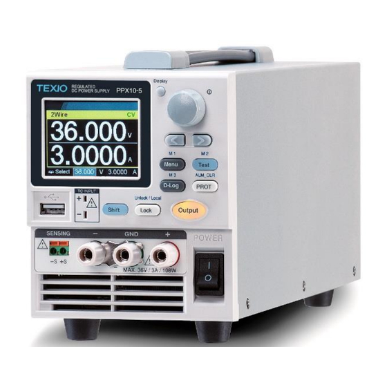
PPX Series Programming Manual Appearance Front Panel REGULATED PPX36-3 DC POWER SUPPLY 1. Display Used to switch among 4 different Button display modes. Used to navigate menu, and to 2. Knob Key configure or confirm voltage/current/time values, among others. Also, the indicator on the upper-right corner shows current state and power mode. - Page 12 PPX Series Programming Manual 3. Left/Right Used to select a parameter number in Arrow Keys the Function settings. Also the left arrow key can be used as backspace. 4. Menu Button Used to enter the Menu page. M1 Button (+Shift) Used to recall the M1 setup.
- Page 13 PPX Series Programming Manual 10. Output Used to turn the output on or off. Button USB A port for data transfer, loading 11. USB A Port test scripts and firmware update. 12. TC Input Terminal to connect the K type thermocouple cable for temperature measurement.
- Page 14 PPX Series Programming Manual DC output terminal for PPX is Binding Posts Terminal. PPX20-2 the max. output is 20V/2A/40W DC output terminal for PPX is Binding Posts Terminal. PPX20-5 the max. output is 20V/5A/100W DC output terminal for PPX is Binding Posts Terminal.
- Page 15 PPX Series Programming Manual Display Area 1. 2Wire/4Wire 2-wire or 4-wire indicator. 2. Voltage Meter Displays the voltage. 3. Current Meter Displays the current. 4. V/A Set The scrolling symbol indicates to select Guidance between V and A set via scrolling knob key.
- Page 16 Indicator is underway, the icon will be shown. 13. USB Indicator When USB disk is inserted into the front panel of PPX series, the icon will be shown. 14. External Output When external output enable is turned On, the Indicator icon will be shown.
- Page 17 PPX Series Programming Manual Rear Panel 1. Remote- RJ-45 connector that is used to daisy chain power supplies with the Remote-IN port to form a communication bus. 2. Remote-IN Two different types of cables can be used for RS- 232C or RS485-based remote control.
- Page 18 PPX Series Programming Manual 7. Line Voltage AC inlet. Input 8. AC Select The AC selector is located at the Switch bottom side of the unit. Switch Voltage to 100V, 120V, 220V or 240V.
-
Page 19: Theory Of Operation
PPX Series Programming Manual Theory of Operation The theory of operation chapter describes the basic principles of operation, protection modes and important considerations that must be taken into account before use. Operating Description Background The PPX power supplies are regulated DC power supplies with a stable voltage and current output. - Page 20 PPX Series Programming Manual CC and CV Mode CC and CV When the power supply is operating in constant mode current mode (CC) a constant current will be Description supplied to the load. When in constant current mode the voltage output can vary, whilst the current remains constant.
- Page 21 PPX Series Programming Manual Conversely the power supply will operate in CC mode when the load resistance is less than the critical resistance. In CC mode the current output is equal to I and the voltage output is less than V Crossover >R...
- Page 22 PPX Series Programming Manual Bleeder Control Background The PPX DC power supplies employ a Bleed circuit in parallel with the output terminals. Bleed Load circuit Bleed circuits are designed to dissipate the power from the power supply filter capacitors when power is turned off and the load is disconnected.
- Page 23 PPX Series Programming Manual Alarms The PPX power supplies have a number of protection features. When one of the protection alarms is set, the ALM icon on the display will be lit. Over voltage protection (OVP) prevents a high voltage from damaging the load. This alarm can be set by the user.
- Page 24 PPX Series Programming Manual Considerations The following situations should be taken into consideration when using the power supply. Inrush current When the power supply switch is first turned on, an inrush current is generated. Ensure there is enough power available for the power supply when first turned on, especially if a number of units are turned on at the same time.
- Page 25 PPX Series Programming Manual Reverse Current: When the power supply is connected to a Regenerative regenerative load such as a transformer or inverter, reverse current will feed back to the load power supply. The PPX power supply cannot absorb reverse current. For loads that create...
- Page 26 PPX Series Programming Manual Ensure the reverse withstand voltage of the CAUTION diode is able to withstand 2 times the rated output voltage of the power supply and the forward current capacity can withstand 3 to 10 times the rated output current of the power supply.
- Page 27 PPX Series Programming Manual Grounding The output terminals of the PPX power supplies are isolated with respect to the protective grounding terminal. The insulation capacity of the load, the load cables and other connected devices must be taken into consideration when connected to the protective ground or when floating.
- Page 28 PPX Series Programming Manual Grounded output If the positive or negative terminal is connected terminal to the protective ground terminal, the insulation capacity needed for the load and load cables is greatly reduced. The insulation capacity only needs to be greater than the maximum output voltage of the power supply with respect to ground.
-
Page 29: Remote Control
PPX Series Programming Manual REMOTE CONTROL This chapter describes basic configuration of IEEE488.2 based remote control Interface Configuration USB Remote Interface Configuration Type A, host PC side connector Configuration Rear panel Type B, slave PPX side connector 1.1 (full speed) - Page 30 PPX Series Programming Manual USB CDC Function Check Background To test the USB CDC functionality, National Instruments Measurement and Automation Explorer can be used. This program is available on the NI website, www.ni.com., via a search for the VISA Run-time Engine page, or “downloads”...
- Page 31 PPX Series Programming Manual The Device Manager will show up CDC-WXXXXXX on “Other Devices”. Select the CDC-WXXXXXX and click the right button of mouse to "Update Driver Software".
- Page 32 PPX Series Programming Manual Select "Locate and install driver software manually." Indicate the driver folder to the system and then press "Next". And this folder should consist of below 2 files. texio_cdc_*.inf , texio_cdc_*.cat The USB driver of PPX can be downloaded...
- Page 33 PPX Series Programming Manual Windows 7 will install the driver for a while. If everything works fine, you may get below message. And the COM53 is the USB CDC ACM port of PPX.
- Page 34 PPX Series Programming Manual Double check the "Device Manager". The port should like below. Steps 1~10 are for the USB CDC Driver installation. Start the NI Measurement and Automation Explorer (MAX) program. Using Windows, press: Start>All Programs>National Instruments>Measurement & Automation...
- Page 35 PPX Series Programming Manual From the Configuration panel access; My System>Devices and Interfaces>Network Devices Click Open VISA Test Panel. Click the Configuration icon, Click on I/O Settings. Make sure the Enable Termination Character check box is checked, and the terminal character is \n (Value: xA).
- Page 36 PPX Series Programming Manual The *IDN? query will return the Manufacturer, model name, serial number and firmware version in the dialog box. TEXIO,PPX36-3,TW123456,V0.A4 TEXIO、 PPX36-3、TW 123456、V0.A4...
- Page 37 PPX Series Programming Manual GP-IB Remote Interface Configuration GP-IB can be used with PPX series type G. Only one GP-IB address can be used at a time. Configure GP-IB 1. Ensure the PPX is off before proceeding. Connect the GP-IB cable (TEXIO part number: GTL-258) from a GP-IB controller to the GP-IB port on the PPX.
- Page 38 PPX Series Programming Manual GP-IB Function Check To test the GP-IB functionality, National Background Instruments Measurement and Automation Explorer can be used. Please download this program by searching for the NI-488.2 driver on the NI website at www.ni.com. Requirements Operating System: Windows 7 or higher.
- Page 39 PPX Series Programming Manual 4. Select the device (GP-IB address of PPX) that now appears in the System>Devices and Interfaces > GPIB-USB-HS “GPIBX” node. 5. Click on the VISA Properties tab on the bottom. 6. Click Open Visa Test Panel.
- Page 40 PPX Series Programming Manual 7. Click on Configuration. 8. Click on the GPIB Settings tab and confirm that the GP-IB settings are correct. 9. Click on the I/O Settings tab. 10. Make sure the Enable Termination Character check box is checked, and the terminal character is \n (Value: xA).
- Page 41 PPX Series Programming Manual 14. Enter *IDN? in the Select or Enter Command drop down box. 15. Click Query. 16. The *IDN? query will return the Manufacturer, model name, serial number and firmware version in the dialog box. TEXIO,PPX36-3,XXXXXXX,VX.XX TEXIO,PPX36-3,XXXXXXX,VX.XX...
- Page 42 PPX Series Programming Manual UART Remote Interface Configure UART Overview The PPX uses the IN & OUT ports for UART communication coupled with RS-232C (TEXIO part number: GTL-259) or RS-485 adapters (TEXIO part number: GTL-260). The pin outs for the adapters are shown below.
- Page 43 PPX Series Programming Manual RS-485 cable DB-9 Connector Remote IN Port Remarks with DB9 & RJ- Pin No. Name Pin No. Name 45 shielded Housing Shield Housing Shield connectors from GTL-260 TXD - RXD - Twisted connection kit pair TXD +...
- Page 44 Serial number, and Firmware version in the following format. TEXIO,PPX36-3,XXXXXXX,VX.XX Manufacturer: TEXIO Model number : PPX36-3 Serial number : XXXXXXX Firmware version : VX.XX For further details, please see the programming Note manual, available on the TEXIO web site.
- Page 45 PPX Series Programming Manual Multiple Connection The PPX power supplies can be daisy-chained up to 31 units using the 8-pin connector (input / output port) on the rear panel. The first device in the chain connects remotely to the PLC using USB / LAN / GP-IB or GTL-260 (RS-485 cable with DB9 connector).
- Page 46 PPX Series Programming Manual 4. Connect all theremaining units between the OUT port and the IN port with the slave serial link cable (black plug) supplied in the GTL-262 until all the desired units have been daisy- chained together. 5. Terminate the OUT port of the last unit with the end terminal connector included in the GTL- 261 connection kit.
- Page 47 PPX Series Programming Manual Click knob key to enter the Interface page followed by scroll knob key to move to UART field.
- Page 48 PPX Series Programming Manual Click knob key to enter the UART page. Scroll knob key to move to Mode field followed by clicking and scrolling knob key to select RS485. Click knob key to confirm selection. Scroll knob key to move to Address field followed...
- Page 49 PPX Series Programming Manual Steps of seting Press the Menu key followed by scrolling knob key the Multi-Drop to move to APP field. setting parameter to Slave for all slave units. Click knob key to enter the APP page followed by...
- Page 50 PPX Series Programming Manual Steps of setting Click knob key to enter the Multi-Drop page the Multi-Drop followed by scroll knob key to move to Mode field. Click knob key followed by scrolling knob setting to slave key to select Slave. Click knob key again to confirm setting.
- Page 51 PPX Series Programming Manual Steps of Press the Menu key followed by scrolling knob key checking the to move to APP field. slaves’ Click knob key to enter APP page followed by addresses by scrolling knob key to move to Multi-Drop field.
- Page 52 PPX Series Programming Manual Steps of setting Press the Menu key followed by scrolling knob key the Multi-Drop to move to APP field. setting Click knob key to enter APP page followed by parameter to scrolling knob key to move to Multi-Drop field.
- Page 53 PPX Series Programming Manual Steps of Press the Menu key followed by scrolling knob key displaying the to move to APP field. status of each Click knob key to enter APP page followed by slave unit by scrolling knob key to move to Multi-Drop field.
- Page 54 PPX Series Programming Manual Slave serial link RS-485 slave serial link pin assignment cable with RJ-45 8 Pin Connector (IN) 8 Pin Connector (OUT) shielded connectors from Pin No. Name Pin No. Name GTL-262 Housing Shield Housing Shield connection kit...
- Page 55 PPX Series Programming Manual Multi-Unit Connection 1. Connect the first unit's IN port to a PLC using PLC Operation RS-485 cable with DB9 & RJ-45. 2. Turn on the Terminator Unit #1 RS 485 / 232 To PLC on the PLC side.
- Page 56 PPX Series Programming Manual 7. Multiple units can be operated using SCPI commands now. See the programming manual or see the function check below for usage details. RS232 cable DB-9 Connector Remote-IN Port Remarks with DB9 & RJ- Pin No.
- Page 57 PPX Series Programming Manual Multiple units Function Check Functionality Invoke a terminal application such as Realterm. check To check the COM port No, see the Device Manager in the PC. For this function check, we will assume that the one unit is assigned to address 0, while other is assigned address 5.
- Page 58 The PPX series supports both DHCP connections so the instrument can be automatically connected to an existing network or alternatively, network settings can be manually configured.
- Page 59 PPX Series Programming Manual Turn On DHCP and Web Server settings. The indicator will be shown when a remote connection has been established. It may be necessary to cycle the power or Note refresh the web browser to connect to a...
- Page 60 PPX Series Programming Manual Web Server Remote Control Function Check Functionality Enter the IP address of the power supply in a check web browser after the instrument has been configured as a web server. The web server allows you to monitor the function settings of the PPX.
- Page 61 PPX Series Programming Manual The web browser interface allows you to access the following: Network configuration settings Measurement setting Normal Function setting...
- Page 62 PPX Series Programming Manual External Control setting Temperature Control setting Analog Control It is instruction manual. Figure of Dimension It is an external dimension. Sequence setting...
- Page 63 PPX Series Programming Manual Datalog setting...
- Page 64 PPX Series Programming Manual Sockets Server Configuration This configuration example will configure the Configuration PPX socket server. The following configuration settings will manually assign the PPX an IP address and enable the socket server. The socket server port number is fixed at 2268.
- Page 65 PPX Series Programming Manual Socket Server Function Check To test the socket server functionality, National Background Instruments Measurement and Automation Explorer can be used. This program is available on the NI website, www.ni.com., via a search for the VISA Run-time Engine page, or “downloads”...
- Page 66 PPX Series Programming Manual Select Manual Entry of Raw Socket from the popup window. Enter the IP address and the port number of the PPX. The port number is fixed at 2268. Click the Validate button. A popup will appear if a connection is successfully established.
- Page 67 PPX Series Programming Manual Next configure the Alias (name) of the PPX connection. In this example the Alias is: PPX_DC1 Click finish. The IP address of the PPX will now appear under Network Devices in the configuration panel. Select this icon now.
- Page 68 PPX Series Programming Manual Click the Configuration icon, Click on I/O Settings. Make sure the Enable Termination Character check box is checked, and the terminal character is \n (Value: xA). Click Apply Changes. Click the Input/Output icon. Enter *IDN? in the Select or Enter Command dialog box if it is not already.
- Page 69 PPX Series Programming Manual TEXIO,PPX36-3,XXXXXXXX,VX.XX TEXIO、PPX36-3、XXXXXXX、VX.XX...
-
Page 70: Command Syntax
PPX Series Programming Manual Command Syntax Compatible IEEE488.2 Partial compatibility Standard SCPI, 1999 Partial compatibility Command SCPI commands follow a tree-like structure, Structure organized into nodes. Each level of the command tree is a node. Each keyword in a SCPI command represents each node in the command tree. - Page 71 PPX Series Programming Manual command must begin at the last node of the first command. A semi-colon and colon are used to combine two commands from different nodes. Example meas:volt:dc?;:meas:curr:dc? Command Commands and queries have two different Forms forms, long and short. The command syntax is...
- Page 72 PPX Series Programming Manual Parameters Type Description Example <Boolean> Boolean logic 0, 1 <NR1> integers 0, 1, 2, 3 <NR2> decimal 0.1, 3.14, 8.5 numbers <NR3> floating point 4.5e-1, 8.25e+1 <NRf> any of NR1, 2, 3 1, 1.5, 4.5e-1 <block data> Definitive length arbitrary block data.
-
Page 73: Command List
PPX Series Programming Manual Command List Abort Command :ABORt ..............76 Apply Commands :APPLy ..............76 Address Commands :ADR ............... 77 Initiate Commands :INITiate:CONTinuous[:TRANsient] ......77 :INITiate[:IMMediate]:NAME ........78 :INITiate[:IMMediate][:TRANsient] ......78 Memory Commands :MEMory:TRIGgered ..........78 Measure Commands :MEASure[:SCALar]:ALL[:DC] ......... 83 :MEASure[:SCALar]:CURRent[:DC] ...... - Page 74 PPX Series Programming Manual :STATus:OPERation:NTRansition ......91 :STATus:QUEStionable[:EVENt] ......91 :STATus:QUEStionable:CONDition ......91 :STATus:QUEStionable:ENABle ......92 :STATus:QUEStionable:PTRansition ....... 92 :STATus:QUEStionable:NTRansition ...... 92 :STATus:PRESet ............ 93 Source Commands [:SOURce]:CURRent[:LEVel][:IMMediate][:AMPLitude] ................93 [:SOURce]:CURRent[:LEVel]:TRIGgered[:AMPLitude] ................94 [:SOURce]:CURRent:LIMit:AUTO......94 [:SOURce]:CURRent:PROTection:DELay ....95 [:SOURce]:CURRent:PROTection[:LEVel] ....95 [:SOURce]:CURRent:PROTection:TRIPped ....
- Page 75 PPX Series Programming Manual :SYSTem:COMMunicate:ENABle ......112 :SYSTem:COMMunicate:GP-IB[:SELF]:ADDRess ... 113 :SYSTem:COMMunicate:LAN:IPADdress ....113 :SYSTem:COMMunicate:LAN:GATEway ....113 :SYSTem:COMMunicate:LAN:SMASk ..... 114 :SYSTem:COMMunicate:LAN:MAC ......114 :SYSTem:COMMunicate:LAN:DHCP ....... 114 :SYSTem:COMMunicate:LAN:DNS ......115 :SYSTem:COMMunicate:RLSTate ......115 :SYSTem:COMMunicate:TCPip:CONTrol ....115 :SYSTem:COMMunicate:SERial[:RECeive] :TRANsmit:B AUD ................ 116 :SYSTem:COMMunicate:SERial[:RECeive] :TRANsmit:B ITS ................
-
Page 76: Abort Command
PPX Series Programming Manual Abort Command :ABORt Description The :ABORt command will cancel any triggered actions. Syntax :ABORt Apply Commands :APPLy Query Description The apply command sets the voltage and current at the same time. Syntax :APPLy {<NRf>(V)|MINimum|MAXimum[,<NRf>(A)|MINimu m|MAXimum]} Query Syntax :APPLy? Voltage setting. -
Page 77: Address Commands
PPX Series Programming Manual Address Commands :ADR Query Description Sets or queries the RS-485 interface address. Syntax :ADR <NR1> Query Syntax :ADR? Parameter/ <NR1> 0~30 Return parameter Example ADR 5 Sets the RS485 address 5. Initiate Commands :INITiate:CONTinuous[:TRANsient] ....77 :INITiate[:IMMediate]:NAME ...... -
Page 78: Initiate[:Immediate]:Name
PPX Series Programming Manual :INITiate[:IMMediate]:NAME Description The INITiate command starts the TRANsient or OUTPut trigger. Syntax :INITiate[:IMMediate]:NAME {TRANsient|OUTPut} Starts the TRANsient trigger. Parameter TRANSient OUTPut Starts the OUTPut trigger. Example INITiate:NAME TRANient Starts the TRANSient trigger. :INITiate[:IMMediate][:TRANsient] Description This command controls the enabling of output triggers. - Page 79 PPX Series Programming Manual Syntax :MEMory:TRIGgered{<NR1>|MINimum|MAXimum Query Syntax :MEMory:TRIGgered? [MINimum|MAXimum] 0(M1)~9(M10). Parameter <NR1> MINimum MAXimum Returns the memory setting. Return <NR1> parameter Instrument Commands :INSTrument:SCAN Query Description Links the units which could be scanned from system when using Multi-Drop mode.
- Page 80 PPX Series Programming Manual :INSTrument:STATe Query Description Displays the status (on-line/off-line) of each slave unit and the address of master unit, when using the Multi-Drop mode. Query Syntax :INSTrument:STATe? 4. 0~2147483647, 0~30 Return <NR1>,<NR1> parameter (2147483647=2^31-1) 5. First value: 6. Each bit of the binary value corresponds to a unit from 0 to 30 (LSB to MSB).
- Page 81 PPX Series Programming Manual System Commands :SYSTem:COMMunicate:MULTidrop :CONTrol Query Description Queries the Multi-Drop Control state. Query Syntax SYST:COMM:MULT:CONT? Return <NR1>Disable parameter <NR1>Master <NR1>Slave :SYSTem:CAPacity:AHOur Query Description Sets or queries the Ampere-hour capacity. This is the equivalent to the Ah/Wh Meter menu (AHour) settings.
- Page 82 PPX Series Programming Manual Syntax :SYSTem:CAPacity:WHOur {<NR2>|MINimum|MAXimum} Query Syntax :SYSTem:CAPacity:WHOur? [MINimum|MAXimum] Parameter <NR2> 0.001~999999999.999 MINimum 0.001 MAXimum 999999999.999 Return <NR2> Returns the Watt-hour capacity. Parameter :SYSTem:CAPacity:MODE Query Description Sets or queries the capacity mode. This is the equivalent to the AH/WH Meter menu (Mode) settings.
-
Page 83: Measure Commands
PPX Series Programming Manual AHour/Whour capacity isn’t reached. Parameter AHour/Whour capacity is reached. Return <NR1> Returns the capacity state. Parameter Measure Commands :MEASure[:SCALar]:ALL[:DC] Query Description Takes a measurement and returns the average output current and voltage Syntax :MEASure[:SCALar]:ALL[:DC]? Return "+0.0000,+0.00000,+0.0 <voltage>,<current>... -
Page 84: Measure[:Scalar]:Power[:Dc]
PPX Series Programming Manual :MEASure[:SCALar]:POWer[:DC] Query Description Takes a measurement and returns the average output power. Syntax :MEASure[:SCALar]:POWer[:DC]? Returns the power measured in watts. Return "+0.0000" :MEASure[:SCALar]:CURRent:RANGe Query Description Sets or queries the current measurement range. Syntax :MEASure[:SCALar]:CURRent:RANGe {<NR1>|AUTO|IH|IL|ILL} Query Syntax... -
Page 85: Output Commands
PPX Series Programming Manual Syntax :MEASure:TEMPerature? “+0.0000” Returns the temperature in celsius or Return Return fahrenheit. -32768 Returns the temperature in INVAILD. Output Commands :OUTPut:DELay:ON Query Description Sets the Delay Time in seconds for turning the output on. The delay is set to 0.00 by default. -
Page 86: Output[:State][:Immediate]
PPX Series Programming Manual CV high speed priority Parameter CVHS | 0 CC high speed priority CCHS | 1 CVLS | 2 CV slew rate priority CCLS | 3 CC slew rate priority Returns the output mode. Return <NR1> parameter... -
Page 87: Output:protection:tripped
PPX Series Programming Manual Syntax :OUTPut:PROTection:CLEar :OUTPut:PROTection:TRIPped Query Description Queries the unit to see if a protection circuit has been tripped. Syntax :OUTPut:PROTection:TRIPped? Return <boolean> 0 = No protection error 1 = A protection error had occured :OUTPut:PROTection:WDOG[:STATe] Query Description Enables or disables the communication monitor setting. -
Page 88: Sense Commands
PPX Series Programming Manual Sense Commands :SENSe:AVERage:COUNt Query Description Sets or queries the level of smoothing for the average setting. Syntax :SENSe:AVERage:COUNt {<NR1>|LOW|MIDDle|HIGH} :SENSe:AVERage:COUNt? Return Syntax Default setting Parameter OFF | 0 Low setting LOW | 0 MIDDle | 1... -
Page 89: Sense:dlog:period
PPX Series Programming Manual Disable data logger. Parameter Enable data logger.The data is stored in the USB storage when USB storage plug Enable data logger, The log data is saving in the PPX. Return <NR1> Returns the data logger setting. -
Page 90: Status Commands
PPX Series Programming Manual Status Commands For an overview of all the status registers, their associated register contents and the system diagram, please see the status overview on page 131 :STATus:OPERation[:EVENt] Query Description Queries the Operation Status Event register and clears the contents of the register. -
Page 91: Status:operation:ntransition
PPX Series Programming Manual Syntax :STATus:OPERation:PTRansition <NR1> Query Syntax :STATus:OPERation:PTRansition? 0~32767 Parameter <NR1> Return <NR1> 0~32767 parameter :STATus:OPERation:NTRansition Query Description Sets or queries the bit sum of the negative transition filter of the Operation Status register. Syntax :STATus:OPERation:NTRansition <NR1> Query Syntax... -
Page 92: Status:questionable:enable
PPX Series Programming Manual :STATus:QUEStionable:ENABle Query Description Sets or queries the bit sum of the Questionable Status Enable register. Syntax :STATus:QUEStionable:ENABle <NR1> Query Syntax :STATus:QUEStionable:ENABle? Parameter <NR1> 0~32767 Return <NR1> 0~32767 parameter :STATus:QUEStionable:PTRansition Query Description Sets or queries the bit sum of the positive transition filter of the Questionable Status register. -
Page 93: Status:preset
PPX Series Programming Manual :STATus:PRESet Description This command resets the ENABle register, the PTRansistion filter and NTRansistion filter on the Operation Status and Questionable Status Registers. The registers/filters will be reset to a default value. Default Register/Filter Values Setting QUEStionable Status Enable... -
Page 94: [:Source]:Current[:Level]:Triggered[:Amplitude]
PPX Series Programming Manual Example SOUR:CURR:LEV:IMM:AMPL? +1.0000 Returns the current level in amps. [:SOURce]:CURRent[:LEVel]:TRIGgered [:AMPLitude] Query Description Sets or queries the current level in amps when a software trigger has been generated. Syntax [:SOURce]:CURRent[:LEVel]:TRIGgered[:AMPLitu de] {<NR2> (A)| MINimum|MAXimum} Query Syntax... -
Page 95: [:Source]:Current:protection:delay
PPX Series Programming Manual [:SOURce]:CURRent:PROTection:DELay Query Description Sets the Delay Time for OCP in seconds. The delay is set to 0.05 by default. Syntax [:SOURce]:CURRent:PROTection:DELay {<NR2>|MINimum|MAXimum} Query Syntax [:SOURce]:CURRent:PROTection:DELay? Parameter <NR2> 0.05~2.5 seconds The maximum allowed delay time The minimum allowed delay time... -
Page 96: [:Source]:Current:protection:tripped
PPX Series Programming Manual [:SOURce]:CURRent:PROTection:TRIPped Query Description Returns the state of the current protection circuits. Query Syntax [:SOURce]:CURRent:PROTection:TRIPped? Returns protection status. Return <bool> parameter Example SOUR:CURR:PROT:TRIP? >0 The protection circuit has not been tripped. [:SOURce]:CURRent:SLEWrate:RISing Query Description Sets or queries the rising current slew rate. This is only applicable for CC slew rate priority (CCLS) mode. -
Page 97: [:Source]:Current:slewrate:falling
PPX Series Programming Manual [:SOURce]:CURRent:SLEWrate:FALLing Query Description Sets or queries the falling current slew rate. This is only applicable for CC slew rate priority (CCLS) mode. Syntax [:SOURce]:CURRent:SLEWrate:FALLing {<NR2>(A)|MINimum|MAXimum} Query Syntax [:SOURce]:CURRent:SLEWrate:FALLing? Parameter <NR2> Per step is between 0.00001A/msec and depend on the unit type: 0.01 /0.02 /0.03 /0.05... -
Page 98: [:Source]:Voltage[:Level][:Immediate][:Amplitude]
PPX Series Programming Manual [:SOURce]:VOLTage[:LEVel][:IMMediate ][:AMPLitude] Query Description Sets or queries the voltage level in volts. Syntax [:SOURce]:VOLTage[:LEVel][:IMMediate][:AMPLitu de] {<NR2>(V)|MINimum|MAXimum} Query Syntax [:SOURce]:VOLTage[:LEVel][:IMMediate][:AMPLitu de]? 0~105% of the rated output voltage in volts. Parameter <NRf> Minimum voltage level Maximum voltage level... -
Page 99: [:Source]:Voltage:limit:auto
PPX Series Programming Manual [:SOURce]:VOLTage:LIMit:AUTO Query Description Sets whether to limit the voltage setting so that it does not exceed the OVP setting or become lower than the UVL setting. If you enable the limit when the OVP setting is lower than the voltage setting, the OVP setting will be set to 105 % of the voltage setting. -
Page 100: [:Source]:Voltage:protection[:Level]
PPX Series Programming Manual [:SOURce]:VOLTage:PROTection[:LEVe Query Description Sets or queries the overvoltage protection level. Syntax [:SOURce]:VOLTage:PROTection[:LEVel] {<NR2>(V)|MINimum|MAXimum} Query Syntax [:SOURce]:VOLTage:PROTection[:LEVel]? Parameter/Retur <NR2> Minimum: Vrated * 0.05 Maximum: Vrated * 1.1 Minimum OVP level Maximum OVP level Example SOUR:VOLT:PROT:LEV MAX Sets the OVP level to its maximum. -
Page 101: [:Source]:Voltage:slewrate:rising
PPX Series Programming Manual [:SOURce]:VOLTage:SLEWrate:RISing Query Description Sets or queries the rising voltage slew rate. This is only applicable for CV slew rate priority (CVLS) mode. Syntax [:SOURce]:VOLTage:SLEWrate:RISing {<NR2>(V)|MINimum|MAXimum} Query Syntax [:SOURce]:VOLTage:SLEWrate:RISing? Parameter <NR2> Per step is between 0.0001V/msec and depend on the unit type: 0.1 /0.2 /0.36 /1... -
Page 102: [:Source]:Voltage:sense
PPX Series Programming Manual [:SOURce]:VOLTage:SENSe Query Description Sets or queries the remote sense. Syntax [:SOURce]:VOLTage:SENSe {<NR1>|INTernal|EXTernal} Query Syntax [:SOURce]:VOLTage:SENSe? Parameter <NR2> Sets remote sense 2 wire INTernal | Sets remote sense 4 wire EXTernal | Return <NR1> parameter Example SOUR:VOLT: SENS EXT Sets remote sense 4 wire. -
Page 103: [:Source]:Power:control
PPX Series Programming Manual [:SOURce]:POWer:CONTrol Query Description Enables or disables the constant power setting. Syntax [:SOURce]:POWer:CONTrol {<bool>|OFF|ON} Query Syntax [:SOURce]:POWer:CONTrol? Parameter OFF | 0 Disable the constant power control. Enable the constant power control. ON | 1 Returns the setting in <bool> format. -
Page 104: System:configure:beeper[:State]
PPX Series Programming Manual Example 1 :SYST:BEEP 10 **after a 2 second wait** :SYST:BEEP? >8 The first command turns the beeper on for 10 seconds. After 2 seconds the SYST:BEEP? query returns the remaining beeper time (8 seconds). Example 2 :SYST:BEEP? MAX >3600... -
Page 105: System:configure:current:control
PPX Series Programming Manual :SYSTem:CONFigure:CURRent:CONTro Query Description Sets or queries the CC control mode (local control (panel), external voltage control, external resistance control). Note: It can not be set when output on. Syntax :SYSTem:CONFigure:CURRent:CONTrol { <NR1>|NONE|VOLTage|RRISing } Query Syntax :SYSTem:CONFigure:CURRent:CONTrol? Parameter <NR1>... -
Page 106: System:configure:output:pon[:State]
PPX Series Programming Manual :SYSTem:CONFigure:OUTPut:PON[:ST ATe] Query Description Sets the output state at power-on. This is the equivalent to the PWR On Config menu(Power On Status) settings. These settings only apply after the unit has been reset. Syntax :SYSTem:CONFigure:OUTPut:PON[:STATe] {<NR1>|{SAFE|OFF}|{FORCe|ON}|AUTO}... -
Page 107: System:configure:output:external[:State]
PPX Series Programming Manual :SYSTem:CONFigure:OUTPut:EXTernal[:ST ATe] Query Description Sets the output on or off when using an external contact. This is the equivalent to the EXT Control menu(Output Enable)settings. Syntax :SYSTem:CONFigure:OUTPut:EXTernal[:STATe] {<bool>|OFF|ON} Query Syntax :SYSTem:CONFigure:OUTPut:EXTernal[:STATe]? Parameter OFF | 0 External output control disable. -
Page 108: System:configure:trigger:input:level
PPX Series Programming Manual :SYSTem:CONFigure:TRIGger:INPut:LE Query Description Sets or queries the logic used to input trigger level. This is the equivalent to the TRIG Control menu (Trigin Level)settings. Syntax :SYSTem:CONFigure:TRIGger:INPut:LEVel {<NR1>|LOW|HIGH} Query Syntax :SYSTem:CONFigure:TRIGger:INPut:LEVel? Parameter LOW | 0 Active high. -
Page 109: System:configure:trigger:output:width
PPX Series Programming Manual :SYSTem:CONFigure:TRIGger:OUTPut:WI Query Description Sets or queries the output trigger pulse width. This is the equivalent to the TRIG Control menu(Trigout Width)settings. Syntax :SYSTem:CONFigure:TRIGger:OUTPut:WIDTh {<NR2>|MINimum|MAXimum} Query Syntax :SYSTem:CONFigure:TRIGger:OUTPut:WIDTh? [MINimum|MAXimum] Parameter <NR2> 1.0 ~100.0 unit:ms. MINimum 1.0 unit:ms Maximum 100.0 unit:ms... -
Page 110: System:configure:temperature:unit
PPX Series Programming Manual Description Sets or queries the temperature control (K-Type Thermocouple) on/off. This is the equivalent to the Temperature menu (Control)settings. Syntax :SYSTem:CONFigure:TEMPerature:CONTrol {<bool>|OFF|ON} Query Syntax :SYSTem:CONFigure:TEMPerature:CONTrol? Parameter OFF | 0 Turns the temperature control off. ON | 1 Turns the temperature control on. -
Page 111: System:configure:temperature:monitor
PPX Series Programming Manual Sets the temperature output safe off. Parameter OFF | 0 ON | 1 Sets the temperature output safe on. Returns the temperature output safe status. Return <bool> Parameter :SYSTem:CONFigure:TEMPerature:MONi Query Description Sets or queries the monitored temperature. This is the equivalent to the Temperature menu (Monitor)settings. -
Page 112: System:communicate:enable
PPX Series Programming Manual Parameter <NR2> MINimum -2.5(Celsius) / -4.5(Fahrenheit) 2.5(Celsius) / 4.5(Fahrenheit) MAXimum Return <NR1> Returns the adjust temperature. Parameter :SYSTem:COMMunicate:ENABle Query Description Enables/Disables GP-IB, USB or other remote interfaces such as Sockets and the Web Server. This setting is only applied after the unit has been reset. -
Page 113: System:communicate:gp-Ib[:Self]:Address
PPX Series Programming Manual :SYSTem:COMMunicate:GP-IB[:SELF] :ADDRess Query Description Sets or queries the GP-IB address. Note: the setting will only be valid after the power has been cycled. Syntax :SYSTem:COMMunicate:GP-IB[:SELF]:ADDRess <NR1> Query Syntax :SYSTem:COMMunicate:GP-IB[:SELF]:ADDRess? Parameter/Retur <NR1> 0~30 Example SYST:COMM:GP-IB:SELF:ADDR 15 Sets the GP-IB address to 15. -
Page 114: System:communicate:lan:smask
PPX Series Programming Manual :SYSTem:COMMunicate:LAN:SMASk Query Description Sets or queries the LAN subnet mask. Note: the setting will only be valid after the power has been cycled. Syntax :SYSTem:COMMunicate:LAN:SMASk <string> Query Syntax :SYSTem:COMMunicate:LAN:SMASk? Subnet mask in string format ( “mask”) Parameter/Retur <string>... -
Page 115: System:communicate:lan:dns
PPX Series Programming Manual :SYSTem:COMMunicate:LAN:DNS Query Description Sets or queries the DNS address. Note: the setting will only be valid after the power has been cycled. Syntax :SYSTem:COMMunicate:LAN:DNS <string> Query Syntax :SYSTem:COMMunicate:LAN:DNS? DNS in string format ( “mask”) Parameter/Retur <string>... -
Page 116: System:communicate:serial[:Receive] :Transmit:baud
PPX Series Programming Manual :SYSTem:COMMunicate:SERial[:RECeiv :TRANsmit:BAUD Query Description Sets or queries the UART baud rate. Note: the setting will only be valid after the power has been cycled. Syntax :SYSTem:COMMunicate:SERial[:RECeive]:TRANs :BAUD <NR1> Query Syntax :SYSTem:COMMunicate:SERial[:RECeive]:TRANs :BAUD? Parameter/Retur <NR1> 2400, 4800, 9600, 19200, 38400, 57600,... -
Page 117: System:communicate:serial[:Receive] :Transmit:parity
PPX Series Programming Manual Example SYST:COMM:SER:TRAN:BITS? >1 Indicates that 8 data bits are used for the UART connection. :SYSTem:COMMunicate:SERial[:RECeiv :TRANsmit:PARity Query Description Sets or queries the parity of the UART connection. Note: the setting will only be valid after the power has been cycled. -
Page 118: System:communicate:usb:front:state
PPX Series Programming Manual 2 stop bits n parameter Example SYST:COMM:SER:TRAN:SBITs? >1 Indicates that one stop bit is used for the UART connection. :SYSTem:COMMunicate:USB:FRONt:ST Query Description Queries the front panel USB-A port state. Query Syntax :SYSTem:COMMunicate:USB:FRONt:STATe? Return <NR1>Absent parameter <NR1>Mass Storage... -
Page 119: System:keylock:mode
PPX Series Programming Manual Description Enables or disables the front panel key lock. Syntax :SYSTem:KLOCk {<bool>|OFF|ON } Query Syntax :SYSTem:KLOCk? Parameter OFF | 0 Panel keys unlocked ON | 1 Panel keys locked Returns the key lock status. Return <bool>... -
Page 120: System:keyboard:beeper
PPX Series Programming Manual Query Example SYST:VERS? >1999.9 :SYSTem:KEYBoard:BEEPer Query Description Sets or queries the keyboard buzzer state on/off. This is the equivalent to the Buzzer menu (Keyboard)settings. Syntax :SYSTem:KEYBoard:BEEPer {<bool>|OFF|ON} Query Syntax :SYSTem:KEYBoard:BEEPer? Parameter OFF | 0 Turns the keyboard buzzer off. -
Page 121: System:capacity:mode
PPX Series Programming Manual 0.001~999999999.999 Parameter <NR2> MINimum 0.001 999999999.999 MAXimum Return <NR2> Returns the Watt-hour capacity. Parameter :SYSTem:CAPacity:MODE Query Description Sets or queries the capacity mode. This is the equivalent to the AH/WH Meter menu (Mode) settings. Note: Install the license first. -
Page 122: System:capacity:state
PPX Series Programming Manual :SYSTem:CAPacity:STATe Query Description Queries the capacity state. Monitor the capacity when the output is turned on.Turn off the output when the monitored AHour/Whour capacity is reached. Note:The capacity mode is selected Ahour/Whour first. Query Syntax :SYSTem:CAPacity:STATe? AHour/Whour capacity isn’t reached. -
Page 123: Fetch:dlog
PPX Series Programming Manual :FETCh:DLOG? Query Description Queries the measurement of Watt-hour capacity. Note: Install the license first. The maximum number of data that can be returned Note at one time when logging is started is 1000. If the data is accumulated in the main body, issue the command again to acquire the data. - Page 124 PPX Series Programming Manual <sample period> 4 Logging interval unit is mS Set logging interval <number of Number of data in {Cell-N} data> {Cell-N} Returns the measurement data in the order of status, voltage, current. <end_code> Returns LF as the exit code after the byte data.
-
Page 125: Trigger Commands
PPX Series Programming Manual bit 13 (unused) bit 29 Sense alarm bit 14 TEST Mode bit 30 (unused) bit 15 (unused) bit 31 (unused) Query example FETC:DLOG? > #800000246***********************************<LF> Returns log data. The * part of the response example is the binary data part, which is 246 bytes. -
Page 126: Trigger[:Transient][:Immediate]
PPX Series Programming Manual Syntax :TRIGger[:TRANsient]:SOURce {BUS|IMMediate|EXTernal} Query Syntax :TRIGger[:TRANsient]:SOURce? Parameter/ Transient trigger is generated by the bus. Transient trigger is immediately generated. Return IMMediate parameter EXTernal The transient trigger is generated when an external signal triggers it. Example :TRIG:SOUR? Sets the transient trigger source to EXT. - Page 127 PPX Series Programming Manual TRIG:TRAN (or *TRG) <==The current changes to the maximum, and the voltage changes to 5V. 3. The output system for the trigger in immediate mode. Example 3 TRIG:OUTP:SOUR IMM OUTP:TRIG 1 INIT:NAME OUTP <==The output changes to ON.
- Page 128 PPX Series Programming Manual *ESR Query Description Queries the Standard Event Status (Event) register. The Event Status register is cleared after it is read. Query Syntax *ESR? Returns the bit sum of the Standard Event Return <NR1> Status (Event) register and clears the register.
- Page 129 PPX Series Programming Manual *RCL Description Recalls the contents stored in memory slot M1 ~ M10. Syntax *RCL {<NR1>|MAX|MIN} 0 ~ 9 (as memory M1 ~ M10) Parameter <NR1> Recalls the M1 memory contents. Recalls the M10 memory contents. *RST Description Performs a device reset.
-
Page 130: Wai
PPX Series Programming Manual *STB Query Description Queries the bit sum of the Status Byte register with MSS (Master summary Status) replacing the RQS bit (bit 6). Query Syntax *STB? Return <NR1> Returns the bit sum of the Status Byte register with the MSS bit (bit 6). -
Page 131: Status Register Overview
The status registers are used to determine the status of the power supply. The status registers maintain the status of the protection conditions, operation conditions and instrument errors. The PPX Series have a number of register groups: Questionable Status Register Group Standard Event Status Register Group... - Page 132 PPX Series Programming Manual The Status Registers Questionable Status Register Condition PTR/NTR Event Enable OV (Over-Voltage) OC (Over-Current) Not Used POW (AC Power Off) OT (Over-Temperature) Not Used Not Used Not Used VL (Voltage-Limit) CL (Current-Limit) Not Used SD (Shutdown Alarm)
- Page 133 PPX Series Programming Manual Questionable Status Register Group Overview The Questionable Status Register Group indicates if any protection modes or limits have been tripped. Questionable Status Register Condition PTR/NTR Event Enable & & & Not Used & & & Not Used &...
- Page 134 PPX Series Programming Manual TM(Temperature Monitor) Temperature monitor reached. VL (Voltage Limit) Voltage limit has been reached CL (Current Limit) Current limit has been reached SD (Shutdown Alarm) 2048 PL (Power-Limit) 4096 SA (Sense Alarm) 8192 Condition The Questionable Status Condition Register Register indicates the status of the power supply.
- Page 135 PPX Series Programming Manual Operation Status Register Group Overview The Operation Status Register Group indicates the operating status of the power supply. Operation Status Register Condition PTR/NTR Even Enable & & Not Used & Not Used & Not Used &...
- Page 136 PPX Series Programming Manual CP (Constant power mode) Indicates if the PPX is in CP mode. CC (Constant current mode) 1024 Indicates if the PPX is in CC mode. OND (Output ON Delay) 2048 Indicates if Output ON delay time is active...
- Page 137 PPX Series Programming Manual Standard Event Status Register Group Overview The Standard Event Status Register Group indicates if any errors have occurred. The bits of the Event register are set by the error event queue. Standard Event Status Register Event Enable &...
- Page 138 PPX Series Programming Manual DDE (Device Dependent Error) Device specific error. EXE (Execution Error) The EXE bit indicates an execution error due to one of the following: illegal command parameter, parameter out of range, invalid parameter, the command didn’t execute due to an overriding operation condition.
- Page 139 PPX Series Programming Manual Status Byte Register & Service Request Enable Register Overview The Status Byte register consolidates the status events of all the status registers. The Status Byte register can be read with the *STB? query and can be cleared with the *CLS command.
- Page 140 PPX Series Programming Manual MSS Bit The MSS Bit is the summary of the Status Byte Register and Service Request register (bits 1-5, 7). This will be set to 1. OPER (Operation Status Register) OPER bit is the summary bit for the Operation Status Register Group.
-
Page 141: Error List
PPX Series Programming Manual Error List Command Errors Overview An <error/event number> in the range [ -199 , - 100 ] indicates that an IEEE 488.2 syntax error has been detected by the instrument’s parser. The occurrence of any error in this class shall cause the command error bit (bit 5) in the event status register (IEEE 488.2, section 11.5.1) to... - Page 142 PPX Series Programming Manual Error Code Description -100 Command This is the generic syntax error for devices that Error cannot detect more specific errors. This code indicates only that a Command Error as defined in IEEE 488.2,11.5.1.1.4 has occurred. -102 Syntax...
- Page 143 PPX Series Programming Manual -115 The number of parameters received does not Unexpected correspond to the number of parameters number of expected. This is typically due an inconsistency parameters with the number of instruments in the selected group. -120 Numeric...
- Page 144 PPX Series Programming Manual -168 Block data A legal block data element was encountered but not allowed was not allowed by the device at this point in parsing. -178 Expression A legal expression data was encountered but data not allowed was not allowed by the device at this point in parsing.
- Page 145 PPX Series Programming Manual -201 Invalid Indicates that a command is not executable while in local while the device is in local due to a hard local control (see IEEE 488.2, 5.6.1.5); for example, a device with a rotary switch receives a...
- Page 146 PPX Series Programming Manual -224 Illegal Used where exact value, from a list of parameter value possibles, was expected. Device Specific Errors Overview An <error/event number> in the range [ -399 , - 300 ] or [ 1 , 32767 ] indicates that the...
- Page 147 PPX Series Programming Manual -320 Storage Indicates that the firmware detected a fault fault when using data storage. This error is not an indication of physical damage or failure of any mass storage element. Query Errors An <error/event number> in the range [ -499 , -...
-
Page 148: Ppx Series Default Settings
PPX Series Programming Manual PPX Series Default Settings The following default settings are the factory configuration settings for the power supply. Initial Default Setting Output LOCK Disabled Voltage Set 0.000 V Current Set 0.0000 A Output Output On Dly(Delay) 00(hour):00(minute):00.00(sec) Output Off Dly(Delay) 00(hour):00(minute):00.00(sec) - Page 149 PPX Series Programming Manual Constant PWR(Power) Control Power (1.05 X Vrate) * (1.05 X Irate) Temperature Control ℃ Unit Output Safe Monitor 100.0 ℃ Adjust ℃ Save/Recall Save Mem(Memory) Set Recall Mem(Memory) Set Utility - Buzzer Protect Keyboard Utility - Bleeder...
- Page 150 7F Towa Fudosan Shin Yokohama Bldg. 2-18-13, Shin Yokohama, Kohoku-ku,Yokohama, Kanagawa, 222-0033 Japan https://www.texio.co.jp/...
Need help?
Do you have a question about the PPX Series and is the answer not in the manual?
Questions and answers