Table of Contents
Advertisement
Quick Links
Download this manual
See also:
Programming Manual
Advertisement
Table of Contents

Related Manuals for TEXIO PFR-100M250


Summary of Contents for TEXIO PFR-100M250
- Page 1 INSTRUCTION MANUAL WIDE RANGE DC POWER SUPPLY PFR-100 SERIES PFR-100L50 PFR-100M250 PFR-100L50G PFR-100M250G B71-0479-01...
- Page 2 ■ About Brands and Trademarks “TEXIO” is the product brand name of our industrial electronic devices. All company names and product names mentioned in this manual are the trademark or the registered trademark of each company or group in each country and region.
-
Page 3: Table Of Contents
CONTENTS USING THE PRODUCT SAFELY ··························· Ⅰ-Ⅳ 1. GETTING STARTED ........... 1 1-1. PFR-100 Series Overview ..........1 1-1-1. Series lineup ..................1 1-1-2. Main Features ................... 1 1-1-3. Accessories ..................2 1-2. Appearance ..............3 1-2-1. Front Panel ..................3 1-2-2. - Page 4 2-3-9. Data structure of the Test Script ............37 2-3-10. Setting values of the test Script ............. 38 3. CONFIGURATION ............. 40 3-1. Configuration Table ............40 3-2. Normal Function Settings ..........43 3-3. USB / GP-IB Settings ........... 45 3-4.
- Page 5 7. APPENDIX ............... 84 7-1. PFR-100 Factory Default Settings ......... 84 7-2. Error Messages & Messages ........85 7-3. LED ASCII Table Character Set ........86 7-4. Test Script Error Code ..........86 8. Specification list ............. 87 8-1. Rating ................87 8-1-1.
- Page 6 USING THE PRODUCT SAFELY ■ Preface To use the product safely, read instruction manual to the end. Before using this product, understand how to correctly use it. If you read the manuals but you do not understand how to use it, ask us or your local dealer. After you read the manuals, save it so that you can read it anytime as required.
-
Page 7: Power Cord
USING THE PRODUCT SAFELY WARNING CAUTION ■ Do not remove the product's covers and panels Never remove the product's covers and panels for any purpose. Otherwise, the user's electric shock or fire may be incurred. ■ Warning on using the product Warning items given below are to avoid danger to user's body and life and avoid the damage or deterioration of the product. - Page 8 USING THE PRODUCT SAFELY ■ Warning item on Grounding If the product has the GND terminal on the front or rear panel surface, be sure to ground the product to safely use it. ■ Warnings on Installation environment ● Operating temperature and humidity Use the product within the operating temperature indicated in the “rating”...
-
Page 9: Daily Maintenance
USING THE PRODUCT SAFELY ■ Input / Output terminals Maximum input to terminal is specified to prevent the product from being damaged. Do not supply input, exceeding the specifications that are indicated in the "Rating" column in the instruction manual of the product. Also, do not supply power to the output terminals from the outside. -
Page 10: Using The Product Safely
Voltage Current Rated Power GP-IB/LAN PFR-100L50 0~50.00V 0~10.00A 100W ○ PFR-100L50G PFR-100M250 0~250.0V 0~2.000A 100W ○ PFR-100M250G 1-1-2. Main Features Variable voltage and current combinations with 5 times of Performance coverage ratio of its range within the rated power. -
Page 11: Accessories
1-1-3. Accessories Standard Part number Description Accessories CD ROM User manual, Programming manual, USB Driver, Sample test scripts Power cord Depends on Regional and Type. GTL-134 Test leads for rear panel, 1.2m, 10A, 16AWG PFR-100L PFR-001 PFR-100L Accessory Kit Output terminal cover x 1 Output terminal x 1 Socket x 1 Protection cover x 2... -
Page 12: Appearance
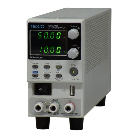
1-2. Appearance 1-2-1. Front Panel Function keys The Function keys along with the Output key will light up when a key is active. Voltage Knob Voltage Used to set the voltage value or select a parameter number in the Function settings. Current Knob Current Used to set the current value or change the value of... - Page 13 Set Key Used to set and confirm the output voltage and output current. M3 Key (+Shift) Used to recall the M3 setup. (+Shift and hold) Used to save the current setup to Shift Shift Key Used to enable the functions that are written in blue characters below certain buttons.
-
Page 14: Rear Panel
Lights up when CC Slew Rate Priority is enabled. Lights in red when an error has occurred. Lights up when the LAN remote connection is established. Lights in green when the memory value are being recalled or saved. Lights in green when the memory value are being recalled or saved. - Page 15 Output Terminals It uses a 10 pin connector and a plug for the output and sense terminal connectors. The plug is MC420-38110Z made by DECA SwitchLab. Positive (+) and negative (-) output terminals. +V N.C. N.C. Chassis ground Sense (-) and Sense (+) terminals. +V N.C.
-
Page 16: Theory Of Operation
PFR-100L50 Operating Area 100W Rated power Current (A) Voltage (V) PFR-100M250 Operating Area 100W Rated power Current (A) When the power supply is configured so that the total output (current x voltage output) is less than the rated power output, the power supply functions as a typical constant current, constant voltage power supply. -
Page 17: Cc And Cv Mode
1-3-2. CC and CV Mode CC and CV mode When the power supply is operating in constant current Description mode (CC) a constant current will be supplied to the load. When in constant current mode the voltage output can vary, whilst the current remains constant. When the load resistance increases to the point where the current limit ) can no longer be sustained the power supply switches to CV mode. -
Page 18: Slew Rate
1-3-3. Slew Rate Theory The PFR-100 has selectable slew rates for CC and CV mode. This gives the PFR-100 power supply the ability to limit the current/voltage draw of the power supply. Slew rate settings are divided into High Speed Priority and Slew Rate Priority. -
Page 19: Sink Current Table
1-3-5. Sink Current Table Background Sink current (reference value) from an external voltage source according to the bleeder circuit setting. PFR-100M250 Bleeder ON Bleeder OFF Vout Sink Current (mA) 0.135... -
Page 20: Alarms
This alarm function is activated when real output voltage is larger than sense output voltage. Vo_real > Vo_sense + 1.5V for PFR-100L50 Vo_real > Vo_sense + 2.5V for PFR-100M250 SENSE ALARM2 This alarm function is activated when sense output voltage is larger than real output voltage. - Page 21 value. The PFR-100 power supply ammeter only indicates mean current values, which means for pulsed current loads, the actual current can exceed the indicated value. For pulsed loads, the current limit must be increased, or a power supply with a greater capacity must be chosen. As shown below, a pulsed load may exceed the current limit and the indicated current on the power supply ammeter.
-
Page 22: Grounding
Reverse Current: When the power supply is connected to a load such as a Accumulative battery, reverse current may flow back to the power supply. energy To prevent damage to the power supply, use a reverse- current-protection diode in series between the power supply and load. - Page 23 If the insulation capacity of the load and load cables is not WARNING greater than the isolation voltage of the power supply, electric shock may occur. When the unit is analog controlled with external voltage control and external resistance control, the control signal should be floated without grounding (floating).
-
Page 24: Operation
2. OPERATION 2-1. Set Up 2-1-1. Power up Background Make sure that the power source is shut off. Use the AC power cable supplied with the product. Steps 1. Connect the power cord to the rear panel socket. 2. Press the POWER switch on. If used for the first time, the default settings will appear on the display, otherwise the PFR-100 recovers the state right before the power was last turned OFF. -
Page 25: The Rear Panel Output Terminal
2-1-3. The Rear Panel Output Terminal Background The PFR-100 series use a 10 pin socket for the output voltage and sense connections. The corresponding plugs (DECA SwitchLab MC420-38110Z) should be used to connect the terminals to the appropriate cable. Before connecting the output terminals to the load, first consider whether voltage sense will be used, the gauge of the cable wiring and the withstand voltage of the cables and load. -
Page 26: The Front Panel Output Terminal
5. Connect the positive load cable to the positive output terminal and the negative cable to the negative output terminal. Please note the wire gauge used and the capacity of the WARNING plug/socket. It may be necessary to wire the load to a number of terminals to offset the capacity over a number of terminals. -
Page 27: Using The Output Terminal Cover
For safety, Never output power through both the front and WARNING rear output terminals. 4. If necessary, connect the chassis ground terminal to either the -V or +V terminal. PFR-100L50 PFR-100M250 (GTL-201B) If using the front output +V terminal, it is necessary to connect the remote sensing cable on the back and the rear output connector. -
Page 28: Using The Rack Mount Kit
2-1-6. Using the Rack Mount Kit Background The PFR-100 series has an optional Rack Mount Kit: [JIS] GRA-431-J, [EIA] GRA-431-E) that can be used to hold 5 units into rack. Rack mount diagram 2-1-7. How to Use the Instrument Background The PFR-100 power supplies use a novel method of configuring parameter values only using the voltage or current knobs. -
Page 29: Reset To Factory Default Settings
Example Use the voltage knob to set a voltage of 10.05 volts. 1. Repeatedly press the voltage knob until the Voltage last digit is highlighted. This will allow the voltage to be edited in 0.01 volt steps. 2. Turn the voltage knob till 0.05 volts is shown. Voltage →... -
Page 30: View System Version And Build Date
4. Use the current knob to set the F-88 setting Current to 1 (Return to factory settings). 5. Press the Voltage knob to confirm. ConF Voltage will be displayed when successful. Function 6. Press the Function key again to exit. The function key light will turn off. - Page 31 F-89 0-XX : Main Program Version 1-XX : Main Program Version 2-XX : Main Program Build On-Year. 3-XX : Main Program Build On-Year. 4-XX : Main Program Build On-Month. 5-XX : Main Program Build On-Day. 6-XX : Keyboard CPLD version. 7-XX : Keyboard CPLD version.
-
Page 32: Basic Operation
OCP(A) OVP(V) UVL(V) PFR-100L50 1~11 5~55 0~52.5 PFR-100M250 0.2~2.2 5~275 0~262.5 You can use the Function settings (F-13 and F-14) to apply limits to the voltage and current settings, respectively. You can set Note limitations so that the values do not exceed the set OVP and the set OCP level, and so that the values are not lower than the set UVL trip point. - Page 33 about 95% of the OCP trip point. PROT Steps 1. Press the PROT key. The PROT key lights ALM_CLR OVP Setting 2. The OVP function will be displayed on the voltage display and the setting will be displayed on the current display. OVP function OVP setting OVP Level...
-
Page 34: Set To Cv Mode
3. Turning the Voltage knob to the right until the Voltage UVL function will be displayed on the voltage display and the setting will be displayed on the current display. UVL function UVL setting UVL Level 4. Use the Current knob to set the UVL level. Current Range 5V~105% of rated output voltage... - Page 35 3~5 to set F-04 (Rising Voltage Slew Rate) and the F-05 (Falling Voltage Slew Rate) and save. F-04 / F-05 0.1V/s~100.0V/s (PFR-100L50) 0.1V/s~500.0V/s (PFR-100M250) Function 6. Press the Function key again to exit the configuration settings. The function key light will turn off.
-
Page 36: Set To Cc Mode
CV will become illuminated Only the voltage level can be altered when the output is on. Note The current level can only be changed by pressing the Set key. For more information on the Normal Function Settings, see page 40. 2-2-3. - Page 37 5. If CC Slew Rate Priority was chosen as the operating mode, set F-06 (Rising Current Slew Rate) and F-07 (Falling Current Slew Rate) and save. F-06 / F-07 0.01A/s~20.00A/s (PFR-100L50) 0.001A/s~4.000A/s (PFR-100M250) Function 6. Press the Function key again to exit the configuration settings. The function key light will turn off.
-
Page 38: Display Modes
2-2-4. Display Modes The PFR-100 power supplies allow you to view the output in three different modes: voltage and current, voltage and power or current and power. Shift Steps 1. Hold the PWR_DSPL (SHIFT) key for 3 seconds. The display change to voltage and power (V/W). -
Page 39: Preset Memory
2-2-6. Preset Memory The PFR-100 has three preset memories (M1, M2, M3) and can save and recall the set current, set voltage, OVP, OCP and UVL settings. Save Setup 1. Make this unit the setting you want to save. Shift 2. -
Page 40: Remote Sensing
Remote sense can compensate up to 1 volts for PFR-100L50 and PFR-100M250 (compensation voltage). Load cables should be chosen with a voltage drop less than the compensation voltage. - Page 41 Wire Shielding and To help to minimize the oscillation due to the inductance Load line and capacitance of the load cables, use an electrolytic impedance capacitor in parallel with the load terminals. To minimize the effect of load line impedance use twisted wire pairing.
-
Page 42: Test Script
2-3. Test Script This section describes how to use the Test function to run, load and save test scripts for automated testing. The Test function is useful if you want to perform a number of tests automatically. The PFR-100 test function can store one test script at a time in memory. -
Page 43: Load Test Script From Usb Drive
Test Setting Loaded indication 3. Rotate the Voltage knob to change the T Voltage setting (Test setting). Test Run T-01 Test Load T-02 Test Export T-03 Test Remove T-04 Available Test Memory T-05 4. Rotate the Current knob to choose a memory Current number. -
Page 44: Run Test Script
If the USB drive is not recognized, check to see that the Note function settings for F-20 = 1 (page 45). If not, reinsert the USB flash drive. If you want to use the USB flash driver, F29 can’t be set to 3 3. -
Page 45: Export Test Script To Usb
Output 4. To execute the script, press the Output key. The Output key becomes illuminated. When the script is executing, the measurement results will display as normal. The Test LED will flash. When a script is running, press the Output key again to Note return the script engine to the wait state. -
Page 46: Remove Test Script
If the USB drive is not recognized, check to see that the Note function settings for F-20 = 1 (page 45). If not, reinsert the USB flash drive. If you want to use the USB flash driver, F-29 can’t be set to 3. 3. -
Page 47: Setting Values Of The Test Script
Sample file memo,2017/10/1,,,,,,,,,,,, DisplayItems,VI,,,,,,,,,,,, CycleItems,Number,Start Step,End Step,,,,,,,,,, Cycle,3,1,5,,,,,,,,,, Step,Point,Output,Time(sec),Voltage(V),Current(A),OVP(V),OCP(A),Ble eder,IV Mode,Vsr up(V/s),Vsr down(V/s),Isr up(A/s),Isr down(A/s) 1,Start,On,0.5,0,1,MAX,MIN,ON,CVHS,MAX,MAX,MAX,MAX 2,,On,0.5,0.05,,,,,,,,, 3,,On,0.5,0.1,,,,,,,,, 4,,On,0.5,0.15,,,,,,,,, 5,End,On,0.5,0.2,,,,,,,,, 2-3-10. Setting values of the test Script The number of steps is limited to free memory area, but it is up to step up to 100. Setting of time is 0.01 seconds resolution, 0.05 seconds in the shortest. - Page 48 Setting Values Unit Value Step (mandatory) Title / Number “Step” Point (mandatory) START: 1 “Point” END: Last Point Mid: Blank OUTPUT (mandatory) ON/OFF “Output” Holding time (mandatory) 0, 0.05~1000000.00 “Time(sec)” Resolution: 0.01 sec 0: Skip the execution (Time error occurs total time lag will occur Skip.) Voltage Value or MAX/MIN (See ratings)
-
Page 49: Configuration
V-I mode slew rate select 2 = CV slew rate priority (CVLS) 3 = CC slew rate priority (CCLS) F-04 0.1V/s~100.0V/s (PFR-100L50) Rising voltage slew rate 0.1V/s~500.0V/s (PFR-100M250) F-05 0.1V/s~100.0V/s (PFR-100L50) Falling voltage slew rate 0.1V/s~500.0V/s (PFR-100M250) F-06 0.01A/s~20.00A/s (PFR-100L50) Rising current slew rate 0.001A/s~4.000A/s (PFR-100M250) - Page 50 USB/GP-IB settings Front panel USB State* F-20 0 = None, 1 = Mass Storage Rear panel USB State* F-21 0 = None, 1 = Linking to PC GP-IB address F-23 0~30 Show GPIB available F-25 0 = No GP-IB, 1 = GP-IB is available status* 0 = Disable, 1 = RS-232C, 2 = RS-485, 3 = USB-CDC / NO Mass Storage,...
- Page 51 Displayed parameter: AA-S UART Multi-Drop status F-78 AA: 00~30 (Address), S: 0~1 (Off-line / On-line status) System Settings 0 = Disable Factory Set Value F-88 1 = Return to factory default settings 0, 1 = PFR-100 version 2, 3 = PFR-100 build year Show Version F-89 4, 5...
-
Page 52: Normal Function Settings
3-2. Normal Function Settings Output ON Delay Delays turning the output on for a designated amount of Time time. The Delay indicator will light when the Delay time is not 0. Note: The Output ON Delay Time setting has a maximum deviation (error) of 20ms. - Page 53 Sets the rising voltage slew rate. Only applicable if V-I Slew Rate Mode is set to CV Slew Rate Priority. F-04 0.1V/s~100.0V/s (PFR-100L50) 0.1V/s~500.0V/s (PFR-100M250) Falling Voltage Sets the falling voltage slew rate. Only applicable if V-I Slew Rate Mode is set to CV Slew Rate Priority.
-
Page 54: Usb / Gp-Ib Settings
F-14 0 = OFF (The limit function of voltage setting is disabled.) 1 = ON (The limit function of voltage setting is enabled.) Memory Recall When the preset memory (M1, M2, M3) is recalled, the Display setting value will blink. F-15 0 = OFF, 1 = ON Measurement... -
Page 55: Uart Settings
DNS Address Sets the DNS address. The DNS address is split into four parts. F-51~F-54 0~255 Web Password Turns a web password on / off. active F-60 0 = Enable, 1 = Disable Web Password Sets the Web password. F-61 0000~9999 3-5. -
Page 56: Power On Configuration Settings
F-89 0, 1 = PFR-100 version 2, 3 = PFR-100 build year 4, 5 = PFR-100 build month/day 6, 7 = Keyboard CPLD version 8, 9 = Analog-Control CPLD version 3-7. Power On Configuration Settings CV Control Sets the constant voltage (CV) control mode between local and external voltage/resistance control. -
Page 57: Setting Normal Function Settings
3-9. Setting Normal Function Settings The Normal Function settings, F-01~F-61, F-71~F-78, F-88, F-89 can be easily configured with the Function key. Ensure the load is not connected. Ensure the output is off. Function settings F-90~F-94 can only be viewed. Function setting F-20、... -
Page 58: Setting Power On Configuration Settings
3-10. Setting Power On Configuration Settings Background The Power On configuration settings can only be changed during power up to prevent the configuration settings being inadvertently changed. Ensure the load is not connected. Ensure the power supply is off. Steps 1. -
Page 59: Analog Control
4. ANALOG CONTROL The Analog Control chapter describes how to control the voltage or current output using an external voltage or resistance, monitor the voltage or current output as well as remotely turning off the output or shutting down the power supply. 4-1. - Page 60 Pin name Pin number Description Status COM This is the common line for the status signal pins 2 to 6. Alarm Status On when a protection function (OVP, HW_OVP, OCP, OHP, AC_FAIL or OPP) has been activated or when an output shutdown signal is being applied (open-collector photocoupler output).* CV Status...
-
Page 61: External Voltage Control Of Voltage Output
EXT-V/R CC 18 This line uses an external voltage or resistance to control the CONT output current. External voltage control (F-91: 1); External resistor control (F-91: 2, F-91: 3) 0 to 10V or 0 to 10kΩ or 10k to 0Ω; 0% to 100% of the rated output current. - Page 62 EXT-V PFR-100 0V~10V + Analog connector - A COM 2 core shielded wire or twisted Output pair Terminal Pin 16 → EXT-V(+) A COM (either Pin 13, 15 or 17) → EXT-V (-) Wire shield → EXT-V ground (GND) Panel operation 1.
-
Page 63: External Voltage Control Of Current Output
CV and CC Slew Rate Priority are disabled for V-I mode Note (F-03) when using external voltage control. See the Normal Function Settings on page 43. During external voltage control, the output on and off delay times are disabled. 4-1-3. External Voltage Control of Current Output Background External voltage control of the current output is accomplished using the MIL-26 connector on the rear... -
Page 64: External Resistance Control Of Voltage Output
Be sure to cycle the power after the power on configuration has been set. Function 3. Press the Function key and confirm the new configuration settings (F-91 = 1). Output 4. Press the Output key. The current can now be controlled with the External voltage. - Page 65 The Ext-R configuration is recommended for safety Note reasons. In the event that the cables become accidentally disconnected, the voltage output will drop to zero. Under similar circumstances using Ext-R , an unexpected high voltage would be output. If switches are used to switch between fixed resistances, use switches that avoid creating open circuits.
-
Page 66: External Resistance Control Of Current Output
For external resistors, use a metal film resistor or a wire Note wound resistor, such as a 1/2W or higher, low temperature coefficient and secular change. Please connect the wiring with 2 core shielding line or twisted pair cable briefly. Please do not be affected by foreign noises. -
Page 67: External Control Of Output
Steps 1. Connect the external resistance according to the connection diagrams above. 2. Set the F-91 (CC Control) configuration Page 49 settings to 2 for Ext-R or 3 for Ext-R Be sure to cycle the power after the power on configuration has been set. - Page 68 When set to High = On (F-94: 0), the output is turned on when A COM - Out On/Off CONT (pin 14) are open. When set to Low = On (F-94: 1), the output is turned on when A COM - Out On/Off CONT (pin 14) are shorted. Disable this function when F-94: 2.
-
Page 69: External Control Of Shutdown
Output off (High=on) Output off (Low=on) Output ON/OFF Delay Time (F-01, F-02) are disabled Note when the output is set to external control. See the normal function settings on page 43 for details. 4-1-7. External control of Shutdown Background The output of the power supplies can be configured to shut down via an external switch. -
Page 70: External Control Of Alarm Clear
Ensure the cables and switch used exceed the isolation WARNING voltage of the power supply. For example: insulation tubes with a withstand voltage higher than the power supply can be used. When using a switch over long distances, please use a Note switch relay to extend the line from the coil side of the relay. -
Page 71: Remote Monitoring
Steps 1. Connect the external switches according to the connection diagrams above. 2. Generate some alarm, set the alarm condition, short the switch, and confirm that the alarm is cleared. Ensure the cables and switch used exceed the isolation WARNING voltage of the power supply. -
Page 72: External Operation And Status Monitoring
IMON Connection PFR-100 Analog connector I MON I MON → A COM Output Terminal A COM (either Pin 13, 15 or 17) → Neg (-) Pin 19 → Pos (+) As for the monitor signal, there might be the electric shock WARNING in the floating output or the series driving for output terminal electric potential. - Page 73 CC Status This line is On when the PFR-100 is in CC mode (open-collector photocoupler output). Out On Status 6 On when the output is on (open-collector photocoupler output). Pins 2, 3, 4, 5, 6 Status COM Timing diagrams Below are 4 example timing diagrams covering a number of scenarios.
- Page 74 CC MODE: Output The diagram below shows the timing diagram when the turned on output is turned on when the PFR-100 is set to CC mode. CV Status CC Status OFF→ON Out On Status CC MODE: Output The diagram below shows the output status lines when the turned off output is turned off in CC mode.
-
Page 75: Communication Interface
5. Communication Interface This chapter describes basic configuration of IEEE488.2 based remote control. For a command list, refer to the programming manual. 5-1. USB Interface 5-1-1. USB Remote Interface When using the USB Remote Interface, The USB port on the Note front panel will become disabled and fail to be used. -
Page 76: Usb-Cdc Remote Control Function Check
*IDN? This should return the Manufacturer, Model name, Serial number, and Firmware version in the following format. TEXIO,PFR-100L50,TW1234567,01.01.12345678 Manufacturer : TEXIO Model name : PFR-100L50 Serial number : TW1234567 Firmware version : 01.01.12345678 Termination character of commands and queries use the ^j (LF: Line Feed). -
Page 77: Gpib Function Check
GPIB constraints Maximum 15 devices altogether, 20m cable length, 2m between each device. Unique address assigned to each device. At least 2/3 of the devices turned On. No loop or parallel connection. 5-2-2. GPIB Function Check Background To test the GPIB functionality, National Instruments Measurement and Automation Explorer can be used. - Page 78 3. Select the device (GPIB address of PFR-100) that now appears in the System>Devices and Interfaces > GPIB-USB-HS “GPIBX” node. 4. Click on the VISA Properties tab on the bottom. 5. Click Open Visa Test Panel. 6. Click on Configuration. 7.
- Page 79 13. Enter *IDN? in the Select or Enter Command drop down box. 14. Click Query. 15. The *IDN? query will return the Manufacturer, model name, serial number and firmware version in the dialog box. TEXIO,PFR-100L50,TW1234567,01.01.12345678 TEXIO,PFR-100L50,TW1234567,01.01.12345678\n For further details, please see the programming manual. Note...
-
Page 80: Lan Interface
5-3. LAN Interface The Ethernet interface can be configured for a number of different applications. Ethernet can be configured for basic remote control or monitoring using a web server or it can be configured as a socket server. The PFR-100 series supports both DHCP connections so the instrument can be automatically connected to an existing network or alternatively, network settings can be manually configured. -
Page 81: Web Server Remote Control Function Check
255.255.255.0 192.168.0.1 0.0.0.0 00-11-22-AA-BB-02 TCPIP0::192.168.0.103::2268::SOCKET Copyright 2017 ⓒ TEXIO TECHNOLOGY CORPORATION All Rights Reserved. The web browser interface allows you to access the following: Network configuration settings Measurement setting Normal Function setting Power On Configuration setting... -
Page 82: Socket Server Configuration
5-3-3. Socket Server Configuration Configuration This configuration example will configure the PFR-100 socket server. The following configuration settings will manually assign the PFR-100 an IP address and enable the socket server. The socket server port number is fixed at 2268. 1. - Page 83 Display and operated by a version of NI-MAX is different. Please operate in accordance with the version you are using. 2. From the Configuration panel access My System>Devices and Interfaces>Network Devices 3. Press Add New Network Device>Visa TCP/IP Resource... 4. Select Manual Entry of Raw Socket from the popup window. 5.
- Page 84 9. Next configure the Alias (name) of the PFR-100 connection. Example:PFR-100_DC1 10. Click finish. 11. The IP address of the PFR-100 will now appear under Network Devices in the configuration panel. Select this icon now. 12. Press Open VISA Test Panel. 13.
- Page 85 19. Click the Query button. 20. The *IDN? query will return the Manufacturer, model name, serial number and firmware version in the dialog box. TEXIO,PFR-100L50,TW1234567,01.01.12345678 Manufacturer: TEXIO Model name : PFR-100L50 Serial number : TW1234567 Firmware version : 01.01.12345678 TEXIO,PFR-100L50,TW1234567,01.01.12345678 For further details, please see the programming manual.
-
Page 86: Serial Interface
5-4. Serial Interface 5-4-1. UART Remote Interface The PFR-100 uses the IN & OUT ports for UART communication coupled with RS232 (Part number: GTL-259) or RS485 adapters (Part number: GTL-260). When using only one unit with RS485, connect the end terminal connector to Remote-OUT. -
Page 87: Uart Function Check
*IDN? This should return the Manufacturer, Model number, Serial number, and Firmware version in the following format: TEXIO,PFR-100L50,TW1234567,01.01.12345678 Manufacturer: TEXIO Model name : PFR-100L50 Serial number : TW1234567 Firmware version : 01.01.12345678 ^j (LF:Line Feed) can be used as the terminal character when entering the queries/commands from a terminal application. -
Page 88: Multidrop Interface
5-5. Multidrop Interface 5-5-1. Multiple Unit Connection The PFR-100 power supplies can have up to 31 units daisy-chained together using the 8 pin connectors (Remote-IN OUT ports) on the rear panel. The first unit (master) in the chain is remotely connected to a PC using USB, GPIB or LAN (Multi-Drop mode). - Page 89 GPIB Terminator Master Slave Cable Cable Master Unit #2 Unit #N 6. Power up all slave units. 7. Set the addresses of all slave units using the F-76 parameter. F-76 = 00~30 Set the address of the master unit. It must be a unique address identifier. 8.
-
Page 90: Multi-Drop Mode Function Check
Multi-Drop mode. See page 79. ← Press ENTER after typing. :INST:SEL 0 ← Press ENTER after typing. *IDN? TEXIO,PFR-100L50,TW1234567,01.01.12345678 ← Press ENTER after typing. :INST:SEL 5 ← Press ENTER after typing. *IDN? TEXIO,PFR-100L50,TW7654321,01.01.12345678 ←... - Page 91 ← Press ENTER after typing. :SYST:ERR? Settings conflict Query the system errors. “Settings conflict” is returned. ← Press ENTER after typing. :INST:STAT? 33,0 Returns the active units and master unit in the bus. 33 = 0b100001 The units at address 0 and address 5 are on-line. Master device's address is 0.
-
Page 92: Faq
6. FAQ How often should the power supply be calibrated? The PFR-100 should be calibrated by an authorized service center at least every 2 years. For details regarding calibration, see your local dealer or our website. The power supply won’t let me change the mode (CVmode ↔ CCmode). To set the power supply to CC or CV mode, the Function key must be held when the power is turned on to enter the Power On Configuration Mode. -
Page 93: Appendix
Output OFF Delay Time F-02 0.00s V-I Mode Slew Rate Select F-03 0 = CV high speed priority F-04 100.0V/s (PFR-100L50) Rising Voltage Slew Rate 500.0V/s (PFR-100M250) F-05 100.0V/s (PFR-100L50) Falling Voltage Slew Rate 500.0V/s (PFR-100M250) 20.00A/s (PFR-100L50) Rising Current Slew Rate F-06 4.000A/s (PFR-100M250) -
Page 94: Error Messages & Messages
UART TCP F-75 0 = SCPI Power On Configuration Setting Default Setting Setting CV Control F-90 0= Panel control (local) CC Control F-91 0= Panel control (local) Power ON Output F-92 0 = Safe Mode (Output OFF at startup) External Out Logic Control F-94 0 = High ON Data of the test script is not cleared by the initialization by F-88. -
Page 95: Led Ascii Table Character Set
7-3. LED ASCII Table Character Set Use the following table to read the LED display messages. 7-4. Test Script Error Code The following error code is in Test Script. Code No. Description No error -1 ~ -8 File format errors, control character errors, undefined words, etc. -9 ~ -19 Number of cycles error -20 ~ -29... -
Page 96: Specification List
8. Specification list The specifications apply when the PFR-100 is powered on for at least 30 minutes. 8-1. Rating 8-1-1. Output Model name PFR- 100L50 100M250 Rated Output Voltage Rated Output Current Rated Output Power Power ratio 8-1-2. Constant Voltage Mode Model name PFR- 100L50... -
Page 97: Protection Function
8-1-4. Protection Function Model name PFR- 100L50 100M250 Over voltage protection Setting range 5 - 55 5 - 275 (OVP) Setting accuracy V 0.50 Over current protection Setting range 1 - 11 0.2 - 2.2 (OCP) Setting accuracy A 0.20 0.040 Under voltage limit Setting range... -
Page 98: Front Panel
8-1-6. Front Panel Model name PFR- 100L50 100M250 Output voltage setting range 0 - 52.5 0 - 262.5 Output voltage resolution Output current setting range 0 - 10.5 0 - 2.1 Output current resolution Display, 4 digits Volatge 0.1% of accuracy reading + Current... -
Page 99: Input Characteristics
8-1-8. Input Characteristics Model name PFR- 100L50 100M250 Input voltage range 85 - 265 85 - 265 Input frequency range 47 - 63 47 - 63 100Vac 1.44 Maximum input current 200Vac 0.75 0.72 Inrush current Less than 20A Maximum input power 100Vac 0.98 0.98... -
Page 100: General Specifications
8-1-11. General Specifications Model name PFR- 100L50 100M250 Weight main unit only Approx. 2.5kg Dimensions (W×H×D) 71×124×301 Cooling Natural convection cooling. Complies with the European EMC directive 2014/30/EU for Class A test and measurement products. Complies with the European Low Voltage Safety directive 2014/35/EU and carries the CE-marking. -
Page 101: Dimensions
8-2. PFR-100 Dimensions... - Page 102 7F Towa Fudosan Shin Yokohama Bldg. 2-18-13, Shin Yokohama, Kohoku-ku,Yokohama, Kanagawa, 222-0033 Japan http://www.texio.co.jp/...
Need help?
Do you have a question about the PFR-100M250 and is the answer not in the manual?
Questions and answers