Table of Contents
Advertisement
Advertisement
Table of Contents

Related Manuals for TEXIO PU6-200


Summary of Contents for TEXIO PU6-200
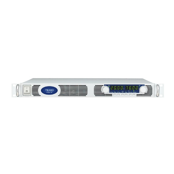
- Page 1 1500W SERIES DC POWER SUPPLY PU SERIES PU6-200 6V/200A PU8-180 8V/180A PU12.5-120 12.5V/120A PU20-76 20V/76A PU30-50 3V/50A PU40-38 40V/38A PU60-25 60V/25A PU80-19 80V/19A PU100-15 100V/15A PU150-10 150V/10A PU300-5 300V/5A PU600-2.6 600V/2.6A INSTRUCTION MANUAL © PRINTED IN JAPAN B65-0168-28...
-
Page 3: Table Of Contents
CONTENTS WARRANTY............................Ⅰ SAFETY INSTRUCTIONS..................................Ⅱ GENERAL INFORMATION ........................1 1.1. USER MANUAL CONTENT ..............................1 1.2. INTRODUCTION ..................................1 1.2.1 General description ................................1 1.2.2 Models covered by this manual ............................1 1.2.3 Features and options................................2 1.2.4 Multiple output power system............................2 1.2.5 Control via the serial communication port........................2 1.2.6 Analog voltage programming and monitoring.......................2 1.2.7 Parallel operation..................................3 1.2.8 Output connections................................3... - Page 4 3.7. AC INPUT POWER CONNECTION ..........................11 3.7.1 AC Input Connector ................................11 3.7.2 AC Input Cord..................................11 3.7.3 AC Input Wire Connection, 1500W models........................ 11 3.7.4 Time to Heat Beforehand..............................12 3.8. TURN-ON CHECKOUT PROCEDURE......................... 12 3.8.1 General ....................................12 3.8.2 Prior to Operation................................
- Page 5 4.5.1 Making J1 connections ..............................30 LOCAL OPERATION ........................32 5.1. INTRODUCTION ................................... 32 5.2. STANDARD OPERATION ..............................32 5.2.1 Constant Voltage Mode ..............................32 5.2.2 Constant Current Operation............................33 5.2.3 Automatic Crossover................................. 33 5.3. OVER VOLTAGE PROTECTION (OVP)........................33 5.3.1 Setting the OVP level................................
- Page 6 6.5. RESISTIVE PROGRAMMING OF OUTPUT VOLTAGE AND CURRENT LIMIT .......... 46 6.6. REMOTE MONITORING OF OUTPUT VOLTAGE AND CURRENT ..............47 RS232 & RS485 REMOTE CONTROL....................49 7.1. INTRODUCTION ................................... 49 7.2. CONFIGURATION ................................49 7.2.1 Default setting..................................49 7.2.2 Address setting..................................49 7.2.3 RS232 or RS485 selection...............................
- Page 7 ISOLATED ANALOG PROGRAMMING OPTION................. 64 NTRODUCTION ..........................64 8.1. 8.2. SPECIFICATIONS ................................64 8.2.1 0-5V/0-10V option ................................64 8.2.2 4-20mA option ..................................64 8.3. ISOLATED PROGRAMMING & MONITORING CONNECTOR................65 8.4. SETUP AND OPERATING INSTRUCTIONS......................66 8.4.1 Setting up the power supply for 0-5/0-10V Isolated Programming and Monitoring........ 66 8.4.2 Setting up the power supply for 4-20mA Isolated Programming and Monitoring........
- Page 9 QA seal has been removed or altered by anyone other than TEXIO authorized personnel. TEXIO does not warrant the buyer’s circuitry or malfunctions of TEXIO products resulting from the buyer’s circuitry.
-
Page 10: Safety Instructions
Do not connect the Positive Output to ground when using the RS232/485 or IEEE. FUSES Fuses must be changed by authorized TEXIO service personnel only. For continued protection against risk of fire, replace only with the same type and rating of fuse. Refer to maintenance instructions in chapter 9 for fuses rating. - Page 11 To avoid injuries, always disconnect power, discharge circuits and remove external voltage source before touching components. PARTS SUBSTITUTIONS&MODIFICATIONS Parts substitutions and modifications are allowed by authorized TEXIO service personnel only. For repairs or modifications, the instrument must be returned to TEXIO service facility. ENVIRONMENTAL CONDITIONS...
- Page 12 FCC COMPLIANCE NOTICE: Note: This equipment has been tested and found to comply with the limits for a Class A digital device, pursuant to part 15 of the FCC Rules. These limits are designed to provide reasonable protection against harmful interference when the equipment is operated in a commercial environment. This equipment generates uses, and can radiate radio frequency energy and, if not installed and used in accordance with the instruction manual, may cause harmful interference to radio communications.
-
Page 13: General Information
1. GENERAL INFORMATION 1.1. USER MANUAL CONTENT This user’s manual contains the operating instructions, installation instructions and specifications of the PU 1500W power supply series. The instructions refer to the standard power supplies, including the built-in RS232/485 serial communication. For information related to operation with the optional IEEE programming, refer to User Manual for Power Supply IEEE programming Interface. -
Page 14: Features And Options
1.2.3 Features and options * Constant Voltage / Constant Current with automatic crossover. * Active Power Factor correction. * Universal Input Voltage 85-265Vac, continuous operation. * Embedded Microprocessor Controller. * Built in RS232/485 Interface. * Voltage & Current high resolution adjustment by digital encoders. * High accuracy programming/readback-16 bit. -
Page 15: Parallel Operation
1.2.7 Parallel operation PU power supplies of the same output voltage and current rating can be paralleled in master-slave configuration with automatic current sharing to increase power available. 1.2.8 Output connections Output connections are made to rear panel bus-bars for models up to 60V and to a 4-terminal wire clamp connector for models above 60V rated output voltage. -
Page 16: Ac Cables
1.3.4 AC cables Please prepare AC cable with the following specification for 1500W model. 25A 250V, 12AWG or 10AWG (3 Core Wire) Outer diameter : 9-11mm Rated temperature : 60℃ or more Length : 3m or less Please use safety approved plug in each country. 1.3.5 Serial Port Cables Refer to section 7.4... -
Page 17: Specifications
2. SPECIFICATIONS 2.1. OUTPUT RATING MODEL 6-200 8-180 12.5-120 20-76 30-50 40-38 60-25 80-19 100-15 150-10 300-5 600-2.6 1.Rated output voltage(*1) 12.5 2.Rated output current 1500w(*2) 3.Rated output power 1500w 1200 1440 1500 1520 1500 1520 1500 1520 1500 1500 1500 1560 2.2. -
Page 18: Analog Programming And Monitoring
2.5. ANALOG PROGRAMMING AND MONITORING 1.volt voltage programming 0-100%,0-5V/ 0-10V,user select, Accuracy and linearity:±0.5% of rated Volt. 2.Iout voltage programming 0-100%,0-5V /0-10V,user select, Accuracy and linearity:±1% of rated Iout. 3.Vout resistor programming 0-100%,0-5/0~10kΩfull scale, user select, Accuracy and linearity:±1% of rated Volt. 4.Iout resistor programming 0-100%,0-5/0~10kΩfull scale, user select, Accuracy and linearity:±1.5% of rated Iout. -
Page 19: Environmental Conditions
2.9. ENVIRONMENTAL CONDITIONS 1.Operating temperature 0~50℃,100% load. 2. Storage temperature -20~70℃ 3. Operating humidity 30~90% RH (no condensation) 4. Storage humidity 10~95% RH (no condensation) Altitude Maximum 3000m. Derate output current by 2%/100m above 2000m. Alternatively, derate maximum ambient temperature by 1℃/100m above 2000m. 2.10. - Page 20 OUTLINE DRAWINGS Note 4 Note 1 Note 2 Note 3 Bus-Bar Detail NOTES: 6V to 60V Models 1. Mating plug supplied with power supply. 2. Bus-bars for 6V to 60V models. See detail. Wire clamp connector for 80V to 600V models (shown). 3.
-
Page 21: Installation
INSTALLATION 2.13. GENERAL This chapter contains instructions for initial inspection, preparation for use and repackaging for shipment. Connection to PC, setting the communication port and linking PU power supplies are described in Chapter 7. NOTE PU power supplies generate magnetic fields, which might affect the operation of other instruments. -
Page 22: Rack Mounting
2.16. RACK MOUNTING The PU power supply series is designed to fit in a standard 19” equipment rack. 3.4.1 To install the Power Supply in a rack: 1. Use the front panel rack-mount brackets to install the power supply in the rack. 2. -
Page 23: Ac Input Power Connection
2.19. AC INPUT POWER CONNECTION CAUTION Connection of this power supply to an AC power source should be made by an electrician or other qualified personnel. WARNING There is a potential shock hazard if the power supply chassis (with cover in place) is not connected to an electrical safety ground via the safety ground in the AC input connector WARNING Some components inside the power supply are at AC voltage even... -
Page 24: Time To Heat Beforehand
3. Slide the helix-shaped body onto the AC cable. Insert the stripped wires through the strain relief base until the outer cable jacket is flush with the edge of the base. Tighten (1.8-2.0 Nm / the body to the base while holding the cable in place. Now the cable is securely 18.4-20.7 kgf・cm) fastened inside the strain relief. -
Page 25: Prior To Operation
3.8.2 Prior to Operation 1. Ensure that the power supply is configured to the default setting: -AC On/Off switch at Off position. -Dip switch: All positions at Down (”Off”) position. -Sense connector: Configured to Local Sense as shown in Fig.3-4: 1 Remote (+) sense 2 Local (+) sense 3 Not connected... -
Page 26: Ovp Check
3.8.5 OVP Check Refer to Section 5.3 for explanation of the OVP function prior to performing the procedure below. 1. Turn the front panel AC power switch to On position and turn on the output by pressing OUTPUT pushbutton. 2. Using the VOLT encoder, adjust the output voltage to approx.10% of the unit voltage rating. 3. -
Page 27: Address Setting
3.8.8 Address Setting 1. Press and hold the RMT/LCL button for approx. 3sec. The VOLT display will show the communication port address. 2. Using the VOLT adjust encoder, check that the address can be set within the range of 0 to 30. 3.8.9 Baud Rate Setting 1. -
Page 28: Wire Termination
Table 3-2: Maximum wire length for 1V drop on lead (in feet) Maximum length in Feet to limit Wire size Resistivity voltage drop to 1V or less Ω/1000ft 150A 2.526 1.589 0.9994 0.6285 0.3953 0.2486 0.1564 1200 0.0983 2000 1000 Table 3-3: Maximum wire length for 1V drop on lead (in meters) Cross sect. -
Page 29: Noise And Impedance Effects
3.9.4 Noise and Impedance Effects To minimize the noise pickup or radiation, the load wires and remote sense wires should be twisted pairs to the shortest possible length. Shielding of sense leads may be necessary in high noise environments. Where shielding is used, connect the shield to the chassis via a rear panel Ground screw. - Page 30 Fig. 3-5: Load wires connection, 6V to 60V models. Fig. 3-6: Bus-bars shield mounting 80V to 600V Models WARNING Hazardous voltages exist at the outputs and the load connections. To protect personnel against accidental contact with hazardous voltages, ensure that the load and its connections have no accessible live parts. Ensure that the load wiring insulation rating is greater than or equal to the maximum output voltage of the power supply.
- Page 31 The 80V to 600V models have a four terminal wire clamp output connector. The two left terminals are the positive outputs and the other two right terminals are the negative outputs. The connector requirements are as follows: 1. Wires: AWG18 to AWG10. 2.
-
Page 32: Connecting Single Loads, Local Sensing (Default)
Fig.3-9: Protective shield and wires assembly 3.9.7 Connecting single loads, local sensing (default). Fig.3-10 shows recommended load and sensing connections for a single load. The local sense lines shown are default connections at the rear panel J2 sense connector. Local sensing is suitable for applications where load regulation is less critical. -
Page 33: Connecting Multiple Loads, Radial Distribution Method
3.9.9 Connecting multiple loads, radial distribution method Fig.3-12 shows multiple loads connected to one supply. Each load should be connected to the power supply’s output terminals using separate pairs of wires. It is recommended that each pair of wires will be as short as possible and twisted or shielded to minimize noise pick-up and radiation. The sense wires should be connected to the power supply output terminals or to the load with the most critical load regulation requirement. -
Page 34: Grounding Outputs
3.9.11 Grounding outputs Either the positive or negative output terminals can be grounded. To avoid noise problems caused by common-mode current flowing from the load to ground, it is recommended to ground the output terminal as close as possible to the power supply chassis ground. Always use two wires to connect the load to the power supply regardless of how the system is grounded. -
Page 35: Local Sensing
3.10.2 Local sensing The power supply is shipped with the rear panel J2 sense connector wired for local sensing of the output voltage. See Table 3-4 for J2 terminals assignment. With local sensing , the output voltage regulation is made at the output terminals. This method does not compensate for voltage drop on the load wires, therefore it is recommended only for low load current applications or where the load regulation is less critical. -
Page 36: J2 Sense Connector Technical Information
Use remote sense where the load regulation at the load end is critical. In remote sense, the power supply will compensate for voltage drop on the load wires. Refer to the power supply specifications for the maximum voltage drop on load wires. The voltage drop is subtracted from the total voltage available at the output. -
Page 37: Front And Rear Panel Controls And Connectors
3. FRONT AND REAR PANEL CONTROLS AND CONNECTORS 3.1. INTRODUCTION The PU Power Supply series has a full set of controls, indicators and connectors that allow the user to easily setup and operate the unit. Before starting to operate the unit, please read the following sections for explanation of the functions of the controls and connectors terminals. - Page 38 Table 4-1: Front Panel controls and indicators Number Control/Indicator Description Section 4 digits, 7-segment LED display, Normally displays the output current. When the V/I CHK button is CURRENT display pressed, the display indicates the programmed setting of output current. Green LED, lights for Constant-Current mode CC indicator operation.
-
Page 39: Rear Panel
Table 4-1: Front Panel controls and indicators Number Control/Indicator Description Section V/I CHK indicator Green LED, lights when V/I CHK button is pressed. Voltage and Current Fine/Coarse adjustment control. Operates as a toggle switch. In Fine mode, FINE button the VOLTAGE and CURRENT encoders operate with high resolution and in Coarse mode with lower resolution (approx. -
Page 40: Rear Panel Sw1 Setup Switch
Table 4-2: Rear panel connections and controls Number Item Description Section Remote Out RJ-45 type connector, used for chaining power supplies to form connector a serial communication bus. Connector for remote analog interface. Includes output voltage Programming and current limit programming and monitoring signals, Shut-off control (electrical signal), Enable/Disable control (dry-contact), Monitoring power supply ok (PS_OK) signal and operation mode (CV/CC) -
Page 41: Sw1 Position Functions
4.4.1 SW1 position functions Refer to Table 4-3 for description of SW1 position functions. The factory default setting is Down for all positions. Table 4-3: SW1 positions functions Position Function Down(Factory default) Output Voltage Output Voltage remote Output Voltage SW1-1 programmed by remote analog programming programmed by Front Panel... -
Page 42: Rear Panel J1 Programming And Monitoring Connector
3.5. REAR PANEL J1 PROGRAMMING AND MONITORING CONNECTOR The J1 Programming and Monitoring connector is a DB25 subminiature connector located on the power supply rear panel. Refer to Table 4-4 for description of the connector functions. The power supply default configuration is Local operation which does not require connections to J1. For remote operation using J1 signals use the plug provided with power supply or equivalent type. - Page 43 Fig.4-4: J1 connector terminals and functions Table 4-4: J1 connector terminals and functions Signal Function Reference contact name J1-1 ENA_IN Enable/Disable the power supply output by Sec.5-8 dry-contact (short/open) J1-2 IF_COM Isolated Interface Common. Return for the SO control, Sec.5-7,5-10 J1-3 PS_OK signal and for the optional IEEE interface.
-
Page 44: Local Operation
4. LOCAL OPERATION 4.1. INTRODUCTION This Chapter describes the operating modes that are not involved in programming and monitoring the power supply via its serial communication port (RS232/RS485) or by remote analog signals. Ensure that the RMT/LCL on the front panel is off, indicating Local mode. If the RMT/LCL LED is on, press the front panel RMT/LCL button to change the operating mode to local. -
Page 45: Constant Current Operation
5.2.2 Constant Current Operation 1. In constant current mode, the power supply regulates the output current at the selected value, while the voltage varies with the load requirement. 2. While the power supply is operating in constant current mode, the CCLED on the front panel illuminates. -
Page 46: Activated Ovp Protection Indications
To preview the OVP setting, press OVP/UVL Table 5-1: Maximum OVP setting levels pushbutton so that the CURRENT display will show "OUP". At this time, the VOLTAGE display will show the OVP setting. After 5 seconds, the display will return to it's previous state. Table 5-1: Maximum OVP setting levels 5.3.2 Activated OVP protection indications When the OVP is activated the power supply output shuts down. -
Page 47: Setting The Foldback Protection
5.5.1 Setting the Foldback protection To arm the Foldback protection, the FOLD button should be pressed so that the FOLD LED illuminates. In this condition, transition from Constant Voltage to Constant Current mode will activate the Foldback protection. Activation of the Foldback protection disables the power supply output, causes the ALARM LED to blink and display "... -
Page 48: Enable/Disable Control Via Rear Panel J1 Connector
Table 5-2: SO logic selection SO signal level Power supply SW1-5 setting Display J1-2(3), 15 output Down (default) 2-15V or Open Voltage/Current 0-0.6V or Short “SO” 2-15V or Open “SO” 0-0.6V or Short Voltage/Current 4.8. ENABLE/DISABLE CONTROL VIA REAR PANEL J1 CONNECTOR Contacts 1 and 14 of J1 (Fig.4-2, Item 5) serve as Output Enable/Disable terminals by switch or relay. -
Page 49: Ps_Ok Signal
5.10. PS_OK SIGNAL PS_OK signal indicates fault condition in the power supply. PS_OK is a TTL signal output at J1-16, referenced to IF_COM at J1-2, 3 (Isolated Interface Common)). When a fault condition occurs, PS_OK level is low, with maximum sink current of 1mA, when no fault condition occurs, PS_OK level is high with maximum source current of 2mA. -
Page 50: Last Setting Memory
4.13. LAST SETTING MEMORY The power supply is equipped with Last Setting Memory, which stores power supply parameters at each AC turn-off sequence. STOREDPARAMETERS: 1. Output voltage setting 2. Output constant・current mode・limit 3. OVP level 4. UVL level 5. FOLD setting 6. - Page 51 Fig.5-1: Series connection, local sensing Fig.5-2: Series connection, remote sensing Remote programming in series operation for increased output voltage: 1. Programming by external voltage: The analog programming circuits of this power supply are referenced to the negative Sense (-S) potential. Therefore, the circuits used to control each series connected unit must be separated and floated from each other.
-
Page 52: Series Connection For Positive And Negative Output Voltage
5.14.2 Series connection for positive and negative output voltage In this mode, two units are configured as a positive and negative output. Set the current limit of each power supply to the maximum that the load can handle without damage. It is recommended that diodes be connected in parallel with each unit output to prevent reverse voltage during start-up or in case one of the units shuts down. -
Page 53: Parallel Operation
4.15. PARALLEL OPERATION Up to four units of the same VOLTAGE and CURRENT rating can be connected in parallel to provide up to four times the output current capability. One of the units operates as a master and the remaining units are slaves. The slave units are analog programmed by the master unit. In remote digital operation, only the master unit can be programmed by the computer while the slave units may be connected to the computer for voltage, current and status readback only. -
Page 54: Daisy-Chain Connection
Fig.5-4: Parallel connection with local sensing NOTE With local sensing it is important to minimize the wire length and resistance. Also the positive and negative wire resistance should be close as possible to each other to achieve current balance between power supplies. Fig.5-5: Parallel operation with Remote sensing 4.16. -
Page 55: Front Panel Locking
Fig.5-6: Daisy-chain connection 4.17. FRONT PANEL LOCKING The front panel controls can be locked to protect from accidental power supply parameter change. Press and hold V/I CHK button to toggle between “Locked front panel” and “Unlocked front panel”. The display will cycle between “LFP” and “UFP”. Releasing the V/I CHK button while one of the modes is displayed, selects that mode. -
Page 56: Remote Analog Programming
5. REMOTE ANALOG PROGRAMMING 5.1. INTRODUCTION The rear panel connector J1 allows the user to program the power supply output voltage and current limit with an analog device. J1 also provides monitoring signals for output voltage and output current. The programming range and monitoring signals range can be selected between 0-5V or 0-10V using the setup switch SW1. -
Page 57: Remote Voltage Programming Of Output Voltage And Current Limit
5.4. REMOTE VOLTAGE PROGRAMMING OF OUTPUT VOLTAGE AND CURRENT LIMIT CAUTION To maintain the isolation of power supply and prevent ground loops, use an isolated programming source when operating the power supply via remote analog programming at J1 connector. Perform the following procedure to set the power supply to Remote Voltage programming: 1. -
Page 58: Resistive Programming Of Output Voltage And Current Limit
J1 connector, rear panel view Fig.6-1: Remote voltage programming connection 5.5. RESISTIVE PROGRAMMING OF OUTPUT VOLTAGE AND CURRENT LIMIT For resistive programming, internal current sources, for output voltage and/or output current control, supply 1mAcurrent through external programming resistors connected between J1-9 & 22 and 1-10 & 23. -
Page 59: Remote Monitoring Of Output Voltage And Current
Table 6-4: SW1-3 setting and programming range Output Voltage programming Current limit programming SW1-3 setting VPGM (J1-9) IPGM (J1-10) 0-10kΩ 0-10kΩ DOWN 0-5kΩ 0-5kΩ J1 connector, rear panel view Fig.6-2: Remote resistive programming 5.6. REMOTE MONITORING OF OUTPUT VOLTAGE AND CURRENT The J1 connector, located on the rear panel provides analog signals for monitoring the output voltage and output current. - Page 60 2. Front panel encoders operation: In Remote analog mode the output voltage and current can’t be set by the VOLTAGE and CURRENT encoders. 3. Front panel V/I CHK button: Use V/I CHK button to display the output voltage and current setting defined by the encoders or communication. 4.
-
Page 61: Rs232 & Rs485 Remote Control
6. RS232 & RS485 REMOTE CONTROL 6.1. INTRODUCTION This chapter describes the operation of the PU1500W power supplies via the serial communication port. Details of the initial set-up, operation via RS232 or RS485, the command set and the communication protocol are described in this chapter. 6.2. -
Page 62: Setting The Unit Into Remote Or Local Mode
7.2.5 Setting the unit into Remote or Local mode 1. The unit will be put into Remote mode only via serial communication command. Commands that will put the unit into Remote mode are: PV n OUT n PC n RMT n (for n values see Tables 7-4 and 7-6) 2. -
Page 63: Rear Panel Rs232/485 Connector
6.3. REAR PANEL RS232/485 CONNECTOR The RS232/485 interface is accessible through the rear panel RS232/485 IN and RS485 OUT connectors. The connectors are 8 contact RJ-45. The IN and OUT connectors are used to connect power supplies in a RS232 or RS485 chain to a controller. Refer to Fig.7-1 for IN/OUT connectors Fig.7-1: J3 rear panel IN/OUT connectors pinout NOTE Tx and Rx are used for RS232 communication. -
Page 64: Multi Power Supply Connection To Rs232 Or Rs485 Bus
Fig.7-3: RS232 cable with DB9 connector Fig.7-4: RS485 cable with DB9 connector 7.4.2 Multi power supply connection to RS232 or RS485 bus Up to 31 units can be connected to RS232 or RS485 bus. The first unit connects to the controller via RS232 or RS485 and the other units are connected with RS485 bus. -
Page 65: Termination
7.4.3 Termination Terminal resistor for output terminal of the last PU power supply unit is required when connecting two or more sets of power supplies using serial link cable or using “RS 485 cable with DB9 connector”. 8 pin connector (RJ-45) Terminal resistor Pin No. -
Page 66: Error Message
7.5.6 Error message If an error is detected in a command or query, the power supply will respond with an error message. Refer to section 7.6 for details. 7.5.7 Backspace The backspace character (ASCII 8) clears the last character sent to the power supply. 6.6. -
Page 67: Command Set Description
6.7. COMMAND SET DESCRIPTION 7.7.1 General guides 1. Any command or argument may be in capital letters or small letters. 2. In commands with an argument, a space must be between the command and the argument. 3. For any command that sets a numeric value, the value may be up to 12 characters long. 4. -
Page 68: Initialization Control Commands
7.7.4 ID control commands Command Description IDN? Returns the power supply model identification as an ASCII string. (Example: TEXIO, PU6-200) REV? Returns the software version as an ASCII string. Returns the unit serial number. Up to 12 characters. 7.7.5 Output control commands... - Page 69 Command Description OUT? Returns the output On/Off status string. ON-output on. OFF-output off. FLD n Sets the Foldback protection to ON or OFF. FLD 1(or FOLD ON)-Arms the Foldback protection. FLD 0(or FOLF OFF)-Cancels the Foldback protection. When the Foldback protection has been activated, OUT 1 command will release the protection and re-arm it, while FLD 0 will cancel the protection.
-
Page 70: Status Control Commands
PU 1500W models Table 7-4: Current programming range Model Minimum(A) Maximum(A) PU6-200 000.00 200.00 PU8-180 000.00 180.00 PU12.5-120 000.00 120.00 PU20-76 00.00 76.00 PU30-50 00.000 50.000 PU40-38 00.000 38.000 PU60-25 00.000 25.000 PU80-19 00.000 19.000 PU100-15 00.000 15.000 PU150-10 00.000 10.000... -
Page 71: Status, Error And Srq Registers
7.8. STATUS, ERROR AND SRQ REGISTERS 7.8.1 General This section describes the various status error and SRQ registers structure. The registers can be read or set via the RS232/485 commands. When using the IEEE option, refer to the user manual for PU Power Supply IEEE Programming interface. - Page 72 Table 7-8: Fault Condition Register Fault name Fault symbol Bit Set condition Bit Reset condition Spare bit SPARE Fixed to zero Fixed to zero 0(LSB) AC Fail AC fail has The AC input returns to normal. occurred. Over OTP shutdown has The power supply cool down.
-
Page 73: Service Request: Enable And Event Registers
7.8.3 Service Request: Enable and Event Registers The conditional Registers are continuously monitored. When a change is detected in a register bit which is enabled, the power supply will generate an SRQ message. The SRQ message is: "!nn" terminated by CR, where the nn is the power supply address. The SRQ will be generated either in Local or Remote mode. - Page 74 3. Status Enable register The Status Enable Register is set by the user to enable SRQs from changes in power supply status. Table 7-12: Status Enable Register Status Status name Bit Set condition Bit reset condition symbol User command: User command: 0(LSB) Constant Voltage “SENA nn”...
- Page 75 7.9. SERIAL COMMUNICATION TEST SET-UP Use the following instructions as basic set-up to test the serial communication operation. 1. Equipment: PC with Windows Hyper Terminal, private edition, software installed, PU power supply, RS232 cable. 2. PC set-up: 2.1 Open Hyper Terminal New Connection.
-
Page 76: Isolated Analog Programming Option
7. ISOLATED ANALOG PROGRAMMING OPTION 7.1. INTRODUCTION Isolated Analog Programming is an internal option card for analog programming of the PU power supply series. The option is factory installed and cannot be obtained with GPIB (IEEE) Interface. Output Voltage and Current Limit can be programmed and readback through optically isolated signals which are isolated from all other ground references in the power supply. -
Page 77: Isolated Programming & Monitoring Connector
7.3. ISOLATED PROGRAMMING & MONITORING CONNECTOR Refer to Table 8-1 for detailed description of the rear panel Isolated Programming & Monitoring connector. To provide the lowest noise performance, it is recommended to use shielded-twisted pair wiring. Refer to Fig.8-1 for description of the connector. Isolated programming plug P/N: MC1.5/8-ST-3.81, Phoenix. -
Page 78: Setup And Operating Instructions
7.4. SETUP AND OPERATING INSTRUCTIONS CAUTION To prevent damage to the unit, do not program the output voltage and current to higher then the power supply rating. 8.4.1 Setting up the power supply for 0-5/0-10V Isolated Programming and Monitoring Perform the following procedure to configure the power supply: 1. -
Page 79: Maintenance
8. MAINTENANCE 8.1. INTRODUCTION This chapter provides information about maintenance, calibration and troubleshooting. 8.2. UNITS UNDER WARRANTY Units requiring repair during the warranty period should be returned to a Lambda authorized service facility. Refer to the addresses listing on the back cover of this manual. Unauthorized repairs performed by other than the authorized service facilities may void the warranty. -
Page 80: Fuse Rating
SYMPTOM CHECK ACTION REF. Output is present momentarily Is the power supply Check if the positive or 3.9.6 but shuts off quickly. configured to Remote negative load wire is loose. 3.9.8 The display indicates “OUP”. sense? Output voltage will not adjust. Is the unit in constant Check current limit setting 5.2.1... - Page 81 1850-1, Tsuruma, Machida-shi, Tokyo, 194-0004 Japan http://www.texio.jp...
Need help?
Do you have a question about the PU6-200 and is the answer not in the manual?
Questions and answers