
Related Manuals for TEXIO PD18-10AD


Summary of Contents for TEXIO PD18-10AD
- Page 1 INSTRUCTION MANUAL REGULATED DC POWER SUPPLY PD-AD SERIES PD18-10AD PD18-20AD PD18-30AD PD36-10AD PD36-20AD PD56-6AD PD56-10AD PD110-3AD PD110-5AD B71-0086-01...
- Page 2 ■ About Brands and Trademarks “TEXIO” is the product brand name of our industrial electronic devices. All company names and product names mentioned in this manual are the trademark or the registered trademark of each company or group in each country and region.
-
Page 3: Table Of Contents
CONTENTS USING THE PRODUCT SAFELY ······················································ Ⅰ-Ⅳ 1. GENERAL................1 2. FEATURES ................1 3. SPECIFICATIO..............2 4. PRECAUTION FOR USE..........6 5. CONTROLS AND INDICATORS ........9 5-1. FRONT PANEL................9 5-2. REAR PANEL ................11 6. OPERATION ..............12 6-1. As a constant-Voltage Power Supply ........12 6-2. - Page 4 7-5-1. Series connection .............20 7-5-2. How to determine external resistance R1 and R2.....22 7-5-3. Parallel connection ............22 7-6. Constant-Current Charging/Discharging of Battery ....24 7-6-1. Constant-current charging ..........24 7-7. Turning On and Off the Output Using External Contact Signals ......................24 8. OPTIONAL ACCESSORIES..........26 9.
-
Page 5: Using The Product Safely
USING THE PRODUCT SAFELY ■ Preface To use the product safely, read instruction manual to the end. Before using this product, understand how to correctly use it. If you read the manuals but you do not understand how to use it, ask us or your local dealer. After you read the manuals, save it so that you can read it anytime as required. -
Page 6: Power Cord
USING THE PRODUCT SAFELY ■ Do not remove the product's covers and panels Never remove the product's covers and panels for any purpose. Otherwise, the user's electric shock or fire may be incurred. ■ Warning on using the product Warning items given below are to avoid danger to user's body and life and avoid the damage or deterioration of the product. - Page 7 USING THE PRODUCT SAFELY ■ Warning item on Grounding If the product has the GND terminal on the front or rear panel surface, be sure to ground the product to safely use it. ■ Warnings on Installation environment ● Operating temperature and humidity Use the product within the operating temperature indicated in the “rating”...
-
Page 8: Daily Maintenance
USING THE PRODUCT SAFELY ■ Input / Output terminals Maximum input to terminal is specified to prevent the product from being damaged. Do not supply input, exceeding the specifications that are indicated in the "Rating" column in the instruction manual of the product. Also, do not supply power to the output terminals from the outside. -
Page 9: General
1. GENERAL The PD-AD series are compact DC power supplies regulated by phase control. They have sufficient reliability and accurate electrical characteristics and are suitable for research, experiments, aging of many hours, and for control, etc. They are provided also with means of protection and remote control. -
Page 10: Specificatio
3. SPECIFICATIO Model PD PD18-10AD PD18-20AD PD18-30AD PD36-10AD PD36-20AD PD56-6AD PD56-10AD PD110-3AD PD110-5AD Output Output voltage 10-positions 0 to 18V 0 to 36V 0 to 56V 0 to 110V Resolution (theoretical) 3.1mV 6.2mV 9.6mV 18.7mV Output current 10-positions 0 to 10A... - Page 11 Model PD PD18-10AD PD18-20AD PD18-30AD PD36-10AD PD36-20AD PD56-6AD PD56-10AD PD110-3AD PD110-5AD Protection Operation Turn off power switch Temperature detection 100℃ Overvoltage protection level 15 to 110% of rated output voltage (standard value) Input fuse (at AC 100V) Meter and indications 3-1/2 digits 19.99V, 199.9V, (F.S) two ranges ±...
- Page 12 Model PD PD18-10AD PD18-20AD PD18-30AD PD36-10AD PD36-20AD PD56-6AD PD56-10AD PD110-3AD PD110-5AD Series control Master / slave control Parallel control Master / slave control Operating conditions Temperature 0℃ to 40℃ Humidity Less than 80% Cooling Output polarity Positive or negative side grounded ±250VDC...
- Page 13 Model PD PD18-10AD PD18-20AD PD18-30AD PD36-10AD PD36-20AD PD56-6AD PD56-10AD PD110-3AD PD110-5AD Maximum Dimensions (mm) (including power (355) (486) (523) (361) (486) (361) (409) (361) (409) input connector) Weigh Approx. 13kg Approx. 19kg Approx. 24kg Approx. 14kg Approx. 23kg Approx. 14kg Approx.
-
Page 14: Precaution For Use
4. PRECAUTION FOR USE Never detach the case or panel from this product. Detaching the case or panel may cause damages to this product or electrocution or other dangerous accidents to the use. 1) CHECKING INPUT VOLTAGE ① Keep the permitted range of input voltage. Single phase, 100/120/200/220/ 240 V AC, ±10%, 50/60 Hz. - Page 15 2) POWER CORD CONNECTION Some models have a connector retainer on the AC cord connector to hold the cord from slipping off. For safe operation, be sure the retainer is locked. PD18-30AD, PD36-20AD are cannot connect with a commercial AC power inlet because those current ratings are larger than same of the AC power source.
- Page 16 ② The output lines are floating. Connect either of the front-panel output terminals to GND normally with short bar. 2) ENVIRONMENTAL CONDITIONS ① Keep the operating temperature range of 0℃ to 40℃. It the ambient temperature rises excessively, the device’s protection system works and cuts off power. ②...
-
Page 17: Controls And Indicators
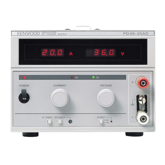
5. CONTROLS AND INDICATORS 5-1. FRONT PANEL CURRENT VOLTAGE POWER V/I CHECK OVP CHECK OUTPUT 10 11 12 Fig. 3 1 POWER switch When turned on, the indicators POWER and either of CC and CV light. The power switch is automatically cut off when protection (overvoltage/ overcurrent/temperature) has operated. - Page 18 7 CC indicator Indicates during constant-current operation. 8 OUTPUT indicator Red LED indicates when the output is on. The preset voltage is available at the output terminals when this indicator is on. 9 OUTPUT switch Output switch (contactless) that turns on and off the output electrically. When the output is on, the OUTPUT indicator 8 lights and the voltage the voltmeter is reading is output at the output terminals and the ammeter reads the current.
-
Page 19: Rear Panel
5-2. REAR PANEL Fig. 4 16 Output terminal (+) output terminals and (±) sensor terminals. 17 Control terminals Terminals for remote control and series/parallel operation. 18 Fan Forced air cooled fan. Keep it apart from walls more than 30 cm. 19 Cap Cap of the fuse holder. -
Page 20: Operation
6. OPERATION 6-1. As a Constant-Voltage Power Supply 1) Check the rated input voltage, then connect the power cord. 2) Turn the voltage adjuster knob (VOLTAGE) fully counter-clockwise. 3) Turn on the power switch. The POWER (red) indicator light and the device is operated. Make sure the OUTPUT switch is off (the indicator is out). -
Page 21: How To Check Voltage And Current
6) Turn on output. Turn on the OUTPUT switch, and the output indicator lights and the power is output through the output terminals. Note : If it is not preferable to apply current suddenly like to a large inductance load, turn the current adjuster knob (CURRENT) fully counterclockwise and increase current gradually after turning on the output. -
Page 22: Application
7. APPLICATION 7-1. Use of Rear-Panel Terminals Rear-panel output control - -S + +S Control terminals ① ② ③ ④ ⑤ ⑥ ⑦ ⑧ ⑨ ⑩ ⑪ ⑫ Fig. 5 The output and control terminals shown above are equipped on the rear panel. These terminals may be used to perform remote sensing, remote control of output voltage and output current, master/slave control operation with power supply connected in series or paralled. -
Page 23: Remote Control Of Constant-Voltage (Resistance, Voltage)
+ × (Note) +S Load - × Two core shield -S Fig. 6 Note : If the load is remote, oscillation might happen due to inductance and capacitance of the output line. In such a case, connect an electrolytic capacitor of some 100μF in parallel with the load as shown above. -
Page 24: Control By Resistance (Ⅰ)
controllers, each unit should be floated independently. 7-3-1. Control by resistance (Ⅰ) It is possible to output voltage which is proportional to resistance. 1) Turn off power. 2) Remove the short bar ①-②. 3) Connect variable resistor R (10k ohms) across 1 and 3 as shown Fig. 7. Note : R must be 10k ohms. - Page 25 × ① ② ③ ④ ⑤ ⑥ ⑦ ⑧ ⑨ ⑩ ⑪ ⑫ Two-core shield Fig. 8 Output voltage ≒ × : Reference voltage (approx. 0 to 10V) Set with the voltage control of the panel. : 0≦R ≦∞ : Constants depending on model. Rated output voltage (kΩ) (kΩ)
-
Page 26: Control By External Voltage
7-3-3. Control by external voltage It is possible to output voltage which is proportional to voltage. 1) Turn off power. 2) Remove the short bar ③-④ and connect external voltage V across ④ and ⑤ as shown Fig. 9. Be very careful about the polarity. ×... -
Page 27: Control By External Voltage
× ① ② ③ ④ ⑤ ⑥ ⑧ ⑩ ⑪ ⑫ ⑦ ⑨ Two-core shield Fig. 10 Imax Output current × R ≒ ≦10kΩ) : Output current [A] : Maximum rated current [kΩ] : External resistance Note : R must be 10k ohms or less (R ≦... -
Page 28: Series/Parallel Connection Operation
(0≦V ≦10V) [A] : Output current [A] : Maximum rated current [V] : External signal voltage Note : The external signal voltage should be 0 to 10V. The input impedance across ⑨ and ⑪ is approximately 10k ohms. Use a two-core shield cable and connect the shield line to ⑪... - Page 29 Connect of control terminals Master ① ② ③ ④ ⑤ ⑥ ⑦ ⑧ ⑨ ⑩ ⑪ ⑫ × Slave ① ② ③ ④ ⑤ ⑥ ⑦ ⑧ ⑨ ⑩ ⑪ ⑫ × Slave ① ② ③ ④ ⑤ ⑥ ⑦ ⑧...
-
Page 30: How To Determine External Resistance R1 And R2
7-5-2. How to determine external resistance R and R [V] : Output voltage of master [V] : Output voltage of slave ① when master’s output voltage is E : Slave ① ’s constants depending on model. Rated output voltage (k Ω ) (k Ω... - Page 31 4) Make connection between each unit and load with a cable of the same length. 5) Ground the GND terminal of the master unit’s panel. (The output connection diagram shows the negative line grounded.) Connect of control terminal Master ① ②...
-
Page 32: Constant-Current Charging/Discharging Of Battery
Note : For connection of the parallel operation with different models, consult agent and our distributor. 7-6. Constant-Current Charging/Discharging of Battery 7-6-1. Constant-current charging It is possible to charge a battery or capacitor automatically with a charging current or a final voltage preset. - Page 33 output of this product is turned on. Note 1 : The DIN connector pins are electrically connected to the positive output terminal. Thus, be sure to use them in the float condition. Note 2 : A 7-pin connector cable for connecting the GP-IB adapter <GP-600B> cannot be connected to the 5-pin connector shown above.
-
Page 34: Optional Accessories
8. OPTIONAL ACCESSORIES 1) Rack mount adapter----------------------------- RK-601 2) GP-IB adapter ------------------------------------ GP-600B 9. MAINTENANCE Replacing Fuse The PD-A power supply unit will not run if the fuse blows out. Some models are supplied with spare fuses, in addition to the fuses built in the units. (Models of rated outputs below 10A) The PD-A power supply unit employs a special fuse filled with anti-arc agent (quartz sand). -
Page 35: Troubleshooting
10. TROUBLESHOOTING Check as noted below if there is anything wrong. If the trouble cannot be correct, call the dealer. Sympton Check Cause Power switch does * Power lamp not lit. * Power cord disconnected or not turn on. connected defectively. *... -
Page 36: Dimensions
11. DIMENSIONS POWER CURRENT VOLTAGE V/I CHECK OVP CHECK OUTPUT Fig. 17... - Page 37 Fig. 18 Model PD18-20AD PD18-30AD PD36-20AD (mm) (including power input connecter)
- Page 38 Fig. 19 PD18 PD36 PD56 PD56 PD110 PD110 Model -10AD -10AD -6AD -10AD -3AD -5AD (mm) (including power input connecter)
- Page 39 7F Towa Fudosan Shin Yokohama Bldg. 2-18-13, Shin Yokohama, Kohoku-ku,Yokohama, Kanagawa, 222-0033 Japan http://www.texio.co.jp/...
Need help?
Do you have a question about the PD18-10AD and is the answer not in the manual?
Questions and answers