
Subscribe to Our Youtube Channel
Related Manuals for TEXIO PSF-400H


Summary of Contents for TEXIO PSF-400H
- Page 1 INSTRUCTION MANUAL REGULATED DC POWER SUPPLY PSF SERIES PSF-400H PSF-800H ©PRINTED IN JAPAN B68-0166-00...
- Page 2 ■ About Brands and Trademarks Our company and product names described in this manual are the brands and trademarks owned by the respective companies or organizations in each country and region. ■ About the Instruction Manual Permission from the copyright holder is needed to reprint the contents of this manual, in whole or in part.
-
Page 3: Table Of Contents
CONTENTS USING THE PRODUCT SAFELY ..............Ⅰ-Ⅳ 1. GENERAL ____________________________________________ 1 1-1. General ..................... 1 1-2. Applicable Products ................1 1-3. Features.................... 1 1-4. Accessories..................3 2. SPECIFICATIONS______________________________________ 4 3 PRELIMINARY INSTRUCTIONS __________________________ 11 4. DEVICES ON PANELS _________________________________ 13 4-1. - Page 4 5-5-2. OVP/OCP function (02) ..............30 5-5-3. OFF timer function (03) ..............31 5-5-4. Sequence function (04) ..............32 5-5-5. External control (external voltage, external resistance) (05) .... 35 5-5-6. External control (ON/OFF) (06) ............37 5-5-7. Master-slave function (10)..............38 5-6.
- Page 5 8-7-3. Using the RS-232C interface ............62 8-7-4. Using the local bus................62 8-8. Communication commands ............62 8-8-1. Output voltage setting (:VOLT) ............64 8-8-2. OVP setting (:VOLT:PROT) ............64 8-8-3. Output current setting (:CURR) ............64 8-8-4. OCP setting (:CURR:PROT)............65 8-8-5.
- Page 6 8-8-31. Wait for completion (*WAI) ............73 8-8-32. Local address setting (:ADDR)............73 8-8-33. Remote/local setting (:REMOTE) ........... 74 8-9. Registers..................75 8-9-1. Status register (STB、SRE) .............. 76 8-9-2. Event register (ESR、ESE)............... 77 8-9-3. Function of the status byte ............... 78 8-9-4.
-
Page 7: Using The Product Safely
USING THE PRODUCT SAFELY ■ Preface To use the product safely, read this instruction manual to the end. Make sure you understand how to correctly use this product before using it. If you read this manual but you do not understand how to use the product, call our company or one of our service centers. - Page 8 USING THE PRODUCT SAFELY ■ Do not remove the product's covers and panels Never remove the product's covers and panels for any purpose. Doing so may expose the user to electric shock, or result in a fire. ■ Caution on using the product The warning items below are given to avoid danger to the user's body and life, and to prevent the damage and deterioration of the product.
- Page 9 USING THE PRODUCT SAFELY ■ Warning about grounding If the product is equipped with a GND terminal on the front or rear panel, be sure to connect a ground wire to the GND terminal to ensure safe operation. ■ Warning about installation conditions ●...
-
Page 10: Daily Maintenance
USING THE PRODUCT SAFELY ■ Input/output Terminal Maximum input to the input terminals is specified to prevent the product from being damaged. Do not supply input, exceeding the specifications that are indicated in the "SPECIFICATIONS" section of this manual. Also, do not supply power to the output terminals from the outside. -
Page 11: General
It is possible to control the PSF Series from a Personal computer through the optional GP-IB, RS-232C or USB interface board. The application software exclusive for the PSF series may be downloaded from our homepage. Homepage address – http://www.texio.jp 1-2. Applicable Products Product name Voltage range... - Page 12 A built-in power factor correction circuit ensures compatibility to a wide AC input voltage range from AC100V to 240V without the need of switching. It also suppresses harmonic current. ● Rotary Panel Operation Unit The panel operation unit may be rotated by 90 degrees for easy-to-see monitoring in either horizontal or vertical installation.
-
Page 13: Accessories
● Options Two types of optional boards, GP-IB + local bus board and RS-232C + USB + local bus board, are available for applications with several built-in units, which are operated simultaneously in a factory, etc. It is possible to store sequence programs and read voltage and current data if application software is created. -
Page 14: Specifications
2. SPECIFICATIONS ● Output Specifications Model PSF-400H PSF-800H Rated output voltage 800.0V Setting accuracy 0.1%setting±2digit (23°C±5°C) Resolution 100mV Display accuracy 0.2%reading±2digit (23°C±5°C) ※ 1 Rated output current 3.00A 6.00A Setting accuracy 0.2%setting±2digit (23°C±5°C) Resolution 10mA Display accuracy 0.3%reading±2digit (23°C±5°C) ※ 2... - Page 15 ● Constant-Current Characteristics PSF-400H PSF-800H of rated current Source fluctuation ※5 0.05%±10mA of rated current Load fluctuation ※13 0.05%±15mA Ripple noise (rms) 15mA 20mA after 30-minute warming up ※12 Temperature coefficient (typ.) ±200ppm/°C( ● Constant-Power Characteristics PSF-400H PSF-800H ※ 5 Source fluctuation 0.5%±10W...
-
Page 16: Protective Functions
● Functions Constant-voltage (CV) Output voltage: Approx. 0V to 800V control with external voltage for external voltage: 0V to 10V Constant-voltage (CC) control Output voltage: Approx. 0V to 800V with external resistance for external resistance: 0Ω to 10KΩ Constant-current (CC) control Output current: Approx. -
Page 17: Environmental Conditions
Power In terminals - output terminals: AC2300V, 1min. Power In terminals - frame: DC500V, 30MΩor more Power In terminals - output terminals: Insulation resistance DC1000V, 30MΩor more Output terminals - frame: DC1000V, 30MΩor more Outside dimensions 124(H)mm×210(W)mm×290mm(D) (Projections not included.) Weight PSF-400H: Approx. 5kg PSF-800H: Approx. 6kg... - Page 18 ● One-Control Operation Setting Table PSF-400H Single Parallel connection Item 400H 400H×2 400W 800W Voltage setting SLOW 100mV FAST Range 0V to 820V Min. display digit 100mV Current setting SLOW 10mA 100mA FAST Range 0A to 3.07A 0A to 6.1A Min.
- Page 19 PSF-800H Single parallel connection Item 800H 800H×2 800W 1600W SLOW 100mV FAST Voltage setting Range 0V to 820V Min. display digit 100mV SLOW 10mA 100mA FAST Current setting Range 0A to 6.15A 0A to 12.3A Min. display digit 10mA 100mA SLOW FAST 100W...
- Page 20 ● Default Setting and Storage after Power Off Default Setting List of PSF Series Storage after Item Initial setting(400H/800H) power off Voltage 0.0V ○ Current 0.00A ○ Power 410W/820W ○ 840.0V ○ 3.15A/6.30A ○ Display mode ○ Menu display Initialized when power is turned off. ×...
-
Page 21: Preliminary Instructions
3 PRELIMINARY INSTRUCTIONS Be sure to read through this section before using the PSF Series power supply unit. ● Checking the Source Voltage Use the PSF Series power supply unit within the rated source voltage range, which is AC100V to 240V (allowance: ±10%),single-phase, 50Hz or 60Hz. - Page 22 ● Instruction on Using the Output Terminals The PSF Series is a floating type power supply unit. Connect either output terminal on the rear panel with the GND terminal of the frame, if output should be grounded. The output terminals on the front panel are auxiliary output terminals, whose maximum current is 3A(400H) or 6A(800H).
-
Page 23: Devices On Panels
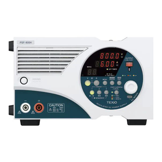
4. DEVICES ON PANELS 4-1. Front Panel Fig4-1 Front Panel(PSF-800H) 1. POWER ON/OFF switch Press the switch to the (I) position to turn on the power supply unit. Press it again to turn off the unit (the switch returns to the Out position). 2. -
Page 24: Operation Panel
4-2. Operation Panel Fig 4-2 Operation Panel(PSF-800H) 5. Address No., number of steps, number of cycles, and menu No. Normal operation Sequence operation Menu Number of steps is Not displayed. Menu No. is displayed. displayed. 6. Current 7-segment LED Normal operation Sequence operation Menu Alarm... - Page 25 8. ESC/DISP key Changes the channel display, sequence operation display (i.e., step No. and cycle No.), remaining time in off-timer operation and other displays. When the menu is displayed, pressing it exits the function selection mode and returns to the normal mode. 9.
- Page 26 17. PRESET 2 key (green) Reads out data stored in PRESET 2. Serves as a jump key to a number one smaller than the step number in the sequence mode. 18. PRESET 1 key (green) Reads out data stored in PRESET 1. Serves as a start/pause key in the sequence mode.
-
Page 27: Rear Panel
4-3. Rear Panel Fig 4-3 Rear Panel(PSF-800H) 21. Optional board slot Used to install the optional IF60-GP or IF60-RU board for controls through the interface. The product is supplied with slot covered with a blank panel. 22. J3 external control connector Used for various controls. - Page 28 Pin No. Signal name Function COM. Connected with the negative output terminal. Causes the alarm status when short-circuited with the EXT ALARM IN COM pin. EXT OUTPUT IN Turns on output when short-circuited with the COM pin. COM. Connected with the negative output terminal. Open collector output.
- Page 29 Output ground terminal Used to ground the positive or negative output terminal of this unit. An output ground cable should be used to ground the output terminal. 29. AC INPUT Connect the AC power cable supplied with the unit with this plug receptacle and supply commercial power to the unit.
-
Page 30: Operation Procedures
5. OPERATION PROCEDURES 5-1. Connecting AC Power Cable ・ Make sure that the power source is shut off. ・ Use the AC power cable supplied with the product. ・ Plug the connector of the AC power cable into the AC INPUT receptacle on the rear panel. - Page 31 Fig 5-1Connection with Rear Output Terminals The negative potential of the external voltage control is the same as that of the negative output terminal. If the power supply unit is grounded at the positive terminal and the power source for external control is grounded at the negative terminal, the load cables for external voltage control short-circuits the output of the power supply unit, resulting in troubles.
-
Page 32: Assembling And Connecting The Front Output Terminal Plug
5-2-2. Assembling and connecting the front output terminal plug The cable (load line) and 1.5 mm wrench are not supplied. Fig 5-3 Assembly diagram of the front output terminal plug Insert the cable (load line) into the plug. Use a 1.5 mm wrench to fasten the 2 screws. Insert the cover into the plug and make sure it hooks into place (completion image). -
Page 33: Operation Ranges
・ Voltage setting range : 0V to 800V (All models) ・ Current setting range : 0A to 3A (PSF-400H) : 0A to 6A (PSF-800H) ・ Power setting range : 10W to 400W (PSF-400H) -
Page 34: Various Setting
5-4. Various Setting 5-4-1. How to rotate display panel by 90 degrees The panel operation unit of the PSF-H Series may be rotated by 90 degrees to ensure easy operation in either horizontal or vertical installation. Operation procedure while pressing the ROTATE key OUTPUT *ON/・OFF Hold the encoder the panel operation unit. -
Page 35: How To Set Voltage
5-4-3. How to set voltage Operation procedure Press the V key, which is then lit in green. If not, press the V key to turn it on. Set an intended value with the encoder. 5-4-4. How to set current Operation procedure Press the A key, which is then lit in green. -
Page 36: How To Output
5-4-6. How to output The following output methods are available: 1. Turning output on or off using the OUTPUT key. Press the OUTPUT key to turn output on or off. Output is on while this key is lit. 2. Turning output on or off using the external control function. 5-5-6. -
Page 37: How To Display The Set Value In Outputting Condition
5-4-7. How to display the set value in outputting condition The power supply unit displays the output value in the outputting condition. Press the ENTER/CHECK key in this condition to change the displayed output value into the set value. Operation procedure When output value display is OUTPUT Every press of the... -
Page 38: Various Functions Available On Menus
5-5. Various Functions Available on Menus Introduction: ・ Every press of the MENU key changes the menu numbers. ・ MENU options are available from “01” to “06”. ・ Press the ESC/DISP key to return from the NEMU setting condition to the normal condition. -
Page 39: Preset Function (01)
Table 5-1 Set function Functions that cannot be set or used simultaneously Preset Sequence External(voltage/resistance) OVP/OCP Off timer Sequence Delay External (ON/OFF) Preset Off timer Sequence External (voltage/resistance) External (ON/OFF) Delay Tracking External Preset (voltage/resistance) External (On/Off) Off timer 5-5-1. Preset function (01) This function stores intended set values in advance. -
Page 40: Ovp/Ocp Function (02)
5-5-2. OVP/OCP function (02) ● OVP: (Over Voltage Protection) The OVP function turns off output when the output voltage of the PSF Series exceeds the preset OVP value. The setting range is from 10.0V to 840.0V. The resolution is 1V. ●... -
Page 41: Off Timer Function (03)
5-5-3. OFF timer function (03) This function deactivates output of the power supply unit automatically. It is possible to set the timer-off period in units of ten minutes. Operation procedure Press the MENU key until menu number “03” is displayed. Press the ENTER/CHECK key to enter the OFF timer setting mode. -
Page 42: Sequence Function (04)
This function executes sequence programs, which are written in the PSF Series power supply unit using the optional interface board in advance, without anything else. Access the Texio homepage or consult its distributor for the procedures of writing sequence programs. The application software exclusive for sequence operation may be downloaded from our homepage. - Page 43 Operation procedure How to set an intended end step number. Then, set an intended end step number with the encoder. The setting range is from 0 to 99. Press the ENTER/CHECK key to validate it. Set the number of times of How to set the number of times of repeating the steps with the repeating.
- Page 44 The method of writing the sequence programs is described in the application software exclusive for sequence operation. The following shows an example of the sequence program and the screen of the exclusive application. Note that it is impossible to rewrite the sequence programs on the PSF Series power supply unit.
-
Page 45: External Control (External Voltage, External Resistance) (05)
This function allows the user to control the current of the PSF Series power supply unit by connecting an external resistance with the unit. The output current is controlled from approximately 0A to approximately 3A(PSF-400H) or approximately 6A(PSF-800H) output current when 0Ω to 10kΩis connected with the power supply unit. ◆ See Sections “5-7-2. - Page 46 Operation procedure Press the MENU key until menu number “05” is displayed. Press the ENTER/CHECK key to enter theexternal control setting mode. Set the intended control external voltage or external resistance with the encoder. (The external control is set to OFF before shipment.) Press the ENTER/CHECK key to validate it.
-
Page 47: External Control (On/Off) (06)
5-5-6. External control (ON/OFF) (06) It is possible to turn on or off the output by shorting or opening the signal pins with external contact signals. Short circuit: OUTPUT ON, Open: OUTPUT OFF See Section below. “5-7-4. Output ON/OFF with external contacts” ◆... -
Page 48: Master-Slave Function (10)
5-5-7. Master-slave function (10) No panel operations are enabled on the slave units. Besides, the Off Timer, sequence and external control functions of the slave units are initialized. On slave units in parallel connection, “----“ is displayed and the monitor value is not displayed. -
Page 49: Output Voltage Remote Sensing
5-6. Output Voltage Remote Sensing The PSF Series power supply unit has an output voltage remote sensing function. It eliminates influences of voltage drop between the power supply unit and load, which is caused by the contact resistance or the resistance of the load cable conductors. -
Page 50: External Control Functions
5-7. External Control Functions This section describes how to assemble the external control connector. Remove the contact for the external control connector (XG5M-2635-N: OMRON manufacture) supplied with the unit. Use a dedicated tool (XY2E-0001: OMRON manufacture) to remove the contact. Or, use a pointed stick to gently push down the prong and pull it out, making it easy to remove the contact. -
Page 51: Output Voltage Monitor And Output Current Monitor
5-7-1. Output voltage monitor and output current monitor It is possible to monitor the output voltage and output current of the PSF-H Series power supply unit in voltage. The internal impedance of the voltage and current monitoring circuits is approximately 1kΩ. Be careful not to flow current over 1mA through the monitoring circuits. -
Page 52: Set Voltage With External Voltage Or Resistance
5-7-2. Set voltage with external voltage or resistance It is possible to control the output voltage by external voltage or external resistance through the connector J3 (EXT CONT) on the rear panel if external control is selected in Section “5-5-5. External control (external voltage, external resistance) (05)”... -
Page 53: Set Current With External Voltage Or Resistance
5-7-3. Set current with external voltage or resistance It is possible to control the output current by external voltage or external resistance through the connector J3 (EXT CONT) on the rear panel if external control is selected in Section “5-5-5. External control (external voltage, external resistance) (05)”... -
Page 54: Output On/Off With External Contacts
5-7-4. Output ON/OFF with external contacts It is possible to turn on or off output with external contacts if the external control function is activated in Section “5-5-6. External control (ON/OFF) (06)” below. ◆ For the setting procedures, see Section “5-5-6. -
Page 55: Various Status Signals (Cv, Cc & Alarm)
5-7-6. Various status signals (CV, CC & ALARM) It is possible to check the status using the open collector output. ● Constant-voltage (CV) status signal This status signal goes Low when the PSF-H Series power supply unit enters the constant-voltage (CV) status. ●... -
Page 56: Activating Output When Turning On Power
Fig. 5-15 Photo coupler current 5-8. Activating output when turning on power Using the output on/off function with the external contacts shown in Section “5-7-4. Output ON/OFF with external contacts” it is possible to turn on output automatically as soon as power is input to the power supply unit. The value stored automatically when the source voltage is cut off or the POWER switch is shut off is output. - Page 57 The OUTPUT key does not start sequence operation. Use the PRESET 1 key ( ) to start sequence operation. Even if the sequence function is activated and the SEQUENCE の LED is lit, the sequence operation will not start unless the PRESET 1 key ( ) is pressed.
-
Page 58: Other Functions
6 OTHER FUNCTIONS 6-1. Display in alarm status When the PSF Series power supply unit enters the alarm status or the function described in Section ”5-7-5. Alarm function using external contacts” is used, the alarm code shown below is displayed, indicating that an alarm occurs in the power supply unit. -
Page 59: One-Control Parallel Operation
6-2. One-Control Parallel Operation The PSF Series power supply units are capable of one-control parallel operation of up to two units, including the master unit. When executing one-control parallel operation using master units, the master and slave units should be set properly in advance. ◆... - Page 60 OP-22P Master unit Slave unit 1 ー Load + + grounding - grounding Fig. 6-1 Parallel Connection...
- Page 61 6-2-1. Master-slave connection using joint kits The joint kits faclilitate master-slave connection of two units and offer sufficient rigidity. How to Connect Units Vertically (1) Remove the rubber shoes from the bottom of unit A. (Keep the removed rubber shoes and screws with care not to lose them.) (2) Fix the joint kit (JK-10) to the top panel of the unit B with the flat countersunk head screws supplied with the kit.
- Page 62 How to Connect Units Horizontally (1) Remove the rubber shoes from the bottom of unit A. (Keep the removed rubber shoes and screws with care not to lose them.) (2) Fix the joint kit (JK-10) to the side with no rubber shoes of the unit B with the flat countersunk head screws supplied with the kit.
-
Page 63: Accessories
7 OPTION 7-1. Accessories The options shown below are available for the PSF Series power supply unit. JK-10 Joint kit HK-10 Handle kit OP-22P Parallel signal cable 7-2. Interface Boards Two types of optional interface boards shown below are available: (1) IF-60GP:GP-IB+local bus (2) IF-60RU:USB+RS-232C+local bus... -
Page 64: External Control Throught Interface Board
8 EXTERNAL CONTROL THROUGHT INTERFACE BOARD 8-1. Remote control It is possible to control the PSF Series power supply unit from a Personal computer or sequencer through communication when the optional interface board is mounted in it. Two types of interface boards IF-60GP and IF-60RU are available for communication with a Personal computer through GP-IB, RS-232C and USB interfaces. -
Page 65: Specifications
8-3. Specifications 8-3-1. Specifications of IF-60RU RS-232C section Specifications Conforms to the RS-232C Standards. Data transmission speed 57600[bps] Data bit Data: 8 [bits], stop bit: 1 [bit], parity: none Max. cable length 10[m] Connector type D-sub, 9-pin, plug Applicable cable Mass-marketed interlink cable (Socket 9-pin to socket 9-pin) Q’ty of connectable units One-to-one connection only... -
Page 66: Specifications Of If-60Gp
8-3-2. Specifications of IF-60GP GP-IB section Specifications Conforms to IEEE488-1978. Interface functions SH1, AH1, T6, L4, SR1, RL1, PR0, DC1, DT0, C0, & E1 Address setting Address between 1 and 30 may be set freely. Delimiter LF, EOI, & LF + EOI Listener function Output conditions of controlled power supply units may be set. -
Page 67: Connection Methods
8-4. Connection Methods Refer to the instruction manual supplied with the interface boards for the mounting method in the PSF-H Series power supply units. Be sure to confirm that power is off before mounting the interface board for safe operation. The following shows an example of connecting several PSF-H Series power supply units through the local buses. -
Page 68: Connection Cable
8-5. Connection cable ・ Use the exclusive modular cables for local bus connection. (Our product Nos.:CB-0603S,CB-0615S,CB-0630S & CB-06100S) ・ Use GP-IB cables obtainable on the market for GP-IB connection. (Our product No.: CB-2420P) ・ Use USB cables (applicable to the full speed or superior) obtainable on the market for USB connection. - Page 69 Set the system address and/or Personal computer address Operation procedure Turn on the unit while holding the A key. “Sy.Ad” is displayed on the voltage 7-segment LED, and the address is displayed on the current 7-segment LED. Keep the A key depressed until “Sy.Ad”...
- Page 70 Use the IF-60RU in the master unit when the USB interface is used. Fig. 8-3 Address Setting Example using GP-IB Interface...
-
Page 71: Using Interface Boards
・ The USB hub is easily affected by external noises, which may cause malfunctioning. Utilize self-powered operation as far as possible so that the communication path is not affected by noises. ※ : You may download the instruction manual of the API from the Texio homepage. Access to: http://www.texio.jp... -
Page 72: Using The Rs-232C Interface
8-7-3. Using the RS-232C interface You may use the serial port of your Personal computer or sequencer for communication through the RS-232C interface. The RS-232C interface utilizes the CTS-RTS flow for communication control. If the flow control fails to work properly, some characters may be lost, resulting in malfunctioning. -
Page 73: Command List
Command list Category Set item Command Query Page Function Output voltage setting :VOLT :VOLT? OVP setting :VOLT:PROT :VOLT:PROT? Output Output current setting :CURR :CURR? setting OCP setting :CURR:PROT :CURR:PROT? Output power setting :POW :POW? Output ON/OFF :OUTP :OUTP? Function Display switch :CONF:DISP :CONF:DISP?... -
Page 74: Output Voltage Setting (:Volt)
This command sets or inquires about the output current. Setting :CURR <value> The <value> range in single-unit operation is as shown below: 0.00 to 3.07 PSF-400H 0.00 to 6.15 PSF-800H Two decimal places are valid. The setting range changes in power extension master-slave (parallel) operation. -
Page 75: Ocp Setting (:Curr:prot)
This command sets or inquires about the OCP (over-current protection) value. Setting :CURR:PROT<value> The <value> range in single-unit operation is as shown below: 0.10 to 3.15 PSF-400H 0.10 to 6.30 PSF-800H Two decimal places are valid. The setting range changes in power extension master-slave (parallel) operation. -
Page 76: Output On/Off (:Outp)
8-8-6. OUTPUT ON/OFF (:OUTP) This command turns on or off output. Setting :OUTP <value> <value> and On/Off is as shown below: Application example :OUTP 1 Activates output. Query :OUTP? Response example Indicates that output is activated. “?” has the same function as <value> Remark This command causes an execution error if output is to be set externally. -
Page 77: External Output Voltage Controlon/Off (:Ext:volt)
8-8-9. External output voltage controlON/OFF (:EXT:VOLT) This command select the external output voltage control mode. Setting :EXT:VOLT <value> <value> is as shown below: 0: Deactivates external output voltage control. (for control from the panel or through communication) 1: Actives external output voltage control. Application example :EXT:VOLT 1 Selects the exterenal output voltage control. -
Page 78: Off Timer On/Off (:Timer:mod)
8-8-12. Off timer ON/OFF (:TIMER:MOD) This command activates or deactivates the Off Timer. Setting :TIMER:MOD <value> <<value> is as shown below: 0: Deactivates the Off Timer. 1: Activates the Off Timer. Application example :TIMER:MOD 1 Activates the Off Timer. Query :TIMER:MOD? Inquires about the setting. -
Page 79: Preset Calling (:Pres:call)
8-8-15. Preset calling (:PRES:CALL) This command calls and inquires about preset data. Setting :PRES:CALL <value> <value> is as shown below: 0: Cancels preset. 1: Calls PRESET 1 data. 2: Calls PRESET 2 data. 3: Calls PRESET 3 data. Application example :PRES:CALL1 Calls the set values stored in PRESET 1. -
Page 80: Sequence Jump Setting (:Seq:step)
8-8-18. Sequence jump setting (:SEQ:STEP) This command jumps to a specified step of sequence operation. Setting :SEQ:STEP <value> < The <value> range is from 0 to 99. This command is accepted in the wait-for-sequence status (PAUSE) only. Application example :SEQ:STEP 2 Changes the sequence step No. -
Page 81: Sequence Repletion Frequency Setting (:Seq:cycl)
This command inquires about the model. Setting None. Query only. Query *IDN? The brand name, model name, serial number and version are returned in this order. Response example TEXIO,PSF-400H,0,1.00/V1.00 The serial number is fixed to 0. The version data include the hardware and software versions. -
Page 82: Event Register Inquiry (*Esr?)
8-8-24. Event register inquiry (*ESR?) The function of this command is described in “Event register” in the following section. 8-8-25. Event enable register setting(*ESE) The function of this command is described in “Event register” in the following section. 8-8-26. Status byte inquiry (*STB?) The function of this command is described in “Status register”... -
Page 83: Command Completion (*Opc)
8-8-30. Command completion (*OPC) This command notifies of command execution. *OPC Setting Bits 0 of the event status registers are set when the command is executed. SRQ is generated depending on the status of the ESE register and SRE register. *OPC? Query The value “1”... -
Page 84: Remote/Local Setting (:Remote)
8-8-33. Remote/local setting (:REMOTE) This command sets or inquires about the remote/local status. Setting :REMOTE<value> <value> is as shown below: 0: Local status (Normal manual operation) 1: Remote status 2: Local lockout remote status (Cannot return to the local status through key operation.) Application example :REMOTE0... -
Page 85: Registers
8-9. Registers The PSF power supply unit has registers that conform to the status reporting specified in IEEE488.2. -
Page 86: Status Register (Stb、Sre)
8-9-1. Status register (STB、SRE) Initial STB value Initial SRE value Data Item Description Unused. Service request Message summary Standard event summary Output message available Unused. Unused. Local bus error LERR Local bus Time out Each bit is masked when “0” is set in it. (It is the default setting.) Masking is canceled when “1”... -
Page 87: Event Register (Esr、Ese)
Reads out the status byte and MSS *STB? Setting command None. Query only. Query command *STB? Response example The bits set with the *SRE command are only returned in decimal. The status byte register is not cleared even if an inquiry is made using this command. -
Page 88: Function Of The Status Byte
8-9-3. Function of the status byte If some event occurs and some bit of the status byte is set to 1, bit 6 is set to 1 and a service request (SRQ) is issued. Four status bits shown below may possibly be the causes of an SRQ in the PSF Series power supply unit. -
Page 89: Clear And Reset Statuses
8-9-5. Clear and reset statuses It is possible to cause clearing or resetting in the PSF Series power supply unit by issuing commands or executing specific operations. IFC (Interface clear) Responses to the universal command IFC are as shown below: ・... -
Page 90: Remote/Local Function
8-9-6. Remote/local function The remote/local function is controlled by the system controller and with the FAST key of the PSF Series power supply unit. (This key serves as the FAST, LOCK and LOCAL keys.) The PSF Series power supply unit always resides in the local, remote, or remote with local lockout status. -
Page 91: Troubleshooting
9 TROUBLESHOOTING This section shows the typical phenomena that imply troubles. Some phenomena may be solved by rechecking or in simple manner. Contact the nearest our distributor for phenomena that rechecking or countermeasures may not eliminate or improve. Never detach the case to check the inside. Phenomenon Possible cause Check &... -
Page 92: Maintenance
10 MAINTENANCE The PSF Series power supply unit employs a fan for forced cooling. Clean the dust filter inside the front grill periodically to maintain the cooling efficiency. Pull the front grill while pressing the notch in the upper part to detach the grill. -
Page 93: Outside Dimensions
11 OUTSIDE DIMENSIONS 12.5 ※ The handle is available by option Fig. 10-2 Outside Demension of PSF-H... - Page 94 1850-1, Tsuruma, Machida-shi, Tokyo, 194-0004, Japan http://www.texio.jp/...
Need help?
Do you have a question about the PSF-400H and is the answer not in the manual?
Questions and answers