Table of Contents
Advertisement
Quick Links
PW-A SERIES MULTI-OUTPUT DC STABILIZED
POWER SUPPLY UNITS
PW-A SERIES
PW8-3AQP
PW16-2ATP
PW18-1.8AQ PW18-2ATP
PW18-3ADP
PW36-1.5AD PW36-1.5ADP
OPTIONAL INTERFACE UNITS FOR
IF-41RS
© PRINTED IN JAPAN
INSTRUCTION MANUAL
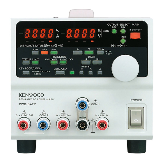
PW8-3ATP
PW16-5ADP
PW24-1.5AQ PW26-1AT(S)
PW-A SERIES
IF-41GU
B68-0014-00
PW8-5ADPS
PW18-1.3AT(S)
PW18-3AD
IF-41USB
Advertisement
Table of Contents


Need help?
Do you have a question about the PW8-3AQP and is the answer not in the manual?
Questions and answers