Table of Contents
Advertisement
Quick Links
Advertisement
Table of Contents

Related Manuals for TEXIO PSW Series


Summary of Contents for TEXIO PSW Series
- Page 1 INSTRUCTION MANUAL MULTI RANGE DC POWER SUPPLY PSW SERIES PSW-360L30 PSW-720L30 PSW-1080L30 PSW-360L80 PSW-720L80 PSW-1080L80 PSW-360M160 PSW-720M160 PSW-1080M160 PSW-360M250 PSW-720M250 PSW-1080M250 PSW-360H800 PSW-720H800 PSW-1080H800 B71-0441-11...
- Page 2 ■ About Brands and Trademarks “TEXIO” is the product brand name of our industrial electronic devices. All company names and product names mentioned in this manual are the trademark or the registered trademark of each company or group in each country and region.
-
Page 3: Table Of Contents
CONTENTS USING THE PRODUCT SAFELY ·········································· Ⅰ -Ⅳ 1 GETTING STARTED ............. 1 1-1. PSW Series Overview ............1 1-1-1. Series lineup ..................1 1-1-2. Main Features ..................2 1-1-3. Accessories ..................2 1-2. Appearance ................4 1-2-1. PSW Front Panel ................4 1-2-2. - Page 4 2-4. Test Script ................47 2-4-1. Filename of TestScript ..............47 2-4-2. Test Script Settings ................. 47 2-4-3. Setting the Test Script ..............48 2-4-4. Load Test Script from USB drive ............ 49 2-4-5. Run Test Script ................. 49 2-4-6. Run Test Script (At Startup) ............50 2-4-7.
- Page 5 8 APPENDIX ................89 8-1. PSW Default Settings ............89 8-2. Error Messages & Messages ..........91 8-3. LCD Display Format............. 91 9 Specifications ..............92 9-1. PSW 360W Type I ..............92 9-2. PSW 720W Type II ..............95 9-3.
- Page 6 USING THE PRODUCT SAFELY ■ Preface To use the product safely, read instruction manual to the end. Before using this product, understand how to correctly use it. If you read the manuals but you do not understand how to use it, ask us or your local dealer. After you read the manuals, save it so that you can read it anytime as required.
- Page 7 USING THE PRODUCT SAFELY WARNING CAUTION ■ Do not remove the product's covers and panels Never remove the product's covers and panels for any purpose. Otherwise, the user's electric shock or fire may be incurred. ■ Warning on using the product Warning items given below are to avoid danger to user's body and life and avoid the damage or deterioration of the product.
- Page 8 USING THE PRODUCT SAFELY ■ Warning item on Grounding If the product has the GND terminal on the front or rear panel surface, be sure to ground the product to safely use it. ■ Warnings on Installation environment ● Operating temperature and humidity Use the product within the operating temperature indicated in the “rating”...
- Page 9 USING THE PRODUCT SAFELY ■ Input / Output terminals Maximum input to terminal is specified to prevent the product from being damaged. Do not supply input, exceeding the specifications that are indicated in the "Rating" column in the instruction manual of the product. Also, do not supply power to the output terminals from the outside.
-
Page 10: Using The Product Safely
1-1. PSW Series Overview 1-1-1. Series lineup The PSW series consists of 9 models, divided into 3 different model types covering 3 power capacities: Type I(360W), Type II(720W) and Type III(1080 W). Model name... -
Page 11: Main Features
1-1-2. Main Features ・High performance/power. Performance ・Power efficient switching type power supply. ・Low impact on load devices. ・Fast transient recovery time of 1ms. ・Fast output response time. ・OVP, OCP and OTP/OHP protection. Features ・Adjustable voltage and current slew rates. ・User adjustable bleeder control to quickly dissipate the power after shutdown to safe levels. - Page 12 PSW-008 Basic Accessory Kit: (250,800 volt models) Air filter x1 Analog control protection dummy x1 Analog control lock level x1 Option Part number Description GET-001 Extended terminal(30,80,160 volt models) GET-002 Extended terminal(250,800 volt models) PSW-001 Accessory Kit: Pin contact x 10、Socket x 1 Protection cover x 1 (Compatible with OMRON XG5M-2635-N) PSW-005...
-
Page 13: Appearance
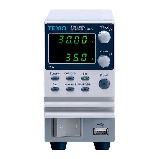
1-2. Appearance 1-2-1. PSW Front Panel PSW-720**** (720W:TypeII) Voltage Multi- Range DC Power Supply Voltage 720W Display knob Current Current knob Cover panel Output Function OVP/ OCP Output Test Lock/ Local PWR DSPL Power Function switch keys USB A port PSW-1080**** (1080W:TypeIII) PSW-360****(360W:TypeI) Voltage... - Page 14 Sets the current and voltage limits. Test Test Used to run customized scripts for testing. Lock/Local Lock/Local Locks or unlocks the panel keys to prevent accidentally changing panel settings. PWR DSPL PWR DSPL Toggles the display from viewing V/A →V/W→V/A Press the Current knob to switch the display from V/W to W/A.
-
Page 15: Rear Panel
1-2-2. Rear Panel PSW-720M160, PSW-720L80, PSW-720L30 (720W) Analog control Sense+ USB B Output connector terminal Port terminal(+) Sense- terminal SER.NO. LABEL Output terminal(-) 240V 47 63Hz 1000VA MAX. AC Input PSW-1080M160, PSW-1080L80, PSW-1080L30 PSW-360M160, PSW-360L80, (1080W) PSW-360L30 (360W) AC Input SER.NO. - Page 16 PSW-720H800, PSW-720M250 (720W) Sense+ USB B Output Analog control terminal port terminals +V connector Sense- terminal SN.C. S SER.NO. LABEL Chassis ground Output terminals -V 240V 47 63Hz 1000VA MAX. AC Input PSW-1080H800, PSW-1080H250,(1080W) PSW-360H800 PSW-360M250 (360W) AC Input SN.C. S SER.NO.
- Page 17 Standard 26 pin MIL connector Analog Control (OMRON XG4C Plug). Connector The analog control connector is used to monitor current and voltage output, machine status (OVP, OCP, OTP/OHP etc.), and for analog control of the current and voltage output. Use an OMRON XG5M socket as the mating socket.
-
Page 18: Theory Of Operation
Line Voltage Type III:PSW-1080L30/L80/M160/M250/H800 ・Voltage Input: 100~240 VAC Input (Type III) ・Line frequency: 50Hz/60Hz (automatically switchable) 1-3. Theory of Operation The theory of operation chapter describes the basic principles of operation, protection modes and important considerations that must be taken into account before use. - Page 19 PSW 30V Series Operating Area Type I Type II Type III Po… 0 20 Current(A) Cur… PSW 80V Series Operating Area 9.0 13.5 40.5 Type I Type II Type III 26.6 Po… 0 20 Current(A) Cur… PSW 160V Series Operating Area 2.25 4.5 6.75 14.4 21.6...
-
Page 20: Cc And Cv Mode
PSW 250V Series Operating Area 1.44 2.88 4.32 13.5 Type I Type II Type III Po… 0 20 Current (A) Cur… PSW 800V Series Operating Area 0.45 0.9 1.35 1.44 2.88 4.32 Type I Type II Type III Po… 0 20 Current (A) Cur…... -
Page 21: Slew Rate
the critical resistance (R ). The critical resistance is determined by V . The power supply will operate in CV mode when the load resistance is greater than the critical resistance. This means that the voltage output will be equal to the V voltage but the current will be less than I . -
Page 22: Bleeder Control
Slew rate: Disabled Slew rate:Enabled 1-3-4. Bleeder Control Background The PSW DC power supplies employ a bleed resistor in parallel with the output terminals. Bleed Load resistor Bleed resistors are designed to dissipate the power from the power supply filter capacitors when power is turned off and the load is disconnected. -
Page 23: Internal Resistance
1-3-5. Internal Resistance Background On the PSW, the internal resistance of the power supply can be user-defined in software. (Internal Resistance Setting, page 57). When the internal resistance is set it can be seen as a resistance in series with the positive output terminal. -
Page 24: Considerations
1-3-7. Considerations The following situations should be taken into consideration when using the power supply. Inrush current When the power supply switch is first turned on, an inrush current is generated. Ensure there is enough power available for the power supply when first turned on, especially if a number of units are turned on at the same time. - Page 25 Reverse Current: When the power supply is connected to a regenerative load Regenerative load such as a transformer or inverter, reverse current will feed back to the power supply. The PSW power supply cannot absorb reverse current. For loads that create reverse current, connect a resistor in parallel to the power supply to bypass the reverse current.
-
Page 26: Grounding
1-3-8. Grounding The output terminals of the PSW power supplies are isolated with respect to the protective grounding terminal. The insulation capacity of the load, the load cables and other connected devices must be taken into consideration when connected to the protective ground or when floating. Floating As the output terminals are floating, the load and all load cables must have an insulation capacity that is greater... -
Page 27: Operation
2 OPERATION 2-1. Set Up Line Voltage Connection – Type III Models 2-1-1. Type III (PSW-1080L30/L80/M160/M250/H800) models use Background a universal power input that can be used with 100 and 200 VAC systems. To connect or replace the power cord. The following procedure should only be attempted by WARNING competent persons... -
Page 28: Filter Installation
Set the cover back over the AC terminals. Re-install the power cord cover. Screw the power cord sheath back onto the cover. 2-1-2. Filter Installation Background The PSW has a small filter that must first be inserted under the control panel before operation. The small filter must be inserted for all model types (Type I/II/II). -
Page 29: Wire Gauge Considerations
The power supply takes around 15 seconds to fully turn on Note and shutdown. Do not turn the power on and off quickly. Please wait display is turned OFF completely. (About 15 seconds) 2-1-4. Wire Gauge Considerations Background Before connecting the output terminals to a load, the wire gauge of the cables should be considered. - Page 30 If necessary, screw the chassis ground terminal to either the positive or negative terminal. See the grounding chapter for details. Ground Sense joining plates Choose a suitable wire gauge for the load cables. Choose a suitable crimp for the terminals. If using voltage sense, remove the sense terminal joining plates and connect sensing wires to the load(s).
-
Page 31: Using The Output Terminal Cover(30V,80V,160V)
2-1-6. Using the Output Terminal Cover(30V,80V,160V) Steps Remove the screw holding the top cover to the bottom cover. Line-up the bottom cover with the notches in the output terminals. Place the top terminal cover over the bottom cover. Detail Use your thumb to slide the terminal covers shut, as shown in the diagram below. - Page 32 Dangerous voltages. Ensure that the power to the WARNING instrument is disabled before handling the power supply output terminals. Failing to do so may lead to electric shock. Please note the wire gauge used and the capacity of the plug/socket. It may be necessary to wire the load to a number of terminals to offset the capacity over a number of terminals.
- Page 33 If using local sense, connect the -S pin to a -V pin, and connect the +S pin to a +V pin. SN.C. S Page 36 If not using local sense, see the remote sense section to wire the sense terminals for remote sensing. Page 17 If necessary, connect the chassis ground terminal to either the -V or +V...
-
Page 34: Using The Output Terminal Cover(250V,800V)
2-1-9. Using the Rack Mount Kit Background The PSW series has an optional Rack Mount Kit: [JIS] GRA-410-J, [EIA] GRA-410-E[EIA]) that can be used to hold 6x PSW Type I models, 3x Type II models, 2x Type III models or a combination of all models (1x Type I, 1x Type II and 1x Type III). -
Page 35: How To Use The Instrument
2-1-10. How to Use the Instrument Background The PSW power supplies use a novel method of configuring parameter values only using the voltage or current knobs. The knobs are used to quickly edit parameter values at 0.01, 0.1 or 1 unit steps at a time. When the user manual says to set a value or parameter, use the steps below. -
Page 36: View System Version And Build Date
Rotate the voltage knob to change the Voltage F setting to F-88 (Factory Set Value) Current Use the current knob to set the F-88 setting to 1 (Return to factory settings). Press the Voltage knob to confirm. Voltage ConF will be displayed when successful. - Page 37 Rotate the current knob to view the Current version and build date for the various items F-89 0-XX : Main Program Version 1-XX : Main Program Version 2-XX : Main Program Build On-Year. 3-XX : Main Program Build On-Year. 4-XX : Main Program Build On-Month.
-
Page 38: Basic Operation
D-11: Kernel Build On-Year E-05: Kernel Build On-Month F-22: Kernel Build On-Day Example Test Command Version : V01:00: 2014/03/01 G-01: Test Command Version H-00: Test Command Version I-20: Test Command Build On-Year J-11: Test Command Build On-Year K-07: Test Command Build On-Month L-25: Test Command Build On-Day Example USB Driver Version : V02.01:... -
Page 39: Set To C.v. Mode
Steps OVP/OCP Press the OVP/OCP key. The OVP/OCP key lights up. The OVP setting will be displayed on the top and the OCP setting (or OFF) will be displayed on the bottom. Voltage OVP Level Use the voltage knob to set the OVP level. Range 10%~110% of rated output voltage... - Page 40 Background Before setting the power supply to C.V. mode, ensure. The output is off. The load is connected Steps Function Press the Function key. The Function key will light up. The display should show F-01 on the top and the configuration setting for F-01 on the bottom.
- Page 41 Function Press the Function key again to exit the configuration settings. The function key light will turn off. Current Use the Current knob to set the current limit (crossover point). Voltage Use the Voltage knob to set the voltage. Notice the Set key becomes illuminated when setting the Note current or voltage.
-
Page 42: Set To C.c. Mode
2-2-3. Set to C.C. Mode When setting the power supply to constant current mode, a voltage limit must also be set to determine the crossover point. When the voltage exceeds the crossover point, the mode switches to C.V. mode. For details about C.C. operation, see page 11. - Page 43 F-06 / F-07 0.01A/s~72.00A/s (PSW-360L30) 0.1A/s~144.0A/s (PSW-720L30) 0.1A/s~216.0A/s (PSW-1080L30) 0.01A/s~27.00A/s (PSW-360L80) 0.01A/s~54.00A/s (PSW-720L80) 0.01A/s~81.00A/s (PSW-1080L80) 0.01A/s~14.40A/s (PSW-360M160) 0.01A/s~28.80A/s (PSW-720M160) 0.01A/s~43.20A/s (PSW-1080M160) 0.001A/s~9.000A/s (PSW-360M250) 0.01A/s~18.00A/s (PSW-720M250) 0.01A/s~27.00A/s (PSW-1080M250) 0.001A/s~2.880A/s (PSW-360H800) 0.001A/s~5.760A/s (PSW-720H800) 0.001A/s~8.640A/s (PSW-1080H800) Function Press the Function key again to exit the configuration settings.
-
Page 44: Display Modes
2-2-4. Display Modes The PSW power supplies allow you to view the output in three different modes: voltage and current, voltage and power or current and power. Steps PWR DSPL Press the PWR/DSPL key. The PWR DSPL key lights up. The display changes to voltage and power (V/W). -
Page 45: Remote Sense
2-2-6. Remote Sense Remote sense is used to compensate for the voltage drop seen across load cables due to the resistance inherent in the load cables. The remote sense terminals are connected to the load terminals to determine the voltage drop across the load cables. - Page 46 Parallel PSW Connect the Sense+ terminals to the positive potential of Units the load. Connect the Sense- terminals to the negative potential of the load. PSW #1 Load Output Input Output Input Sense Sense PSW #2 Output Output Sense Sense Operate the instrument as normal.
-
Page 47: Parallel / Series Operation
Parallel / Series Operation This section describes the basic operations required to operate the power supply in series or parallel. Operating the PSW series in parallel increases the total power output of the power supply units. When used in series, the total output voltage of the power supplies can be increased. -
Page 48: Master-Slave Parallel Overview
2-3-1. Master-Slave Parallel Overview Background When connecting the PSW power supplies in parallel, up to 3 units can be used in parallel and all units must be of the same model.When the units are used in parallel, a number of precautions and limitations apply. Please read this overview before operating the power supplies in parallel. -
Page 49: Master-Slave Parallel Connection
Bleeder Control ・The Master unit is used to control the bleeder settings. The bleeder resistors in all the slave units are always turned off when in parallel mode. Output Voltage/ Model Single 2 Unit 3 Unit Output Current PSW-360L30 108A PSW-360L80 13.5A 40.5A... - Page 50 Master with 2 slave units 1715 1715 24 20 24 20 Master unit Slave Unit 1 Slave Unit 2 I MON CURRENT SHARE CURRENT SHARE OUTPUT ON STATUS OUT ON/ OFF CONT OUT ON/ OFF CONT ALM STATUS SHUTDOWN SHUTDOWN STATUS COM STATUS COM STATUS COM...
-
Page 51: Master-Slave Parallel Operation
Steps Ensure the power is off on all power supplies. Choose a master and a slave unit(s). Connect the analog connectors for the master and slave unit as shown above. Remove the Output Terminal covers and the protection dummy plug from the analog control connector. Connect the master and slave unit in parallel as shown above. -
Page 52: Master-Slave Series Overview
Operation of all units is controlled via the Output master unit. Operation of the master unit is the same as for a single unit. See the Basic Operation chapter. Press the Output key to begin. Only operate the power supplies in parallel if using units of Note the same model number. - Page 53 ・OVP and OCP level is determined by the master OVP and OCP level. The OVP and OCP level on the slave unit is ignored. Remote monitoring ・ Voltage monitoring (VMON) and current monitoring (IMON) are only supported on the master unit. ・The VMON voltage represents the total voltage of the all the serialized units.
-
Page 54: Master-Slave Series Connection
2-3-5. Master-Slave Series Connection Master-Slave The Analog Control Connector is used for both serial and Connector parallel connections. The way the connector is configured determines the behavior of the master and slave units. For the connector pin assignment, see page 65. Analog Connector To operate the power supplies in series, connect the analog Connection... -
Page 55: Master-Slave Series Operation
Ensure load cables have sufficient current capacity. Note Re-attach the protection dummy plug when not in use. 2-3-6. Master-Slave Series Operation Master-Slave Before using the power supplies in series, the master and Configuration slave units need to be configured. Configure the OVP and OCP settings for the master unit. -
Page 56: Test Script
The panel controls are disabled on slave units, including Note the output key. 2-4. Test Script This section describes how to use the Test function to run, load and save test scripts for automated testing. The Test function is useful if you want to perform a number of tests automatically. -
Page 57: Setting The Test Script
2-4-3. Setting the Test Script Steps The test script settings (T-01~T-05) are set with the Test key. Test Press the Test key. The Test key will light up. 2. The display will show T-01 on the top and the memory no. for T-01 on the bottom. Number that test data is displayed in front of the “Y”... -
Page 58: Load Test Script From Usb Drive
2-4-4. Load Test Script from USB drive Overview Before a test script can be run, it must first be loaded into a one of the 10 memory save slots. Before loading a test script into memory: ・Ensure the script file is placed in the root directory. ・Ensure the file name number corresponds to the memory number that you wish to save to. -
Page 59: Run Test Script (At Startup)
LOAD WAIT Suspend by pressing the OUTPUT key again. Then run from STEP1 Press the OUTPUT button. Error messages: If you try to run a Note test script from an empty memory location “Err 003” will be displayed on the display. 2-4-6. -
Page 60: Remove Test Script
2-4-8. Remove Test Script Overview The Remove Test function will delete a test script from the internal memory. Steps Select T-04 (Test Remove) and choose which test script to remove from the internal memory. T-04 1~10 Memory number The test script will be removed from the internal memory. Error messages: If you try to Note remove a test script from an empty... -
Page 61: Data Structure Of The Test Script
2-4-10. Data structure of the test Script Test consists of two files. Extension requires both binary files and text data tst of csv. Editing of test data in the text edit in the editor Excel or CSV file. If you do all of the previous line, you can omit the item. Please note that you can not omit only step1. -
Page 62: Setting Values Of The Test Script
2-4-11. Setting values of the test Script Title unit value Set “CYCLE” CYCLE Setting(mandatory) Loop Count 0(infinity)/1~1000000000 Loop Start 1~19999 Loop End 2~20000 Set “DisplayItems” DisplayItem setting Item Voltage / Current Power / Current Voltage / Power Setting Values Unit Value Step(mandatory) Title / Number... -
Page 63: Configuration
3 CONFIGURATION Configuration of the PSW power supplies is divided into five different configuration settings: Normal Function, USB/GP-IB, LAN, Power ON Configuration, Calibration Settings and System Settings. Power ON Configuration differs from the other settings in that the settings used with Power ON Configuration settings can only be set during power up. - Page 64 Falling current slew rate F-07 0.01A/s~72.00A/s (PSW-360L30) 0.1A/s~144.0A/s (PSW-720L30) 0.1A/s~216.0A/s (PSW-1080L30) 0.01A/s~27.00A/s (PSW-360L80) 0.01A/s~54.00A/s (PSW-720L80) 0.01A/s~81.00A/s (PSW-1080L80) 0.01A/s~14.40A/s (PSW-360M160) 0.01A/s~28.80A/s (PSW-720M160) 0.01A/s~43.20A/s (PSW-1080M160) 0.001A/s ~ 9.000A/s (PSW-360M250) 0.01A/s ~ 18.00A/s (PSW-720M250) 0.01A/s ~ 27.00A/s (PSW-1080M250) 0.001A/s ~ 2.880A/s (PSW-360H800) 0.001A/s ~ 5.760A/s (PSW-720H800) 0.001A/s ~ 8.640A/s (PSW-1080H800) 0.000Ω~0.833Ω...
- Page 65 MAC address-6* F-35 0x00~0xFF F-36 0 = Disable, 1 = Enable DHCP F-37 0 = Disable, 1 = Enable IP address-1 F-39 0~255 IP address-2 F-40 0~255 IP address-3 F-41 0~255 IP address-4 F-42 0~255 Subnet Mask-1 F-43 0~255 Subnet Mask-2 F-44 0~255 Subnet Mask-3...
-
Page 66: Normal Function Settings
Power On Configuration Settings* CV Control F-90 0 = Panel control (local) 1 = External voltage control 2 = External resistance control (Ext-R 10kΩ = Vo, max) 3 =External resistance control (Ext-R10kΩ = 0) CC Control F-91 0 = Panel control (local) 1 = External voltage control 2 = External resistance control (Ext-R 10kΩ... - Page 67 Output OFF Delay Delays turning the output off for a designated amount of Time time. The Delay indicator will light when the Delay time is not 0 Note: The Output OFF Delay Time setting has a maximum deviation (error) of 20ms. The Output OFF Delay Time setting is disabled when the output is set to external control.
- Page 68 F-06 0.01A/s~72.00A/s (PSW-360L30) 0.1A/s~144.0A/s (PSW-720L30) 0.1A/s~216.0A/s (PSW-1080L30) 0.01A/s~27.00A/s (PSW-360L80) 0.01A/s~54.00A/s (PSW-720L80) 0.01A/s~81.00A/s (PSW-1080L80) 0.01A/s~14.40A/s (PSW-360M160) 0.01A/s~28.80A/s (PSW-720M160) 0.01A/s~43.20A/s (PSW-1080M160) 0.001A/s ~ 9.000A/s (PSW-360M250) 0.01A/s ~ 18.00A/s (PSW-720M250) 0.01A/s ~ 27.00A/s (PSW-1080M250) 0.001A/s ~ 2.880A/s (PSW-360H800) 0.001A/s ~ 5.760A/s (PSW-720H800) 0.001A/s ~ 8.640A/s (PSW-1080H800) Falling Current Sets the falling current slew rate.
-
Page 69: Usb/Gp-Ib/Rs-232C Settings
Bleeder Control Bleeder control turns ON/OFF the bleeder resistor. When set to AUTO the bleeder resistor is automatically turned on when the output is turned on and turned off when the output is turned off. Bleeder resistors discharge the filter capacitors after power is turned off as a safety measure. -
Page 70: System Settings
Turns Ethernet on or off. F-36 0 = Disable, 1 = Enable DHCP Turns DHCP on or off. F-37 0 = Disable, 1 = Enable IP Address Sets the default IP address. IP address 1~4 splits the IP address into four sections. 1~4 (F-39 : F-40 : F-41 : F-42) (0~255 : 0~255 : 0~255 : 0~255) -
Page 71: Power On Configuration Settings
F-89 0, 1 = PSW version 2, 3 = PSW build year 4, 5 = PSW build month/day 6, 7 = Keyboard CPLD version 8, 9 = Analog-Control CPLD version A, B = Reserved C, D = Kernel build year E, F = Kernel build month/day G, H... -
Page 72: Calibration
External Out Sets the external logic as active high or low. Logic 0 = High ON F-94 1 = Low ON Power Switch Turns the power off if enabled when the protection settings Trip are tripped. 0 = Enable F-95 1 = Disable 3-7. -
Page 73: Setting Power On Configuration Settings
Press the Voltage knob to save the Voltage configuration setting. ConF will be displayed when successful. Exit Press the Function key again to exit the Function configuration settings. The function key light will turn off. 3-9. Setting Power On Configuration Settings Background The Power On configuration settings can only be changed during power up to prevent the configuration settings being... -
Page 74: Analog Control
4 ANALOG CONTROL The Analog Control chapter describes how to control the voltage or current output using an external voltage or resistance, monitor the voltage or current output as well as remotely turning off the output or shutting down the power supply. - Page 75 EXT-V CC External voltage control of the current output. A voltage of CONT 0~10V is used to control the full scale current output (0%~100%)of the instrument EXT-R CV External resistance control of the voltage output. A resistance of 0kΩ ~ 10kΩ is used to control the full scale CONT PIN1 voltage output (0%~100%) of the instrument.
-
Page 76: External Voltage Control Of Voltage Output
4-1-2. External Voltage Control of Voltage Output Background External voltage control of the voltage output is accomplished using the MIL-26 connector on the rear panel. A voltage of 0~10V is used to control the full scale voltage of the instrument, where: Output voltage = full scale voltage ×... -
Page 77: External Voltage Control Of Current Output
Output Press the Output key. The voltage can now be controlled with the External voltage. Be careful about the grounding voltage of the outside WARNING voltage. Ensure no more than 10.5 volts are input into the external CAUTION voltage input. Ensure the voltage polarity is correct when connecting the external voltage. - Page 78 Connection 2 If the wire shield needs to be grounded at the voltage alt. shielding source (EXT-V), then the shield cannot also be grounded at the negative (-) terminal output of the PSW power supply. This would short the output. EXT-V Analog connector...
-
Page 79: External Resistance Control Of Voltage Output
4-1-4. External Resistance Control of Voltage Output Background External resistance control of the voltage output is accomplished using the MIL-26 connector on the rear panel. A resistance of 0kΩ~10kΩ is used to control the full scale voltage of the instrument. The output voltage (0 to full scale) can be controlled with the external resistance going up (Ext-R ) 0kΩ~10kΩ(10kΩ... -
Page 80: External Resistance Control Of Current Output
Output Press the Output key. The voltage can now be controlled with the External resistance. Ensure the resistor(s) and cables used exceed the isolation WARNING voltage of the power supply. For example: insulation tubes with a withstand voltage higher than the power supply can be used. - Page 81 Connection EXT-R Analog connector 2 core shielded wire or twisted Output pair Terminal Pin9 → EXT-R Pin8 → EXT-R Wire shield → negative (-) output terminal Steps Connect the external resistance according to the connection diagrams above. Set the F-91 (CC Control) configuration settings to 2 for Ext-R or 3 for Ext-R.
-
Page 82: External Control Of Output
4-1-6. External Control of Output Background The output can be turned on or off externally using a switch. The analog control connector can be set to turn the output on from a high or low signal. The voltage across pins 2 and 24 are internally pulled to +5V ±5% @ 500uA with 10kΩ... -
Page 83: External Control Of Shutdown
Note When using a switch over long distances, please use a switch relay to extend the line from the coil side of the relay. Switch Relay Line Analog connector extention If a single switch control is to be used for multiple units, please isolate each instrument. - Page 84 Connection Switch Analog connector 2 core shielded wire or twisted Output pair Terminal ・ Pin2 → Switch ・Pin12 → Switch ・Wire shield → negative (-) output terminal Steps Connect the external switches according to the connection diagrams above. Set F-95 to in the configuration settings to 0 (Enable).
-
Page 85: Remote Monitoring
4-2. Remote Monitoring The PSW power supplies have remote monitoring support for current and voltage output. They also support monitoring of operation and alarm status. 4-2-1. External Voltage and Current Monitoring Background The MIL 26 pin connector is used to monitor the current (IMON) or voltage (VMON) output. -
Page 86: External Operation And Status Monitoring
4-2-2. External Operation and Status Monitoring Background The MIL 26 pin connector can also be used to monitor the status operation and alarm status of the instrument. The pins are isolated from the power supply internal circuitry by photo couplers. Status Com (Pin 17) is a photo coupler emitter output, whilst pins 18~22 are photo coupler collector outputs. - Page 87 CV MODE: Output The diagram below shows the output status lines when the turned off output is turned off in CV mode. CV STATUS CC STATUS ON→OFF OUT ON STATUS CC MODE: Output The diagram below shows the timing diagram when the turned on output is turned on when the PSW is set to CC mode.
-
Page 88: Digital Control
5 Digital Control This chapter describes basic configuration of IEEE488.2 based remote control. For a command list, refer to the programming manual. 5-1. Interface Configuration 5-1-1. USB Remote Interface USB configuration PC side connector Type A, host PSW side connector Rear panel Type B, slave Speed 1.1/2.0 (full speed/high speed) -
Page 89: Configure Rs-232C Interface
Ethernet can be configured for basic remote control or monitoring using a web server or it can be configured as a socket server. The PSW series supports both DHCP connections so the instrument can be automatically connected to an existing network or alternatively, network settings... -
Page 90: Web Server Configuration
Ethernet For details on how to configure the Ethernet settings, configuration please see the configuration chapter on page 60. • MAC Address (display only) • LAN Parameters • DHCP • IP Address • Subnet Mask • Gateway • DNS Address •... -
Page 91: Usb Remote Control Function Check
*idn? This should return the Manufacturer, Model number, Serial number, and Firmware version in the following format. TEXIO,PSW-360L30,TW123456,01.00.20110101 Manufacturer : TEXIO Model number : PSW-360L30 Serial number : TW123456 Firmware version : 01.00.20110101 ^j can be used as the terminal character when entering the queries/commands from a terminal application. -
Page 92: Socket Server Function Check
5-2-3. Socket Server Function Check Background To test the socket server functionality, National Instruments Measurement and Automation Explorer can be used. This program is available on the NI website, www.ni.com., via a search for the VISA Run-time Engine page, or “downloads” at the following URL, http://www.ni.com/visa/ Requirements PSW Firmware: V1.12... - Page 93 Enter the IP address and the port number of the PSW. The port number is fixed at 2268. Double click the Validate button. Next configure the Alias (name) of the PSW connection. Example:PSW_DC1 Click finish. The IP address of the PSW will now appear under Network Devices in the configuration panel.
- Page 94 Under the Basic I/O >Write tabs, Enter the *IDN? query into the Buffer, if it is not already there. Click the Execute button. In the Basic I/O > Read tabs, the return parameter for the *IDN? query should be returned to the buffer area TEXIO,PSW-xxxx,,T1.12.20111013...
- Page 95 TEXIO, PSW- 360L30,,1. 1220111013 For further details, please see the programming manual. Note Display and operated by a version of NI-MAX is different. Please operate in accordance with the version you are using.
-
Page 96: Maintenance
6 MAINTENANCE The PSW power supply filters should be replaced on a periodic schedule to maintain performance and specification characteristics. 6-1. Replacing the Dust Filter The dust filter should be replaced at least 2 times a year. Not replacing the filter on a regular basis will reduce performance and may cause the unit to overheat Front panel filter Turn the instrument off. -
Page 97: Faq
7 FAQ • The power supply won’t let me change the mode (CVmode↔CCmode). To set the power supply to CC or CV mode, the Function key must be held when the power is turned on to enter the Power On Configuration Mode. -
Page 98: Appendix
8 APPENDIX 8-1. PSW Default Settings The following default settings are the factory configuration settings for the power supply (Function settings/Test settings). For details on how to return to the factory default settings, see page 26. Initial Settings Default Setting Output Key Lock 0 (Disabled) - Page 99 72.00A/s (PSW-360L30) 144.0A/s (PSW-720L30) 216.0A/s (PSW-1080L30) 27.00A/s (PSW-360L80) 54.00A/s (PSW-720L80) 81.00A/s (PSW-1080L80) 14.40A/s (PSW-360M160) Falling current slew rate F-07 28.80A/s (PSW-720M160) 43.20A/s (PSW-1080M160) 9.000A/s (PSW-360M250) 18.00A/s (PSW-720M250) 27.00A/s (PSW-1080M250) 2.880A/s (PSW-360H800) 5.760A/s (PSW-720H800) 8.640A/s (PSW-1080H800) 0.000Ω Internal resistance setting F-08 Bleeder circuit control F-09 1 = ON...
-
Page 100: Error Messages & Messages
8-2. Error Messages & Messages The following error messages or messages may appear on the PSW screen during operation. Error Messages Description Err 001 USB Mass Storage is not present Err 002 No (such)file in USB mass storage Err 003 Empty memory location Err 004 File access error... -
Page 101: Specifications
9 Specifications The specifications apply when the PSW is powered on for at least 30 minutes , within+18°C~+28°C. 9-1. PSW 360W Type I PSW- PSW- PSW- PSW- PSW- Model Unit M160 M250 H800 Rated Output Voltage Rated Output Current 13.5 1.44 Rated Output Power Power Ratio... - Page 102 Operation Turn the output off. Power limit (POWER LIMIT) Operation Over power limit. Value (fixed) Approx. 105% of rated output power Analog Programming and Monitoring External voltage control Accuracy and linearity: ±0.5% of rated output output voltage voltage. External voltage control Accuracy and linearity: ±1% of rated output output current current.
- Page 103 Output voltage programming resolution mV Output current programming resolution mA Output voltage measurement accuracy 0.1% + Output current measurement accuracy 0.1% + Output voltage measurement resolution mV Output current measurement resolution mA Series and Parallel Capability Parallel number Units 3 Series Number Units 2 None...
-
Page 104: Psw 720W Type Ii
*6: From 10% to 90% of rated output voltage, with rated resistive load. *7: From 90% to 10% of rated output voltage, with rated resistive load. *8: Time for output voltage to recover within 0.1% + 10mV of its rated output for a load change from 50 to 100% of its rated output current. - Page 105 Setting accuracy ± (2% of rated output current) Over temperature protection (OTP/OHP) Operation Turn the output off. Low AC input protection (AC-FAIL) Operation Turn the output off. Power limit (POWER LIMIT) Operation Over power limit. Value (fixed) Approx. 105% of rated output power Analog Programming and Monitoring External voltage control Accuracy and linearity: ±0.5% of rated output...
- Page 106 Output current program -ming accuracy 0.1% + mA Output voltage program -ming resolution Output current program -ming resolution Output voltage measure -ment accuracy 0.1% + mV Output current measure -ment accuracy 0.1% + mA Output voltage measure -ment resolution Output current measure -ment resolution Series and Parallel Capability Parallel number...
-
Page 107: Psw 1080W Type Iii
*9: For load voltage change, equal to the unit voltage rating, constant input voltage. 9-3. PSW 1080W Type III PSW- PSW- PSW- PSW- PSW- 1080 1080 1080 1080 1080 Model Unit M160 M250 H800 Rated Output Voltage Rated Output Current 40.5 21.6 13.5... - Page 108 Power limit (POWER LIMIT) Operation Over power limit. Value (fixed) Approx. 105% of rated output power Analog Programming and Monitoring External voltage control Accuracy and linearity: ±0.5% of rated output output voltage voltage. External voltage control Accuracy and linearity: ±1% of rated output output current current.
- Page 109 Output voltage measure -ment accuracy 0.1% + mV Output current measure -ment accuracy 0.1% + mA Output voltage measure -ment resolution Output current measure -ment resolution Series and Parallel Capability Parallel number Units Series Number Units None None Input Characteristics Nominal input rating 100Vac ~ 240Vac, 50Hz ~ 60Hz, single phase Input voltage range...
-
Page 110: Common
9-4. Common Interface Capabilities TypeA: Host, TypeB: Slave, Speed: 1.1/2.0, USB Class: CDC(Communications Device Class) MAC Address, DNS IP Address, User Password, Gateway IP Address, Instrument IP Address, Subnet Mask GPIB Optional: GUG-001 (GPIB USB Adapter) RS-232C Optional:GUR-001(RS-232C Adapter) Optional:GUR-001A(RS-232C Adapter) General Specifications Cooling Forced air cooling by internal fan. -
Page 111: Psw Dimensions
9-5. PSW Dimensions Type I:360W PSW-360M160/PSW-360L80/PSW-360L30 (mm) 47.5 39.5 30.5 14.5 33.8 333.3 70.8 332.5 PSW-360M250/PSW-360H800(mm) 30.48 20.16 70.8 33.8 333.3 59.9 3.81 11.4 ⌀15.4 ⌀19.7... - Page 112 Type II:720W PSW-720M160/PSW-720L80/PSW-720L30 (mm) 47.5 39.5 30.5 14.5 33.8 333.3 332.5 141.8 99.6...
- Page 113 PSW-720M250/PSW-720H800 (mm) 141.8 130.9 70.9 ⌀15.4 99.6 ⌀19.7 30.48 33.5 333.3 91.16 3.81 82.4...
- Page 114 Type III:1080W PSW-1080M160/PSW-1080L80/PSW-1080L30 (mm) 47.5 39.5 30.5 14.5 33.8 333.3 332.5 212.8 160.6...
- Page 115 PSW-1080M250/PSW-1080H800 (scale: mm) 212.8 201.9 106.4 ⌀15.4 160.6 ⌀19.7 30.48 33.8 333.3 91.16 3.81 82.42...
- Page 116 7F Towa Fudosan Shin Yokohama Bldg. 2-18-13, Shin Yokohama, Kohoku-ku,Yokohama, Kanagawa, 222-0033 Japan https://www.texio.co.jp/...
Need help?
Do you have a question about the PSW Series and is the answer not in the manual?
Questions and answers