Table of Contents
Advertisement
Quick Links
Evaluates: MAX25460
General Description
This evaluation kit (EV kit) demonstrates the MAX25460
automotive USB Type-A controller with 1GHz BW USB
2.0 D+/D- protection switches. The MAX25460 features
a high-current, high-efficiency, host-charger with port-
detection circuitry adhering to the USB 2.0 and the USB-
IF BC1.2 battery charging specifications. The step-down
DC-DC converter operates from up to 28V continuous
and protects against load dump transients up to 40V.
The converter switches at 2.2MHz and can deliver 1.5A
continuously and 2.4A for up to 1.1ms. The MAX25460
integrates high-side current sensing and circuitry to auto-
matically adjust the USB voltage to compensate for volt-
age drops in long automotive cables..
The EV kit is populated with a MAX25460ATGA/V+ prod-
uct variant for 2.2MHz operation. The high-speed data
switches of the MAX25460 generally do not require far-
end eye tuning, so the EV kit is populated with 0Ω resis-
tors in place of the LC turning circuits.
The EV kit allows evaluation of the following MAX25460
capabilities:
● Adjustable buck converter precision current limit for
better system performance.
● Adjustable current limit debounce timer for overcur-
rent testing and system flexibility.
● Adjustable gain settings for cable compensation for
low-cost captive cables up to 474mΩ.
● Electromagnetic interference (EMI) mitigation using
spread spectrum switching.
● Detailed interrupt and fault status providing multilayer
protection and recovery to improve system decisions
during faults.
©
2023 Analog Devices, Inc. All rights reserved. Trademarks and registered trademarks are the property of their respective owners.
One Analog Way, Wilmington, MA 01887 U.S.A.
Click
here
to ask an associate for production status of specific part numbers.
Features
● Configurable Charge Detection Modes
• USB-IF BC1.2 SDP, CDP
● Automatic USB Voltage Adjustment by Integrated
DC-DC Converter
● Proven PCB Layout
● Fully Assembled and Tested
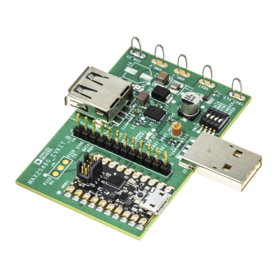
MAX25460 Evaluation Kit Board
Ordering Information
|
Tel: 781.329.4700
|
MAX25460 Evaluation Kit
appears at end of data sheet.
© 2023 Analog Devices, Inc. All rights reserved.
319-100999; Rev 0; 5/23
Advertisement
Table of Contents

Related Manuals for Analog Devices MAX25460


Summary of Contents for Analog Devices MAX25460
- Page 1 319-100999; Rev 0; 5/23 © 2023 Analog Devices, Inc. All rights reserved. Trademarks and registered trademarks are the property of their respective owners. One Analog Way, Wilmington, MA 01887 U.S.A. Tel: 781.329.4700 © 2023 Analog Devices, Inc. All rights reserved.
-
Page 2: Quick Start
7) Turn on the VBAT power supply output. The following procedure demonstrates the MAX25460’s 8) Start the MAX25460 GUI. Look at the message high-speed data switches and voltage adjustment capa- bar on the left of the GUI to verify that the EV kit is bility. - Page 3 MAX25460 Evaluation Kit Evaluates: MAX25460 Figure 2. MAX25460 GUI Startup Figure 3. USB Flash Drive Recognized Analog Devices │ 3 www.analog.com...
- Page 4 MAX25460 Evaluation Kit Evaluates: MAX25460 USB BC1.2 CDP Charging Cable Compensation 12) In the GUI, set Cable Comp Gain to 108mΩ and set 17) Connect the 2m USB-A extension cable to the EV kit Charge Detection to Auto_CDP. downstream USB connector (J3).
-
Page 5: Detailed Description
Evaluates: MAX25460 Detailed Description EV Kit Interface Header J1 includes input and output test points for con- The MAX25460 EV kit comes fully assembled, tested, trolling the IC and evaluating its functionality. Table 2 lists and installed with MAX25460ATGA/V+. The stand-alone the individual pins and their functions. -
Page 6: Basic Functionality
SYNC pin generates clock output for synchronization of other devices. If enabled, spread spectrum is also present on SYNC output to reduce EMI of the device synchronized to MAX25460. SYNC output is 180° out of phase with internal clock to further SYNC help reduce EMI. - Page 7 Evaluates: MAX25460 MAX25460 GUI A low-impedance ground connection between the input and output capacitors is required for reliable operation. The latest GUI can be downloaded from the MAX25460 Make this connection through the ground pour on the EV kit webpage: https://www.analog.com/en/design- exposed pad.
-
Page 8: Programming Procedure
3) If the firmware image from the EV kit webpage has a later date, follow the Programming Procedure to up- date the Pico Board’s firmware to the latest version. This update requires the MAX25460 EV kit, a USB Micro-B cable, and a PC with USB Write access. Programming Procedure •... - Page 9 MAX25460 Evaluation Kit Evaluates: MAX25460 MAX25460 EV Kit Bill of Materials REFERENCE DESCRIPTION PART NUMBER MANUFACTURER CERAMIC CAPACITOR (0402) 2200PF 10% 50V X7R GRM155R71H222KA01 MURATA ALUMINUM-ELECTROLYTIC CAPACITOR 22UF 20% 50V EEE-FT1H220AR PANASONIC C3, C4, C12, C16, C18, C20 CERAMIC CAPACITOR (0402) 0.1UF 10% 50V X7R...
- Page 10 MAX25460 Evaluation Kit Evaluates: MAX25460 MAX25460 EV Kit Schematic Analog Devices │ 10 www.analog.com...
- Page 11 MAX25460 Evaluation Kit Evaluates: MAX25460 MAX25460 EV Kit Layout MAX25460 EV Kit PCB Layout—Top View MAX25460 EV Kit PCB Layout—Layer 3 MAX25460 EV Kit PCB Layout—Layer 2 MAX25460 EV Kit PCB Layout—Bottom View Analog Devices │ 11 www.analog.com...
-
Page 12: Revision History
Information furnished by Analog Devices is believed to be accurate and reliable. However, no responsibility is assumed by Analog Devices for its use, nor for any infringements of patents or other rights of third parties that may result from its use.Specifications subject to change without notice. No license is granted by implication or otherwise under any patent or patent rights of Analog Devices.
Need help?
Do you have a question about the MAX25460 and is the answer not in the manual?
Questions and answers