Goodwe SDT Series User Manual
Grid-tied pv inverter
Hide thumbs
Also See for SDT Series:
- User manual (12 pages) ,
- User manual (17 pages) ,
- User manual (12 pages)
Table of Contents
Advertisement
Advertisement
Table of Contents

Related Manuals for Goodwe SDT Series


Summary of Contents for Goodwe SDT Series
- Page 1 User Manual Grid-Tied PV Inverter SDT Series (8-30 kW) G3 V1.3-2024-01-25...
- Page 2 Copyright ©GoodWe Technologies Co., Ltd., 2023. All rights reserved No part of this manual can be reproduced or transmitted to the public platform in any form or by any means without the prior written authorization of GoodWe Technologies Co., Ltd. Trademarks and other GOODWE trademarks are trademarks of GoodWe Technologies Co.,...
-
Page 3: Table Of Contents
User Manual V1.3-2024-01-25 CONTENT Content 1 About This Manual ..................1 1.1 Applicable Model ......................1 1.2 Target Audience ......................1 1.3 Symbol Definition .......................2 2 Safety Precaution ..................3 2.1 General Safety ......................3 2.2 DC Side .........................3 2.3 AC Side .........................4 2.4 Inverter Installation ....................4 2.5 Personnel Requirements ...................4 3 Product Introduction ..................5 3.1 Application Scenarios ....................5... - Page 4 User Manual V1.3-2024-01-25 CONTENT 6.5.1 RS485 Communication Networking ................... 33 6.5.2 Power Limit Networking ...................... 34 6.5.3 24H Load Monitoring ......................41 6.5.4 Connecting the Communication Cable ................42 7 Equipment Commissioning ..............47 7.1 Check Items before Power On ................47 7.2 Power On ........................
-
Page 5: About This Manual
All the installers and users have to be familiar with the product features, functions, and safety precautions. This manual is subject to update without notice. For more product details and latest documents, visit https://en.goodwe.com/. 1.1 Applicable Model... -
Page 6: Symbol Definition
01 About This Manual User Manual V1.3-2024-01-25 1.3 Symbol Definition Different levels of warning messages in this manual are defined as follows: DANGER Indicates a high-level hazard that, if not avoided, will result in death or serious injury. WARNING Indicates a medium-level hazard that, if not avoided, could result in death or serious injury. CAUTION Indicates a low-level hazard that, if not avoided, could result in minor or moderate injury. -
Page 7: Safety Precaution
For more warranty details, visit: • https://en.goodwe.com/warranty.asp. 2.2 DC Side DANGER Connect the DC cables using the delivered DC connectors and terminals. -
Page 8: Ac Side
User Manual V1.3-2024-01-25 02 Safety Precaution 2.3 AC Side WARNING • The voltage and frequency at the connecting point should meet the on-grid requirements. • Additional protective devices like circuit breakers or fuses are recommended on the AC side. The specification of the protective device should be at least 1.25 times the rated AC output rated current. -
Page 9: Product Introduction
3 Product Introduction 3.1 Application Scenarios The SDT Series inverter is a three-phase PV string grid-tied inverter. The inverter converts the DC power generated by the PV module into AC power and feeds it into the utility grid. The intended use of the inverter is as follows:... -
Page 10: Circuit Diagram
03 Product Introduction User Manual V1.3-2024-01-25 3.2 Circuit Diagram GW8000-SDT-30, GW10K-SDT-30, GW10K-SDT-EU30, GW12K-SDT-30 and GW15K-SDT-30: DC Switch Filter DC/AC Inverter Filter Filter Circuit Filter Output Disconnecting Relay AC SPD DC SPD GW12KLV-SDT-C30, GW17K-SDT-30, GW20K-SDT-30, GW23K-SDT-C30, GW25K-SDT-C30 and GW27K-SDT-C30: DC Switch Filter DC/AC Inverter... -
Page 11: Supported Grid Types
User Manual V1.3-2024-01-25 03 Product Introduction 3.3 Supported Grid Types TN-S TN-C TN-C-S Inverter Inverter Inverter Inverter Inverter 3.4 Functionalities AFCI (Optional) AFCI functionality is to detect the DC electric arc fault. If there is any, the inverter is able to enable self-protection automatically. - Page 12 03 Product Introduction User Manual V1.3-2024-01-25 RSD (Optional) Optionally, inverters with RSD function equips with a built-in signal transmitter to communicate with module-level smart controller installed on the external of the PV strings. In case of an emergency, by turning off the AC circuit breaker at the output side of the inverter, the transmitter inside of the inverter will be cut off, consequently to interrupt the current output of the PV strings.
-
Page 13: Inverter Operation Mode
User Manual V1.3-2024-01-25 03 Product Introduction 24h Load Monitoring (Optional) The smart meter measures the data of the grid side and transmits it to the inverter. The inverter transmits the grid side date and the power generation date to the monitoring platform via a communication module, and then monitoring platform calculates the load power consumption and the 24H load monitoring is realized. -
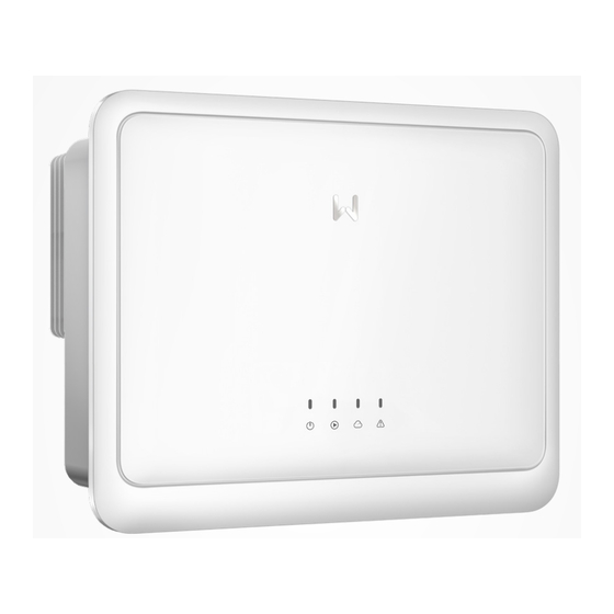
Page 14: Appearance
03 Product Introduction User Manual V1.3-2024-01-25 3.6 Appearance 3.6.1 Parts China Version (8-15kW) Parts Description DC Switch To start or stop DC input. PV Input Terminal To connect the PV module DC input cables. To connect the communication cable such as RS485, smart meter, Emergency Power Off, Remote Communication Terminal Shutdown, Dry Contact, DRED(for Australia only) or... - Page 15 User Manual V1.3-2024-01-25 03 Product Introduction China Version (17-30kW) Parts Description DC Switch To start or stop DC input. Ventilation Valve • To connect the PV module DC input cables. PV Input Terminal • GW25K-SDT-P30, GW27K-SDT-P30, GW30K- SDT-C30: 4 x PV+/PV-, other models: 3 x PV+/PV- To connect the communication cable such as RS485, smart meter, Emergency Power Off, Remote Communication Terminal...
- Page 16 03 Product Introduction User Manual V1.3-2024-01-25 Non-China (GW8000-SDT-30, GW10K-SDT-30, GW10K-SDT-EU30, GW12K-SDT-30, GW15K-SDT-30) Parts Description DC Switch To start or stop DC input. PV Input Terminal To connect the PV module DC input cables. To connect the communication cable such as RS485, smart meter, Emergency Power Off, Remote Communication Terminal Shutdown, Dry Contact, DRED(for Australia only) or...
- Page 17 User Manual V1.3-2024-01-25 03 Product Introduction Non-China (GW12KLV-SDT-C30, GW17K-SDT-30, GW17KLV-SDT-C30, GW20K-SDT-30, GW25K-SDT-C30, GW30K-SDT-C30) Parts/Printed Word Description DC Switch To start or stop DC input. Ventilation Valve • To connect the PV module DC input cables. PV Input Terminal • GW25K-SDT-P30, GW27K-SDT-P30, GW30K-SDT-C30: 4 x PV+/PV-, other models: 3 x PV+/PV- The maximum current that ports of each inverter MPPT Value of Max.
-
Page 18: Dimensions
03 Product Introduction User Manual V1.3-2024-01-25 3.6.2 Dimensions China Version (8-15kW) China Version (17-30kW) - Page 19 User Manual V1.3-2024-01-25 03 Product Introduction Non-China Version(GW8000-SDT-30, GW10K-SDT-30, GW10K-SDT-EU30, GW12K- SDT-30, GW15K-SDT-30) Non-China Version(GW12KLV-SDT-C30, GW17K-SDT-30, GW17KLV-SDT-C30, GW20K-SDT-30, GW25K-SDT-C30, GW30K-SDT-C30)
-
Page 20: Indicators
03 Product Introduction User Manual V1.3-2024-01-25 3.6.3 Indicators Inverters Designed with LCD Indicator Status Description ON = WIRELESS IS CONNECTED/ACTIVE BLINK 1 = WIRELESS SYSTEM IS RESETTING BLINK 2 = NOT CONNECTED TO THE ROUTER OR BASE STATION BLINK 4 = NOT CONNECTED TO MONITORING SERVER BLINK = RS485 IS CONNECTED OFF = WIRELESS IS RESTORING FACTORY DEFAULT SETTING ON = THE INVERTER IS FEEDING POWER... -
Page 21: Nameplate
User Manual V1.3-2024-01-25 03 Product Introduction 3.6.4 Nameplate The nameplate is for reference only. Goodwe trademark, product type, and product model Technical parameters Safety symbols and certification marks Contact information and serial number... -
Page 22: Check And Storage
04 Check and Storage User Manual V1.3-2024-01-25 4 Check and Storage 4.1 Check Before Receiving Check the following items before receiving the product. 1. Check the outer packing box for damage, such as holes, cracks, deformation, and others signs of equipment damage. Do not unpack the package and contact the supplier as soon as possible if any damage is found. -
Page 23: Storage
04 Check and Storage User Manual V1.3-2024-01-25 NOTICE [1] The type of the mounting plate epends on the model of the inverter. [2] The number of PV connectors equals with the number of the inverter's DC input terminals. [3] The number of expansion bolts depends on the inverter model. [4] Communication module types are available: WiFi/4G/Bluetooth/LAN. -
Page 24: Installation
User Manual V1.3-2024-01-25 05 Installation 5 Installation 5.1 Installation Requirements Installation Environment Requirements 1. Do not install the equipment in a place near flammable, explosive, or corrosive materials. 2. Install the equipment on a surface that is solid enough to bear the inverter weight. 3. - Page 25 User Manual V1.3-2024-01-25 05 Installation ≥300mm ≥200mm ≥200mm ≥300mm ≥500mm ALT: 4000m IP66 0%~100%RH Mounting Support Requirements • The mounting support shall be nonflammable and fireproof. • Make sure that the support surface is solid enough to bear the product weight load. •...
-
Page 26: Inverter Installation
User Manual V1.3-2024-01-25 05 Installation Installation Tool Requirements The following tools are recommended when installing the equipment. Use other auxiliary tools on site if necessary. M4/M5 Goggles Safety shoes Safety gloves Dust mask Torque wrench Terminal Diagonal pliers Wire stripper Hammer drill Heat gun crimping tool... -
Page 27: Installing The Inverter
User Manual V1.3-2024-01-25 05 Installation 5.2.2 Installing the Inverter NOTICE • Avoid the water pipes and cables buried in the wall when drilling holes. • Wear goggles and a dust mask to prevent the dust from being inhaled or contacting eyes when drilling holes. - Page 28 User Manual V1.3-2024-01-25 05 Installation GW12KLV-SDT-C30, GW17K-SDT-30, GW17KLV-SDT-C30, GW20K-SDT-30, GW23K- SDT-C30, GW25K-SDT-C30, GW25K-SDT-P30, GW27K-SDT-C30, GW27K-SDT-P30, GW30K- SDT-C30 Step 1 (Optional, For Brazil Only) For 127V/220V grid, replace the nameplate on the inverterwith the nameplate delivered. Step 2 Put the mounting plate on the wall horizontally and mark positions for drilling holes. Step 3 Drill holes to a depth of 60 mm using the hammer drill.
-
Page 29: Electrical Connection
User Manual V1.3-2024-01-25 06 Electrical Connection 6 Electrical Connection 6.1 Safety Precautions DANGER • Disconnect the DC switch and the AC output switch of the inverter to power off the equipment before any electrical connections. Do not work with power on. Otherwise, an electric shock may occur. - Page 30 06 Electrical Connection User Manual V1.3-2024-01-25 Cable Requirements Cable Specification Cable Type Outer Diameter Cross-sectional Area (mm (mm) DC input cable 6.1 - 8 Recommended: 4 - 6 PV cable that (MC4) meets 1100V DC input cable standard. 5.5 - 8 Recommended: 4 - 6 (Jinko) For Brazil LV inverters,...
-
Page 31: Connecting The Pe Cable
User Manual V1.3-2024-01-25 06 Electrical Connection 6.2 Connecting the PE Cable WARNING • The PE cable connected to the enclosure of the inverter cannot replace the PE cable connected to the AC output port. Both of the two PE cables must be securely connected. •... - Page 32 06 Electrical Connection User Manual V1.3-2024-01-25 NOTICE Install one AC circuit breaker for each inverter. Multiple inverters cannot share one AC circuit breaker. An AC circuit breaker should be installed on the AC side to make sure that the inverter can safely disconnect the grid when an exception happens.
- Page 33 User Manual V1.3-2024-01-25 06 Electrical Connection Step 1 Prepare the AC cable. Step 2 Disassemble the AC terminal cover. Step 3 Crimp the AC cable into the OT terminals, and lead the crimped cable into the AC cable. Step 4 Remove the wiring baffle on the AC terminal block and the cable fixing screws. Step 5 Tighten AC cable into the AC terminal block.
-
Page 34: Connecting The Pv Input Cable
06 Electrical Connection User Manual V1.3-2024-01-25 6.4 Connecting the PV Input Cable DANGER Confirm the following information before connecting the PV string to the inverter. Otherwise, the inverter may be damaged permanently or even cause fire and cause personal and property losses. - Page 35 User Manual V1.3-2024-01-25 06 Electrical Connection Connecting the DC Input Cable Step 1 Prepare DC cables. Step 2 Disassemble the PV connectors. Step 3 Crimp the DC cable, and assemble the PV connectors. Step 4 Fasten the PV connector. Step 5 Measure the DC input voltage. Step 6 Plug the PV connectors into the DC input terminals.
- Page 36 06 Electrical Connection User Manual V1.3-2024-01-25 Jinko DC Connector 7~8mm 7~8mm Click YQK-70 GW12KLV-SDT-C30 :≤850V GW17KLV-SDT-C30 :≤850V Others: ≤1100V Click...
-
Page 37: Communication
User Manual V1.3-2024-01-25 06 Electrical Connection Conect Y-Branch PV Connectors(Optional) NOTICE If it is needed, please use the Y-branch PV connector that is with the same model or specification of the inverter PV connector. The manufacturer shall not be liable for inverter damage caused by using incompatible Y-branch PV connector. -
Page 38: Power Limit Networking
06 Electrical Connection User Manual V1.3-2024-01-25 6.5.2 Power Limit Networking When all loads in the PV system cannot consume the generated electricity, the surplus power will be fed into the grid. In this case, it is possible to monitor the power generation with an Smart Meter, Smart DataLogger, or SEC1000 (smart energy controller) to control the amount of power fed into the grid. - Page 39 User Manual V1.3-2024-01-25 06 Electrical Connection WARNING 1. The place to snap fit the CT shall be near the grid connection point and the installation direction must be right. “-->” of CT refers that the inverter current flows to the Grid. If CT is installed reversely, the inverter will be triggered with an alarm and unable to realize the power limit function.
- Page 40 06 Electrical Connection User Manual V1.3-2024-01-25 Power limit networking with single inveter (GM3000C) WARNING 1. The place to snap fit the CT shall be near the grid connection point and the installation direction must be right. “-->” of CT refers that the inverter current flows to the Grid. If CT is installed reversely, the inverter will be triggered with an alarm and unable to realize the power limit function.
- Page 41 3. Select whether to use GM3000 smart meter according to the maximum over current, the cables or the copper busbar in the system. For details, please consult GoodWe Solar Academy for help. CT is delivered with the smart meter. 4. The load current of each phase shall be less than 120A.
- Page 42 06 Electrical Connection User Manual V1.3-2024-01-25 Power limit networking with multi inveter (EzLogger Pro+GMK330) Inverter 1 ..Inverter N Meter Grid N L1 L2 L3 Server GMK330 Load PV String PV String Circuit RESET RESET Breaker Router L1 L2 L3 EzLogger Power limit networking with multi inveter (EzLogger Pro+GM330) Meter...
- Page 43 User Manual V1.3-2024-01-25 06 Electrical Connection Power limit networking with multi inveter (SEC1000) WARNING 1. Connect SEC1000 AC cable to a 3L/N/PE Grid. The voltage of the Grid shall be within allowable voltage sampling scope of SEC1000. 2. The place to snap fit the CT shall be near the Grid-Tied entry point. Make sure the connecting direction is right.
- Page 44 06 Electrical Connection User Manual V1.3-2024-01-25 Based on the external CT test current, the recommended CT specification are: Current Scope Description Note < 250A CT 200A Acrel/AKH-0.66 CT for power limit, closed type (born (200A/5A) dimension 31mm*11mm, Φ22mm) CT 250A/5A Acrel/AKH- CT for power limit, open type (opening 0.66-K-30x20-250/5 size 32mm*22mm), 0.5% in precision...
-
Page 45: Load Monitoring
User Manual V1.3-2024-01-25 06 Electrical Connection 6.5.3 24H Load Monitoring The smart meter such as GMK330, GM330 GM3000 and GM3000C measures the data of the grid side and transmits it to the inverter. The inverter transmits the grid side date and the power generation date to the monitoring platform via a communication module, and then monitoring platform calculates the load power consumption and the 24H load monitoring is realized. -
Page 46: Connecting The Communication Cable
06 Electrical Connection User Manual V1.3-2024-01-25 6.5.4 Connecting the Communication Cable NOTICE • When connecting the communication line, make sure that the wiring port definition and the equipment are fully matched, and the cable alignment path should avoid interference sources, power lines, etc., so as not to affect signal reception. •... - Page 47 User Manual V1.3-2024-01-25 06 Electrical Connection Function Terminal Definition Description 7: Remote Shutdown/ For remote shutdown(Only for Remote EPO/ EPO - Europe), Remote Shutdown/ For Emergency Power Off (Only 8: Remote Shutdown/ Shutdown for India). EPO + 9: I/O1+ To receive the Dry Contact signal Dry Contact 10: Reserved (220V)
- Page 48 06 Electrical Connection User Manual V1.3-2024-01-25 Step 1 Prepare the communication cable. Step 2 Disassemble the integrated communication connector of the user end in order. Step 3 Connect the communication cable to the communication terminal and fasten it. Step 4 Connect the communication terminal to the inverter.
- Page 49 User Manual V1.3-2024-01-25 06 Electrical Connection RS485 1: RS485- 9: I/O1+ 2: RS485+ 10:Reserved 3: RS485- 11:I/O1- 4: RS485+ 12:I/O2+ 13:I/O2- Smart Meter 14:I/O3+ 5: MeterB/Meter- 15:I/O3- DRED/RCR 6: MeterA/Meter+ 16:COM/DRM0 or REF_1 17:REFGEN or REF_2 Remote shutdown/ 18:DRM4/8 or DI 4 Emergency Power Off 19:DRM3/7 or DI 3 0.6N·m...
- Page 50 06 Electrical Connection User Manual V1.3-2024-01-25 NOTICE Refer to the delivered communication module user manual to get more introduction to the module. For more detailed information, visit https://en.goodwe.com/. Connecting USB-RS485 Adapter Cable Only for Brazil Models.
-
Page 51: Equipment Commissioning
07 Equipment Commissioning User Manual V1.3-2024-01-25 7 Equipment Commissioning 7.1 Check Items before Power On Check Item The inverter is firmly installed in a clean place where is well-ventilated and easy to operate. The PE cable, DC input cable, AC output cable, and communication cable are connected correctly and securely. -
Page 52: System Commissioning
08 System Commissioning User Manual V1.3-2024-01-25 8 System Commissioning 8.1 Setting Inverter Parameters via LCD NOTICE • Inverter software version shown in this document is V1.00.00. The screen shots are for reference only. The actual display may differ. • The name, range, and default value of the parameters is subject to change or adjust. The actual display prevails. - Page 53 08 System Commissioning User Manual V1.3-2024-01-25 First level menu Second level menu Normal Set language Set Safety Pac=xxx W Short press Short press Date Set Date Set Time Time Short press Short press Vpv1 = xxx V W/L Reset Ipv1 = xxx A W/L Reload Short press Short press...
-
Page 54: Inverter Parameter Introduction
08 System Commissioning User Manual V1.3-2024-01-25 8.1.2 Inverter Parameter Introduction Parameters Description Normal Home page. Indicates the real-time power of the inverter. Date Time Check the time of the country/region. Check the DC input voltage of the inverter. Check the DC input current of the inverter. Check the voltage of the utility grid. - Page 55 08 System Commissioning User Manual V1.3-2024-01-25 Parameters Description Indicates the PV-PE insulation resistance threshold value. When the Set ISO detected value is under the set value, the IOS fault occurs. With LVRT on, the inverter will stay connected with the utility grid LVRT after a short-term utility grid low voltage exception occurs.
-
Page 56: Setting Inverter Parameters Via App
2. Set grid parameters and communication parameters of the inverter. 3. Maintain the equipment. For more details, refer to the SolarGo APP User Manual. Scan the QR code or visit https:// en.goodwe.com/Ftp/EN/Downloads/User%20Manual/GW_SolarGo_User%20Manual-EN.pdf get the user manual. SolarGo App SolarGo App User Manual 8.3 Monitoring via SEMS Portal... -
Page 57: Maintenance
User Manual V1.3-2024-01-25 09 Maintenance 9 Maintenance 9.1 Power Off the Inverter DANGER • Power off the inverter before operations and maintenance. Otherwise, the inverter may be damaged or electric shocks may occur. • Delayed discharge. Wait until the components are discharged after power off. Step 1 (Optional) Issue a command to the inverter for halting the grid connection. - Page 58 User Manual V1.3-2024-01-25 09 Maintenance No. Fault Cause Solutions 1. Utility grid power The alarm will be automatically failure. cleared after the grid power supply Utility Loss 2. The AC circuit or restores. the AC breaker is Check whether the AC cable is disconnected.
- Page 59 User Manual V1.3-2024-01-25 09 Maintenance No. Fault Cause Solutions If occurs occasionaly, it may be caused a short term grid abnormity. The inverter will recover automatically after the grid is normal. If it occurs frequently, please check whether the grid voltage is within the allowed range.
- Page 60 User Manual V1.3-2024-01-25 09 Maintenance No. Fault Cause Solutions If occurs occasionaly, it may be caused a short term grid abnormity. The inverter will recover automatically after the grid is normal. If it occurs frequently, please check whether the grid voltage is within The average value of the allowed range.
- Page 61 User Manual V1.3-2024-01-25 09 Maintenance No. Fault Cause Solutions If occurs occasionaly, it may be caused a short term grid abnormity. The inverter will recover automatically after the grid is normal. If it occurs frequently, please check whether the grid voltage is within The frequency of the grid the allowed range.
- Page 62 User Manual V1.3-2024-01-25 09 Maintenance No. Fault Cause Solutions Abnormal grid, and If occurs occasionaly, it may the abnormal duratin be caused a short term grid LVRT exceeds the specified abnormity. The inverter will recover Undervoltage value of local high automatically after the grid is voltage safety regulation.
- Page 63 User Manual V1.3-2024-01-25 09 Maintenance No. Fault Cause Solutions 1. The PE cable is not 1. Please confirm if the PE cable of the connected. inverter is not connected properly. 2. When ground the PV 2. Under the scenerio of PV string Abnormal Ground.
- Page 64 User Manual V1.3-2024-01-25 09 Maintenance No. Fault Cause Solutions AC HCT Check Abnormal sampling of abnormal AC HCT GFCI HCT Check Abnormal sampling of abnormal GFCI HCT 1. The relay is abnormal or short-circuited. 2. The control circuit is abnormal. Relay Check 3.
- Page 65 User Manual V1.3-2024-01-25 09 Maintenance No. Fault Cause Solutions The reference circuit is 1.5V Ref abnormal abnormal. The reference circuit is 0.3V Ref abnormal abnormal. BUS Overvoltage P-BUS Overvoltage N-BUS 1. The PV voltage is too Overvoltage high. 2. The sampling of the Overvoltage(Slave Disconnect the AC output switch and inverter BUS voltage is...
- Page 66 User Manual V1.3-2024-01-25 09 Maintenance No. Fault Cause Solutions 1. If the problem occurs occasionally, the PV voltage Low reason might be abnormal sun light. The inverter will recover automatically without Sun light is weak or manual intervention. changing abnormally. BUS voltage Low 2.
-
Page 67: Routine Maintenance
User Manual V1.3-2024-01-25 09 Maintenance 9.5 Routine Maintenance DANGER Power off the inverter before operations and maintenance. Otherwise, the inverter may be damaged or electric shocks may occur. Maintaining Item Maintaining Method Maintaining Period Check the heat sink, air intake, and air System Clean Once 6-12 months outlet for foreign matter or dust. -
Page 68: Technical Parameters
User Manual V1.3-2024-01-25 10 Technical Parameters 10 Technical Parameters Technical Data GW8000- GW10K- GW10K- GW12K- SDT-30 SDT-30 SDT-EU30 SDT-30 Input Max.Input Power (W) 12000 15000 15000 18000 Max.Input Voltage(V) 1100 1100 1100 1100 MPPT Operating Voltage Range 140~1000 140~1000 140~1000 140~1000 MPPT Voltage Range at Nominal 250~850... - Page 69 10 Technical Parameters User Manual V1.3-2024-01-25 Max. Output Fault Current (Peak 42 (at 6.5μs) 67 (at 6.5μs) and Duration) (A) Inrush Current (Peak and 23.7 (at 50μs) Duration) (A) Nominal Output Current (A) 11.6 14.5 14.5 17.4 Power Factor ~1 (Adjustable from 0.8 leading to 0.8 lagging) Max.
- Page 70 User Manual V1.3-2024-01-25 10 Technical Parameters Derating Temperature (℃) Storage Temperature (℃) -30~+70 Relative Humidity 0~100% Max. Operating Altitude (m) 4000 Cooling Method Natural Convection User Interface LED, LCD (Optional), WLAN+APP Communication RS485, WiFi, LAN or 4G or Bluetooth(Optional) Weight (Kg) 14.7 16.2 Dimension (W×H×Dmm)
- Page 71 10 Technical Parameters User Manual V1.3-2024-01-25 Technical Data GW15K- GW17K- GW20K- GW12KLV-SDT-C30 SDT-30 SDT-30 SDT-30 Input Max.Input Power (W) 22500 25500 30000 18000 Max.Input Voltage(V) 1100 MPPT Operating Voltage Range 140~1000 140~700 MPPT Voltage Range at Nominal 480~850 520~850 520~850 260~600 Power (V) Start-up Voltage (V)
- Page 72 User Manual V1.3-2024-01-25 10 Technical Parameters Max. Output Fault Current (Peak 67 (at 6.5μs) 73 (at 6.5μs) and Duration) (A) Inrush Current (Peak and 23.7 (at 30.2 (at 50μs) Duration) (A) 50μs) Nominal Output Current (A) 21.8 24.7 29.0 29.0 Power Factor ~1 (Adjustable from 0.8 leading to 0.8 lagging) Max.
- Page 73 10 Technical Parameters User Manual V1.3-2024-01-25 Derating Temperature (℃) Storage Temperature (℃) -30~+70 Relative Humidity 0~100% Max. Operating Altitude (m) 4000 Natural Cooling Method Smart Fan Cooling Convection User Interface LED, LCD (Optional), WLAN+APP Communication RS485, WiFi, LAN or 4G or Bluetooth(Optional) Weight (Kg) 16.2 17.1...
- Page 74 User Manual V1.3-2024-01-25 10 Technical Parameters Technical Data GW17KLV-SDT-C30 GW25K-SDT-C30 GW30K-SDT-C30 Input Max.Input Power (W) 25500 37500 45000 Max.Input Voltage(V) 1100 1100 MPPT Operating Voltage 140~700 140~1000 140~1000 Range (V) MPPT Voltage Range at 260~500 550~850 550~850 Nominal Power (V) Start-up Voltage (V) Nominal Input Voltage (V) Max.
- Page 75 10 Technical Parameters User Manual V1.3-2024-01-25 Max. Output Fault Current (Peak 115 (at 6.5μs) 95 (at 6.5μs) 115 (at 6.5μs) and Duration) (A) Inrush Current (Peak and 29.4 (at 50μs) Duration) (A) Nominal Output Current (A) 43.5 36.3 43.5 Power Factor ~1 (Adjustable from 0.8 leading to 0.8 lagging) Max.
- Page 76 User Manual V1.3-2024-01-25 10 Technical Parameters Derating Temperature (℃) Storage Temperature (℃) -30~+70 Relative Humidity 0~100% Max. Operating Altitude (m) 4000 Cooling Method Smart Fan Cooling User Interface LED, LCD (Optional), WLAN+APP Communication RS485, WiFi, LAN or 4G or Bluetooth(Optional) Weight (Kg) 20.5 19.7...
- Page 77 GoodWe Website GoodWe Technologies Co., Ltd. No. 90 Zijin Rd., New District, Suzhou, 215011, China www.goodwe.com service@goodwe.com Local Contacts...
Need help?
Do you have a question about the SDT Series and is the answer not in the manual?
Questions and answers