Goodwe SDT G2 Series User Manual
Grid-tied pv inverter
Hide thumbs
Also See for SDT G2 Series:
- Quick installation manual (106 pages) ,
- User manual (77 pages) ,
- User manual (75 pages)
Table of Contents
Advertisement
Advertisement
Table of Contents

Related Manuals for Goodwe SDT G2 Series


Summary of Contents for Goodwe SDT G2 Series
- Page 1 User Manual Grid-Tied PV Inverter SDT G2 Series V1.0-2022-03-15...
- Page 2 Copyright ©GoodWe Technologies Co., Ltd., 2022. All rights reserved No part of this manual can be reproduced or transmitted to the public platform in any form or by any means without the prior written authorization of GoodWe Technologies Co., Ltd. Trademarks and other GOODWE trademarks are trademarks of GoodWe Technologies Co., Ltd.
-
Page 3: Table Of Contents
Content User Manual V1.0-2022-03-15 CONTENTS 1 About This Manual ............1 1.1 Applicable Model ..................1 1.2 Target Audience ..................1 1.3 Symbol Definition ..................2 1.4 Updates ...................... 2 2 Safety Precaution ............3 2.1 General Safety ................... 3 2.2 DC Side ....................... 3 2.3 AC Side ....................... - Page 4 User Manual V1.0-2022-03-15 Content 6 Electrical Connection ............ 21 6.1 Safety Precautions ................. 21 6.2 Connecting the PE Cable ................ 21 6.3 Connecting the PV Input Cable .............. 22 6.4 Connecting the AC Output Cable ............28 6.5 Communication ..................32 6.5.1 Connecting the Communication Cable (optional) .........32 6.5.2 Installing the Communication Module (optional) ..........36 7 Equipment Commissioning ...........
-
Page 5: About This Manual
All the installers and users have to be familiar with the product features, functions, and safety precautions. This manual is subject to update without notice. For more product details and latest documents, visit https://en.goodwe.com/. 1.1 Applicable Model... -
Page 6: Symbol Definition
01 About This Manual User Manual V1.0-2022-03-15 1.3 Symbol Definition Different levels of warning messages in this manual are defined as follows: DANGER Indicates a high-level hazard that, if not avoided, will result in death or serious injury. WARNING Indicates a medium-level hazard that, if not avoided, could result in death or serious injury. CAUTION Indicates a low-level hazard that, if not avoided, could result in minor or moderate injury. -
Page 7: Safety Precaution
Strictly follow the installation, operation, and configuration instructions in this manual. The manufacturer shall not be liable for equipment damage or personal injury if you do not follow the instructions. For more warranty details, visit https://en.goodwe.com/warranty. 2.2 DC Side DANGER Connect the DC cables using the delivered DC connectors and terminals. -
Page 8: Ac Side
02 Safety Precaution User Manual V1.0-2022-03-15 2.3 AC Side WARNING • The voltage and frequency at the connecting point should meet the on-grid requirements. • An additional protective device like the circuit breaker or fuse is recommended on the AC side. -
Page 9: Product Introduction
3 Product Introduction 3.1 Application Scenarios The SDT G2 Series inverter is a three-phase PV string grid-tied inverter. The inverter converts the DC power generated by the PV module into AC power and feeds it into the utility grid. The... -
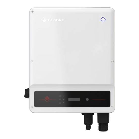
Page 10: Appearance
03 Product Introduction User Manual V1.0-2022-03-15 3.4 Appearance 3.4.1 Parts GW4K-DT, GW4000-SDT-20, GW5K-DT, GW8K-DT, GW10KT-DT GW5000-SDT-20, GW6K-DT, GW6000- SDT-20 GW12KT-DT, GW15KT-DT Indicator LCD (optional) Button (optional) PE Terminal Mounting Plate 6. PV Input Terminal Bluetooth or Wi-Fi/LAN Kit or DC Switch Ventilation valve WiFi or 4G or GPRS Port Smart Meter or RS485... - Page 11 User Manual V1.0-2022-03-15 03 Product Introduction GW8KAU-DT, GW10KAU-DT, GW15KAU-DT, GW20KAU-DT, GW17KT-DT, GW20KT-DT, GW25KT-DT GW8000-SDT-20, GW10K-SDT-20 GW12K-SDT-20, GW12KLV-SDT-20, GW15K-SDT-20, GW17K-SDT-20, GW20K-SDT-20 LED Indicator LCD (optional) Button (optional) PE Terminal Mounting Plate DC Switch USB Port (For Brazil PV Input Terminal (PV1) PV Input Terminal (PV2) only) Bluetooth or Wi-Fi/...
- Page 12 03 Product Introduction User Manual V1.0-2022-03-15 Name Description PV Input Terminal Used to connect the PV module DC input cables. DC Switch Start or stop DC input. USB Port Reserved. USB Port is used for system upgrade and configuration. Ventilation valve Communication Used to connect communication modules like Bluetooth, WiFi, LAN, 4G, Port...
-
Page 13: Dimension
User Manual V1.0-2022-03-15 03 Product Introduction 3.4.2 Dimension Dimensions of GW4K-DT, GW4000-SDT-20, GW5K-DT, GW5000-SDT-20, GW6K-DT, GW6000-SDT-20, GW10KT-DT: 354mm 147mm 200mm Dimensions of GW8K-DT, GW10KT-DT, GW12KT-DT, GW15KT-DT: 354mm 155mm 200mm Dimensions of GW8KAU-DT, GW10KAU-DT, GW15KAU-DT, GW20KAU-DT, GW17KT-DT, GW20KT-DT, GW25KT-DT, GW25KT-DT, GW8000-SDT-20, GW10K-SDT-20: 175mm 415mm 110mm 120mm... - Page 14 03 Product Introduction User Manual V1.0-2022-03-15 Dimensions of GW12K-SDT-20, GW12KLV-SDT-20, GW15K-SDT-20, GW17K-SDT-20, GW20K-SDT-20: 198mm 415mm 110mm 120mm...
-
Page 15: Indicators
User Manual V1.0-2022-03-15 03 Product Introduction 3.4.3 Indicators As a human-computer interaction interface, LCD display panel comprises of LED indicators, buttons and LCD display on the front panel of the inverter. LED indicates the working status of the inverter. Buttons and LCD are used for configuration and viewing parameters. Inverters Designed with LCD Indicator Status... - Page 16 03 Product Introduction User Manual V1.0-2022-03-15 Inverters Designed without LCD Indicator Status Description ON = EQUIPMENT POWER ON OFF = EQUIPMENT POWER OFF ON = THE INVERTER IS FEEDING POWER OFF = THE INVERTER IS NOT FEEDING POWER SINGLE SLOW FLASH = SELF CHECK BEFORE CONNECTING TO THE GRID SINGLE FLASH = CONNECTING TO THE GRID ON = WIRELESS IS CONNECTED/ACTIVE...
-
Page 17: Nameplate
User Manual V1.0-2022-03-15 03 Product Introduction 3.4.4 Nameplate The nameplate is for reference only. Goodwe trademark, product type, and product model Product: Grid-Tied PV Inverter Model : *****-*** ****V Vmax PV: d.c. ***...***V MPPT voltage range: d.c. Max. PV current: **/**A d.c. -
Page 18: Check And Storage
04 Check and Storage User Manual V1.0-2022-03-15 4 Check and Storage 4.1 Check Before Receiving Check the following items before receiving the product. 1. Check the outer packing box for damage, such as holes, cracks, deformation, and others signs of equipment damage. Do not unpack the package and contact the supplier as soon as possible if any damage is found. -
Page 19: Storage
04 Check and Storage User Manual V1.0-2022-03-15 NOTICE • The number of expansion bolts, screws, PV connectors, AC cable OT Terminal, and PIN terminals are various depending on the different inverters. The actual accessories may differ. • Communication module types including WiFi, 4G, LAN, GPRS, Bluetooth, etc. The actual module delivered depends on the communication method of the selected inverter. -
Page 20: Installation
05 Installation User Manual V1.0-2022-03-15 5 Installation 5.1 Installation Requirements Installation Environment Requirements 1. Do not install the equipment in a place near flammable, explosive, or corrosive materials. 2. Install the equipment on a surface that is solid enough to bear the inverter weight. 3. - Page 21 User Manual V1.0-2022-03-15 05 Installation Installation Angle Requirements • Install the inverter vertically or at a maximum back tilt of 15 degrees. • Do not install the inverter upside down, forward tilt, back forward tilt, or horizontally. Installation Tool Requirements The following tools are recommended when installing the equipment.
-
Page 22: Inverter Installation
05 Installation User Manual V1.0-2022-03-15 5.2 Inverter Installation 5.2.1 Moving the Inverter CAUTION Move the inverter to the site before installation. Follow the instructions below to avoid personal injury or equipment damage. 1. Consider the weight of the equipment before moving it. Assign enough personnel to move the equipment to avoid personal injury. - Page 23 05 Installation User Manual V1.0-2022-03-15 NOTICE Installation method of GW4K-DT, GW4000-SDT-20, GW5K-DT, GW5000-SDT-20, GW6K-DT, GW6000-SDT-20, GW10KT-DT, GW12KT-DT, GW15KT-DT inverter: 1.2~2N·m NOTICE Installation method of GW8KAU-DT, GW10KAU-DT, GW15KAU-DT, GW20KAU-DT, GW17KT-DT, GW20KT-DT, GW25KT-DT, GW8000-SDT-20, GW10K-SDT-20, GW12K-SDT-20, GW12KLV-SDT-20, GW15K-SDT-20, GW17K-SDT-20, GW20K-SDT-20 inverter:...
- Page 24 05 Installation User Manual V1.0-2022-03-15 1.2~2N·m NOTICE For Australia and New Zealand: GW15KAU-DT, GW20KAU-DT. 1.2~2N·m...
-
Page 25: Electrical Connection
06 Electrical Connection User Manual V1.0-2022-03-15 6 Electrical Connection 6.1 Safety Precautions DANGER • Disconnect the DC switch and the AC output switch of the inverter to power off the equipment before any electrical connections. Do not work with power on. Otherwise, an electric shock may occur. -
Page 26: Connecting The Pv Input Cable
06 Electrical Connection User Manual V1.0-2022-03-15 6.3 Connecting the PV Input Cable DANGER Confirm the following information before connecting the PV string to the inverter. Otherwise, the inverter may be damaged permanently or even cause fire and cause personal and property losses. - Page 27 06 Electrical Connection User Manual V1.0-2022-03-15 NOTICE Seal the PV input terminals using waterproof covers when they are not to be used. Otherwise, the ingress protection rating will be influenced. Connecting the DC Input Cable(with PV box) NOTICE The PV box should be installed when GW15KAU-DT or GW20KAU-DT is used in Australia and in New Zealand.
- Page 28 06 Electrical Connection User Manual V1.0-2022-03-15 Use a multimeter to measure the DC voltage and check the polarity of the connectors. Click Click Staubli MC4 DC Connector...
- Page 29 06 Electrical Connection User Manual V1.0-2022-03-15 7~8mm 7~8mm Use a multimeter to measure the DC voltage and check the polarity of the connectors. Click Click...
- Page 30 06 Electrical Connection User Manual V1.0-2022-03-15 Connecting the DC Input Cable (without PV box) Step 1 Prepare DC cables. Step 2 Crimp the crimp contacts. Step 3 Disassemble the PV connectors. Step 4 Make the DC cable and detect the DC input voltage. Step 5 Plug the PV connectors into the PV terminals.
- Page 31 06 Electrical Connection User Manual V1.0-2022-03-15 Staubli MC4 DC Connector 7~8mm 7~8mm Use a multimeter to measure the DC voltage and check the polarity of the connectors. Click Click...
-
Page 32: Connecting The Ac Output Cable
06 Electrical Connection User Manual V1.0-2022-03-15 6.4 Connecting the AC Output Cable WARNING • Do not connect loads between the inverter and the AC switch directly connected to it. • Where an external RCD (Residual Current Device) is required in addition to the built-in RCMU (Residual Current Monitoring Unit), a type A RCD must be used to avoid tripping. - Page 33 06 Electrical Connection User Manual V1.0-2022-03-15 NOTICE For models: GW4K-DT, GW4000-SDT-20, GW5K-DT, GW5000-SDT-20, GW6K-DT, GW6000-SDT-20, GW10KT-DT, GW12KT-DT, GW15KT-DT 40mm 4-10kW: 13mm≤Φ≤18mm 12-15kW: 18mm≤Φ≤25mm 4-10kW: 4mm²≤S≤10mm² 12-15kW: 6mm²≤S≤16mm² 0.6N·m...
- Page 34 06 Electrical Connection User Manual V1.0-2022-03-15 NOTICE For models: GW8000-SDT-20, GW10K-SDT-20, GW12K-SDT-20, GW12KLV-SDT-20, GW15K-SDT-20, GW17K-SDT-20, GW20K-SDT-20. NOTICE • Make sure that the cables are connected correctly and firmly after connections. Clean all the debris in the maintenance compartment. • Seal the AC output terminal to ensure the Ingress Protection Rating.
- Page 35 06 Electrical Connection User Manual V1.0-2022-03-15 NOTICE For models: GW8KAU-DT, GW10KAU-DT, GW15KAU-DT, GW20KAU-DT, GW17KT-DT, GW20KT-DT, GW25KT-DT. NOTICE • Make sure that the cables are connected correctly and firmly after connections. Clean all the debris in the maintenance compartment. • Seal the AC output terminal to ensure the Ingress Protection Rating.
-
Page 36: Communication
06 Electrical Connection User Manual V1.0-2022-03-15 6.5 Communication 6.5.1 Connecting the Communication Cable (optional) NOTICE Make sure that the communication device is connected to the right COM port. Route the communication cable far away from any interference source or power cable to prevent the signal from being influenced. - Page 37 06 Electrical Connection User Manual V1.0-2022-03-15 Power limit networking scenario (single inverter) GM3000 Inverter Grid Meter Three-phase circuit breaker Single-phase circuit breaker Load Power limit networking scenario (multi inverters) Ethernet RS485+ SEC1000 RS485- Router Cloud Inverter N Inverter 1 Three-phase Grid Meter circuit breaker...
- Page 38 06 Electrical Connection User Manual V1.0-2022-03-15 Connecting the Communication Cable(RS485, Meter, and DRED) NOTICE Connect the RS485 cable, meter cable, and DRED cable using a 6PIN communication terminal as follows. DRED RS485/ Meter 6.5mm 25mm RS485/Meter DRED 0.3~0.4N·m 1: RS485 B 1: DRM1/5 2: RS485 B 2: DRM2/6...
- Page 39 06 Electrical Connection User Manual V1.0-2022-03-15 Connecting the Communication Cable(RS485, Meter, and Remote shutdown) NOTICE Connect the remote shutdown cable using a 2PIN communication terminal as follows. RS485 6.5mm 25mm 0.6~0.8N·m RS485/Meter Remote shutdown +: METER+/RS485 A +: DRM4/8 -: METER-/RS485 B -: REFGen...
-
Page 40: Installing The Communication Module (Optional)
NOTICE • Refer to the delivered communication module user manual to get more introduction to the module. For more detailed information, visit https://en.goodwe.com/. • Remove the communication module using the unlock tool. The manufacturer shall not be liable for the port damage if the module is removed without the unlock tool. -
Page 41: Equipment Commissioning
07 Equipment Commissioning User Manual V1.0-2022-03-15 7 Equipment Commissioning 7.1 Check Items Before Switching Power ON Check Item The inverter is firmly installed in a clean place where is well-ventilated and easy to operate. The PE cable, DC input cable, AC output cable, and communication cable are connected correctly and securely. -
Page 42: System Commissioning
08 System Commissioning User Manual V1.0-2022-03-15 8 System Commissioning 8.1 Indicators and Button Inverters Designed with LCD Type Status Description Steady yellow Communication status is normal. Communication is reseting or Single yellow blinking restarting. Double yellow The inverter is not connected to the blinking router. - Page 43 08 System Commissioning User Manual V1.0-2022-03-15 Inverters Designed without LCD Type Status Description Steady Green Power on. Power off. Power The power grid is working normally. Steady Green The inverter is on grid. The inverter is off grid. Operating Single Green Slow Blinking Self-check before grid tying. Single Green Fast Blinking The inverter is to be grid-tied.
-
Page 44: Setting Inverter Parameters Via Lcd
08 System Commissioning User Manual V1.0-2022-03-15 8.2 Setting Inverter Parameters via LCD NOTICE • Inverter software version shown in this document is V1.00.00.13. The screen shots are for reference only. The actual display may differ. • The name, range, and default value of the parameters is subject to change or adjust. The actual display prevails. - Page 45 08 System Commissioning User Manual V1.0-2022-03-15 Previous page Long press Long press for 2s Long press for 2s Long press for 2s for 2s Set Time 2000-00-00 00:00 2000-00-00 00:00 2000-00-00 00:00 ······ Pac = xxx W Short press 4G and GPRS WiFi module Set OK Wait...
-
Page 46: Inverter Parameter Introduction
08 System Commissioning User Manual V1.0-2022-03-15 Previous page Short press Short press Short press Short press Long press for 2s Set ARC Self Check ARC Enable ARC Disable Fault Clear Pac = xxx W Short press Set OK Set Fail Short press Long press for 2s USB Mode Select... - Page 47 08 System Commissioning User Manual V1.0-2022-03-15 Parameters Description Soft limit: Set the power feed into the utility grid according to local requirements and standards. Power Limit Hard limit: The inverter and the utility grid will automatically disconnect when the power feeds into the grid excesses the required limit. Set Power Limit Set the power feed back into the utility grid according to the actual situation.
-
Page 48: Setting Inverter Parameters Via App
2. Set grid parameters and communication parameters of the inverter. 3. Maintain the equipment. For more details, refer to the SolarGo APP User Manual. Scan the QR code or visit https:// en.goodwe.com/Ftp/EN/Downloads/User%20Manual/GW_SolarGo_User%20Manual-EN.pdf get the user manual. SolarGo App SolarGo App User Manual 8.4 Monitoring via SEMS Portal... -
Page 49: Maintenance
09 Maintenance User Manual V1.0-2022-03-15 9 Maintenance 9.1 Power Off the Inverter DANGER • Power off the inverter before operations and maintenance. Otherwise, the inverter may be damaged or electric shocks may occur. • Delayed discharge. Wait until the components are discharged after power off. Step 1 (optional) Send shutdown command to the inverter, Step 2 Turn off the AC switch between the inverter and the utility grid. - Page 50 09 Maintenance User Manual V1.0-2022-03-15 Fault Cause Solutions Wrong software Contact after-sales service to upgrade the Ver. Error version. software. 1. Check whether other electrical devices under the same grid connection point is working normally and whether the main 1. Utility grid power supply is normal.
- Page 51 09 Maintenance User Manual V1.0-2022-03-15 Fault Cause Solutions 1. Check whether the PV input cables are broken. 2. Check whether the module frames and 1. The PV system is the metal bracket are securely grounded. short-circuited to 3. Check whether the AC side is properly the ground.
- Page 52 09 Maintenance User Manual V1.0-2022-03-15 Fault Cause Solutions 1. The inverter is installed in a 1. Check the installation environment and place with poor space of the inverter. Make sure that ventilation. the ventilation meets heat dissipation Over 2. The ambient requirements.
-
Page 53: Routine Maintenance
09 Maintenance User Manual V1.0-2022-03-15 9.5 Routine Maintenance Maintaining Item Maintaining Method Maintaining Period Check the heat sink, air intake, and air System Clean Once 6-12 months outlet for foreign matter or dust. Check the fan for proper working status, Once a year low noise, and intact appearance. -
Page 54: Technical Parameters
10 Technical Parameters User Manual V1.0-2022-03-15 10 Technical Parameters Technical Data GW4K-DT GW5K-DT GW6K-DT GW8K-DT Input Max.Input Power (W) 6000 7500 9000 12000 Max.Input Voltage ( V) 1000 1000 1000 1000 MPPT Operating Voltage Range (V) 180~850 180~850 180~850 180~850 MPPT Voltage Range at Nominal 410~800 410~800... - Page 55 10 Technical Parameters User Manual V1.0-2022-03-15 Maximum output overcurrent 22.1 22.1 22.1 38.4 protection (A) Output Power Factor ~1 (Adjustable from 0.8 leading to 0.8 lagging) Max. Total Harmonic Distortion <3% Efficiency Max. Efficiency 98.2% 98.2% 98.2% 98.2% European Efficiency >97.6% >97.6% >97.6%...
- Page 56 10 Technical Parameters User Manual V1.0-2022-03-15 Noise Emission (dB) Topology Transformerless (non-isolated) Night Power Consumption (W) <1 Ingress Protection Rating IP65 Anti-corrosion Class DC Connector MC4 ( 4~6mm²) AC Connector Plug and play connector Environmental Category 4K4H Pollution Degree Overvoltage Category DC II / AC III Protective class PV:...
- Page 57 10 Technical Parameters User Manual V1.0-2022-03-15 Technical Data GW10KT-DT GW12KT-DT GW15KT-DT GW17KT-DT Input Max.Input Power (W) 15000 18000 22500 25500 Max.Input Voltage ( V) 1000 1000 1000 1100 MPPT Operating Voltage Range 180~850 180~850 180~850 200~950 MPPT Voltage Range at Nominal 410~800 500~850 500~850...
- Page 58 10 Technical Parameters User Manual V1.0-2022-03-15 Inrush Current(peak and 30/50 30/50 30/50 50/50 duration) (A/us) Nominal Output Current (A) 14.5 17.3 21.7 24.5 Output Power Factor ~1 (Adjustable from 0.8 leading to 0.8 lagging) Max. Total Harmonic Distortion <3% Efficiency Max.
- Page 59 10 Technical Parameters User Manual V1.0-2022-03-15 Anti-corrosion Class DC Connector MC4 ( 4~6mm²) AC Connector Plug and play connector AC Connector Environmental Category 4K4H Pollution Degree Overvoltage Category DC II / AC III Protective class Class I PV: C The Decisive Voltage Class (DVC) AC:...
- Page 60 10 Technical Parameters User Manual V1.0-2022-03-15 Technical Data GW20KT-DT GW25KT-DT Input Max.Input Power (W) 30000 37500 Max.Input Voltage ( V) 1100 1100 MPPT Operating Voltage Range (V) 200~950 200~950 MPPT Voltage Range at Nominal 470~860 510~860 Power (V) Start-up Voltage (V) Nominal Input Voltage (V) Max.
- Page 61 10 Technical Parameters User Manual V1.0-2022-03-15 Efficiency Max. Efficiency 98.4% 98.4% European Efficiency >97.7% >97.7% Protection PV Reverse Polarity Protection Integrated Residual Current Monitoring Unit Integrated DC Reverse Polarity Protection Integrated Anti-islanding Protection Integrated AC Overcurrent Protection Integrated AC Short Circuit Protection Integrated AC Overvoltage Protection Integrated...
- Page 62 10 Technical Parameters User Manual V1.0-2022-03-15 Overvoltage Category DC II / AC III Protective class Class I PV: C The Decisive Voltage Class (DVC) AC: C Com: A Country of Manufacture China...
- Page 63 10 Technical Parameters User Manual V1.0-2022-03-15 Technical Data GW10KAU- GW15KAU- GW8KAU-DT GW20KAU-DT Input Max.Input Power (W) 12000 15000 22500 30000 Max.Input Voltage ( V) 1100 1100 1100 1100 MPPT Operating Voltage Range 140~950 140~950 140~950 140~950 MPPT Voltage Range at Nominal 180~850 180~850 270~850...
- Page 64 10 Technical Parameters User Manual V1.0-2022-03-15 Inrush Current(peak and 65@50us 65@50us 65@50us 65@50us duration) (A/us) Nominal Output Current (A) 11.6 14.5 21.7 28.9 Maximum output overcurrent 38.4 38.4 88.9 88.9 protection (A) Output Power Factor ~1 (Adjustable from 0.8 leading to 0.8 lagging) Max.
- Page 65 10 Technical Parameters User Manual V1.0-2022-03-15 Noise Emission (dB) <25 <50 Topology Transformerless (non-isolated) Night Power Consumption (W) <1 Ingress Protection Rating IP65 Anti-corrosion Class DC Connector MC4 (4~6mm²) AC Connector AC Connector Environmental Category 4K4H Pollution Degree Overvoltage Category DC II / AC III Protective class Class I...
- Page 66 10 Technical Parameters User Manual V1.0-2022-03-15 Technical Data GW8000- GW10K- GW12K- GW12KLV- SDT-20 SDT-20 SDT-20 SDT-20 Input Max.Input Power (W) 16000 20000 24000 19200 Max.Input Voltage ( V) 1100 1100 1100 MPPT Operating Voltage Range 140~950 140~950 140~950 140-650 MPPT Voltage Range at Nominal 290~850 360~850 220~850...
- Page 67 10 Technical Parameters User Manual V1.0-2022-03-15 Max. Output Current (A) 12.8 16.0 19.1 31.9 Max. Output Fault Current (peak 38@5ms 38@5ms 89@5ms 89@5ms and duration) (A/ms) Inrush Current(peak and 30@50us 30@50us 30@50us 50@50us duration) (A/us) Nominal Output Current (A) 11.6 14.5 17.4 28.9...
- Page 68 10 Technical Parameters User Manual V1.0-2022-03-15 Display LED, LCD(Optional, WLAN+APP Communication RS485, WiFi or LAN or 4G(Optional) Weight (Kg) 20.5 20.5 23.5 Dimension (W×H×Dmm) 415 × 511 × 175 415 × 511 × 198 Noise Emission (dB) <25 <45 Topology Transformerless (non-isolated) Night Power Consumption (W) <1...
- Page 69 10 Technical Parameters User Manual V1.0-2022-03-15 Technical Data GW15K-SDT-20 GW17K-SDT-20 GW20K-SDT-20 Input Max.Input Power (W) 30000 34000 40000 Max.Input Voltage ( V) 1100 1100 1100 MPPT Operating Voltage Range (V) 140~950 140~950 140~950 MPPT Voltage Range at Nominal Power 275~850 300~850 360~850 Start-up Voltage (V)
- Page 70 10 Technical Parameters User Manual V1.0-2022-03-15 Efficiency Max. Efficiency 98.4% 98.4% 98.4% European Efficiency 97.8% 97.8% 97.8% CEC Efficiency 98.0% 98.0% 98.0% Protection PV Reverse Polarity Protection Integrated Residual Current Monitoring Integrated DC Reverse Polarity Protection Integrated Anti-islanding Protection Integrated AC Overcurrent Protection Integrated AC Short Circuit Protection...
- Page 71 10 Technical Parameters User Manual V1.0-2022-03-15 AC Connector OT Terminal Environmental Category 4K4H Pollution Degree Overvoltage Category DC II / AC III Protective class Class I PV: C The Decisive Voltage Class (DVC) AC: C Com: A Country of Manufacture China...
- Page 72 10 Technical Parameters User Manual V1.0-2022-03-15 Technical Data GW4000-SDT-20 GW5000-SDT-20 GW6000-SDT-20 Input Max.Input Power (W) 6000 7500 9000 Max.Input Voltage ( V) 1000 1000 1000 MPPT Operating Voltage Range (V) 180~850 180~850 180~850 MPPT Voltage Range at Nominal 410~800 410~800 410~800 Power (V) Start-up Voltage (V)
- Page 73 10 Technical Parameters User Manual V1.0-2022-03-15 Max. Total Harmonic Distortion <3% Efficiency Max. Efficiency 98.2% 98.2% 98.2% European Efficiency 97.6% 97.6% 97.6% Protection PV String Current Monitoring Integrated PV Reverse Polarity Protection Integrated Residual Current Monitoring Integrated DC Reverse Polarity Protection Integrated Anti-islanding Protection Integrated (AFD)
- Page 74 10 Technical Parameters User Manual V1.0-2022-03-15 Environmental Category 4K4H Pollution Degree Overvoltage Category DC II / AC III Protective class Class I PV: C The Decisive Voltage Class (DVC) AC: C Com: A Country of Manufacture China *:For Belgium Max.Output Apparent Power (VA): GW4000-SDT-20 is 4000;...
- Page 75 10 Technical Parameters User Manual V1.0-2022-03-15 Technical Data GW12KAU-DT GW17KAU-DT Input Max.Input Power (W) 15960 22610 Max.Input Voltage ( V) 1100 1100 MPPT Operating Voltage Range (V) 200~950 200~950 Start-up Voltage (V) Max. Input Current per MPPT (A) 25/25 Max. Short Circuit Current per MPPT (A) 31.2/31.2 Number of MPP trackers Number of Strings per MPPT...
- Page 76 10 Technical Parameters User Manual V1.0-2022-03-15 Cooling Method Fan Cooling Display LCD&LED Communication RS485; WiFi or LAN (optional) Weight (Kg) Dimension (W×H×Dmm) 415×511×175 Ingress Protection Rating IP65 Night Power Consumption (W) <1 Topology Transformerless (non-isolated)
- Page 77 GoodWe Website GoodWe Technologies Co., Ltd. No. 90 Zijin Rd., New District, Suzhou, 215011, China www.goodwe.com service@goodwe.com Local Contacts...
Need help?
Do you have a question about the SDT G2 Series and is the answer not in the manual?
Questions and answers