Goodwe GW4K-DT User Manual
Solar inverter
Hide thumbs
Also See for GW4K-DT:
- Quick installation manual (106 pages) ,
- User manual (77 pages) ,
- User manual (74 pages)

Related Manuals for Goodwe GW4K-DT


Summary of Contents for Goodwe GW4K-DT
- Page 1 SEMS Portal app SEMS Portal website Company’ s offcial website www.sems.portal.com SDT SERIES USER MANUAL SOLAR INVERTER 光伏并网逆变器...
-
Page 2: Table Of Contents
1 Symbols 2 Safety 3 Installation 3.1 Mounting instruction 3.2 Inverter Overview and Package 3.3 Inverter Installation 3.4 Electrical Connection 4 System Operation 4.1 Indicator Lights 4.2 User Interface and Use of the Display 4.3 Error message 4.4 Wi-Fi Reset & Wi-Fi Reload 4.5 Special Adjustable Setpoints 5 Troubleshooting 6 Technical Parameters... -
Page 3: Symbols
Snow Lay Up 3.2 Inverter Overview and Package The SDT series inverter of Jiangsu GoodWe Power Technolgy Co., Ltd. (hereinafter referred to as GoodWe) strictly conforms to Check the scope of delivery for completeness and any visible damage. related safety rules in design and test. Safety regulation relevant to the location shall be followed during installation, commissioning, operation and maintenance. -
Page 4: Inverter Installation
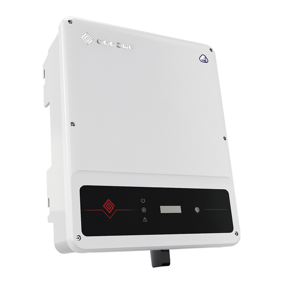
SDT8~15KW Figure 3.3.1-1 1. PV input terminals 3. Com Model 6. Indicator lights (SDT12~15KW PV *3pair) 4. AC output terminal 7. Button To allow dissipation of heat, and for convenience of dismantling, clearnaces around the 2. DC Switch (Optional) 5. Fan inverter must be at least: Figure 3.2.1-2 The installation position shall not prevent access to the disconnection means. -
Page 5: Electrical Connection
Inverter model Recommended circuit breaker specifications (2) Add breaker or fuse to AC side, the specification should be more than 1.25 times of rated AC GW4K-DT / GW5K-DT / GW6K-DT output current. GW8K-DT / GW10K-DT (3) The PE line of inverter should be connected the earth, make sure the impedance of neutral wire and earth wire less than 10ohm. - Page 6 DC Cable specification is showed as Figure 3.4.2-2. instruction can be referred to Wi-Fi Configuration in the accessory box. After configuration, please browse http://www.goodwe-power.com to create PV station. 3.4.6 Power Limiting Device & DRED Installation Connection method of Power Limiting device Meter please refer to Figure 3.4.6-1.
- Page 7 Remote shutdown and DRED: You need to connect 5 and 6 pins with a resistor to use "DRED " function ( for Australia ) or connecting 4 and 5 pins to use "Remote Shutdown" function ( for Europe ) , you can't use both DRED of them at the same time.
-
Page 8: System Operation
4 System Operation display an error message. Refer to Table 4.3. Through key operation, the screen can display different information such as operation 4.1 Indicator Lights parameters and power generation status in this area. There are two levels of menus, and the flow chart of first level menu is shown below: (3) Use of the display There are 2 modes of button operation: short press and long press. - Page 9 The records include error massage and error times(190520 15:30). Error massage can Second Level menu First Level menu Normal Long press 2S be Found in Table 4.3. 50Hz GridDefault Pac=6000W • View model name and reconfigure safety country: Short press E-Today= 15.2KWh Long press 2S Lock...
-
Page 10: Error Message
If the inverters is connected to the grid, “ Checking XXs ” will be The methods document of using the software can download from goodwe website or contact displayed and a countdown will commence from 30 seconds. when it shows “ 00S ”you with after sales. -
Page 11: Troubleshooting
5 Troubleshooting 6 Technical Parameters In most situations, the inverter requires very little maintenance. However, if the inverter is not Technical Data GW4K-DT GW5K-DT GW6K-DT GW8K-DT working properly, please try the following troubleshooting solutions; PV Input Data • When a problem occurs, the red (fault) LED indicator on the front panel will light up and the... -
Page 12: Certificates
Note: Technical Data GW10KT-DT GW12KT-DT GW15KT-DT Overvoltage category definition PV Input Data Category I: applies to equipment connected to a circuit where measures have been taken to Max. DC Power (W) 15000 18000 22500 reduce transient overvoltage to a low level. Max.
Need help?
Do you have a question about the GW4K-DT and is the answer not in the manual?
Questions and answers