Advertisement
Table of Contents
- 1 Table of Contents
- 2 Data
- 3 Unpacking Boiler
- 4 Pre-Installation and Boiler Mounting
- 5 Venting
- 6 Condensate Disposal
- 7 Water Piping and Trim
- 8 Gas Piping
- 9 Electrical
- 10 System Start-Up
- 11 Operation
- 12 Service and Maintenance
- 13 Troubleshooting
- 14 Service Parts
- 15 Above 2,000 Ft
- Download this manual
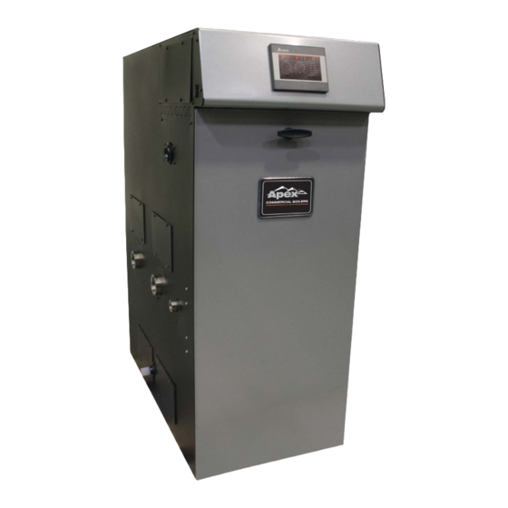
APEX
Installation, Operating and Service Instructions for
Commercial
Models:
• APX425C
• APX525C
• APX625C
• APX725C
• APX825C
Manual Contents
1. Product Description, Specifications & Dimensional
Data . . . . . . . . . . . . . . . . . . . . . . . . . . . . . . . . . . . . . . . .4
2. Unpacking Boiler . . . . . . . . . . . . . . . . . . . . . . . . . . . . .8
3. Pre-Installation and Boiler Mounting . . . . . . . . . . . . .8
4. Venting . . . . . . . . . . . . . . . . . . . . . . . . . . . . . . . . . . . .14
5. Condensate Disposal . . . . . . . . . . . . . . . . . . . . . . . .39
6. Water Piping and Trim . . . . . . . . . . . . . . . . . . . . . . . .41
7.
Gas Piping . . . . . . . . . . . . . . . . . . . . . . . . . . . . . . . . .53
8. Electrical . . . . . . . . . . . . . . . . . . . . . . . . . . . . . . . . . . .58
9. System Start-up . . . . . . . . . . . . . . . . . . . . . . . . . . . . .68
10. Operation . . . . . . . . . . . . . . . . . . . . . . . . . . . . . . . . . .77
11. Service and Maintenance . . . . . . . . . . . . . . . . . . . 115
12. Troubleshooting . . . . . . . . . . . . . . . . . . . . . . . . . . .121
13. Service Parts . . . . . . . . . . . . . . . . . . . . . . . . . . . . . .136
Appendix A: Instructions for High Altitude Installations
Above 2,000 ft. . . . . . . . . . . . . . . . . . . . . . . . . . . . . . . . .150
Improper installation, adjustment, alteration, service or maintenance can cause property damage, injury, or
death. For assistance or additional information, consult a qualified installer, service agency or the gas supplier.
This boiler requires a special venting system. Read these instructions carefully before installing.
106308-05 - 3/23
TM
Page
!
WARNING
Condensing
High Efficiency
Direct Vent
Gas-Fired
Water Boiler
9700609
Advertisement
Table of Contents

Related Manuals for Thermal Solutions APEX APX425C


Summary of Contents for Thermal Solutions APEX APX425C
-
Page 1: Table Of Contents
APEX Installation, Operating and Service Instructions for Condensing High Efficiency Direct Vent Commercial Gas-Fired Water Boiler Models: • APX425C • APX525C • APX625C • APX725C • APX825C Manual Contents Page 1. Product Description, Specifications & Dimensional Data . - Page 2 APEX Installation, Operating, & Service Instructions IMPORTANT INFORMATION - READ CAREFULLY NOTE: The equipment shall be installed in accordance with those installation regulations enforced in the area where the installation is to be made. These regulations shall be carefully followed in all cases. Authorities having jurisdiction shall be consulted before installations are made.
- Page 3 APEX Installation, Operating, & Service Instructions Special Installation Requirements for Massachusetts A. For all sidewall horizontally vented gas fueled equipment installed in every dwelling, building or structure used in whole or in part for residential purposes and where the sidewall exhaust vent termination is less than seven (7) feet above grade, the following requirements shall be satisfied: 1.
-
Page 4: Data
APEX Installation, Operating, & Service Instructions Product Description, Specifications and Dimensional Data Apex Series boilers are condensing high efficiency per Section 4 ‘Heating Boilers’ of ASME Boiler and gas-fired direct vent hot water boilers designed for Pressure Vessel Code, which provide a maximum heat transfer and simultaneous protection against use in forced hot water space or space heating with indirect domestic hot water heating systems, where... - Page 5 APEX Installation, Operating, & Service Instructions Product Description, Specifications and Dimensional Data (continued) 106308-05 - 3/23...
- Page 6 APEX Installation, Operating, & Service Instructions Product Description, Specifications and Dimensional Data (continued) 106308-05 - 3/23...
- Page 7 APEX Installation, Operating, & Service Instructions Product Description, Specifications and Dimensional Data (continued) 106308-05 - 3/23...
-
Page 8: Unpacking Boiler
Thermal Solutions DOES NOT warrant failures caused by mis-sized boiler applications. DO NOT oversize the boiler to the system. Multiple boiler installations greatly reduce the likelihood of boiler oversizing. - Page 9 APEX Installation, Operating, & Service Instructions Pre-Installation and Boiler Mounting (continued) F. The boiler should be located so as WARNING to minimize the length of the vent system. Asphyxiation Hazard. Locate combustion air pipe termination away Apply supplied dielectric grease to gasket from areas that may contaminate combustion inside vent connector.
- Page 10 APEX Installation, Operating, & Service Instructions Pre-Installation and Boiler Mounting (continued) WARNING Boiler Clearances to Combustible (and Non- Combustible) Material: Asphyxiation Hazard. Models APX425C and APX525C: Adequate combustion and ventilation air must be provided to assure proper combustion. Install These boilers are listed for closet installation with the combustion air intake per Section 4 “Venting”.
- Page 11 APEX Installation, Operating, & Service Instructions Pre-Installation and Boiler Mounting (continued) Figure 3-3: Clearances To Combustible and Non-combustible Material H. Boiler Stacking Installation & Boiler Mounting” of the manual for details. Always position higher input 1. For installations with unusually high space boiler model as bottom boiler.
- Page 12 APEX Installation, Operating, & Service Instructions Pre-Installation and Boiler Mounting (continued) a. Venting - Top and bottom boilers must d. Position the upper boiler on top of the have their individual vent piping and vent bottom boiler and align boiler front doors terminals.
- Page 13 APEX Installation, Operating, & Service Instructions Pre-Installation and Boiler Mounting (continued) 106308-05 - 3/23...
-
Page 14: Venting
APEX Installation, Operating, & Service Instructions Venting WARNING Asphyxiation Hazard. • Failure to vent this boiler in accordance with these instructions could cause products of combustion to enter the building resulting in severe property damage, personal injury or death. • Do not use a barometric damper, draft hood or vent damper with this boiler. - Page 15 APEX Installation, Operating, & Service Instructions Venting (continued) least equal to the rating of adjoining floor or b. Maintain minimum clearance to combustible ceiling. materials. See Table 3-2 for details. Note: For one or two family dwellings, fire c. Enclose vent passing through occupied resistance rating requirement may not need or unoccupied spaces above boiler with to be met, but is recommended.
- Page 16 APEX Installation, Operating, & Service Instructions Venting (continued) Table 4-2: Vent and Combustion Air Pipe Sizes and Equivalent Lengths (Applies to All Listed Vent/Combustion Air System Options) Combustion Air Length Vent Length Boiler Approx. Derate at Max. Option Pipe Dia., in. Min., ft.
- Page 17 APEX Installation, Operating, & Service Instructions Venting (continued) 106308-05 - 3/23...
- Page 18 APEX Installation, Operating, & Service Instructions Venting (continued) Les chaudières de catégories I, II et IV g. For multiple boiler installations with vertical doivent présenter des tronçons horizontaux roof terminals, separate vent pipes from dont la pente montante est d’au moins 1/4 multiple boilers may be piped through a po par pied (21 mm/m) entre la chaudière et common conduit or chase so that one roof...
- Page 19 APEX Installation, Operating, & Service Instructions Venting (continued) Figure 4-7: Direct Vent - Sidewall Snorkel Terminations Figure 4-8: Direct Vent - Sidewall Low Profile Termination nuisance shutdowns. If not, boiler may e. Do not install vent terminal directly above be installed with roof vent terminal and windows or doors.
- Page 20 APEX Installation, Operating, & Service Instructions Venting (continued) i. Maintain minimum clearance of at least l. Maintain minimum 12 in. (300 mm) 4 ft. (1.2 m) [3 ft. (900 mm) in Canada] horizontal spacing between vent terminal horizontally between vent terminal and gas and a building corner.
- Page 21 APEX Installation, Operating, & Service Instructions Venting (continued) boiler rear panel and insert vent connector B. CPVC/PVC Venting into heat exchanger vent outlet. WARNING b. Align vent connector plate and gasket clearance holes with rear panel Asphyxiation Hazard. engagement holes. Be sure combustion •...
- Page 22 Schedule 40 PVC Pipe x 6 in. (150 mm) min. horizontal run Schedule 40 PVC Pipe x 9 in. (230 mm) min. horizontal run Table 4-13: Components Required for Optional Ipex Low Profile Sidewall Termination Thermal Solutions Description Ipex Part Number...
- Page 23 APEX Installation, Operating, & Service Instructions Venting (continued) Figure 4-15: Field Installation CPVC/PP/SS Vent Connector Figure 4-16: Near-Boiler Vent/Combustion Air Piping Vent Piping b. Design the vent system to allow 3/8 in. (9.5 mm) of thermal expansion per 10 ft. Running PVC vent pipe inside (3.0 m) of CPVC/PVC pipe.
- Page 24 PVC Vent Pipe in. (1680 mm) from the boiler as Wall thimbles for CPVC/PVC pipe measured along the vent are available from Thermal Solutions: The wall is 12 in. (300 mm) thick P/N’s 102180-01 (3 in.), 102181-01 (4 or less in.), 103419-01(6 in.).
- Page 25 APEX Installation, Operating, & Service Instructions Venting (continued) Combustion Air Piping • After penetrating wall, install a Schedule 40 PVC 90° elbow so that elbow leg is in the up direction. • Install maximum vertical run of 7 ft. (2.1 m) of Schedule 40 PVC vent pipe.
- Page 26 APEX Installation, Operating, & Service Instructions Venting (continued) WARNING Asphyxiation Hazard. Combustion Air Piping • If possible, locate combustion Apply supplied dielectric grease to gasket air termination on the same roof inside vent section of vent connector. Failure to location as the vent termination to apply the grease could result in flue gas leaks prevent nuisance boiler shutdowns.
- Page 27 APEX Installation, Operating, & Service Instructions Venting (continued) 1/4 to 5/8 in. (6 mm to 16 mm) per joint to allow for iv. Push and twist adapter into vent system thermal expansion. connector until adapter bottoms out. 4. Terminations Tighten clamp to secure adapter in CPVC/PP/SS vent connector.
- Page 28 APEX Installation, Operating, & Service Instructions Venting (continued) 106308-05 - 3/23...
- Page 29 APEX Installation, Operating, & Service Instructions Venting (continued) a. Models APX425C and APX525C are listed for vertical venting by installing flexible vent in an UNUSED masonry chimney/chase and supplying combustion air through a separate wall or roof combustion air terminal. b.
- Page 30 APEX Installation, Operating, & Service Instructions Venting (continued) h. When there is a conflict between flexible polypropylene pipe (liner) manufacturer installation instructions and Apex boiler Installation, Operating and Service Instructions, the more restrictive instructions shall govern. Figure 4-27: Locking Band Clamp Installation, M&G DuraVent or Centrotherm InnoFlue Figure 4-25: Field Installation of Polypropylene Vent Adapter...
- Page 31 APEX Installation, Operating, & Service Instructions Venting (continued) Venting of Other Appliances (or Fireplace) into Chase or Adjacent Flues Prohibited! Figure 4-29: Flexible Vent in Masonry Chimney with Separate Combustion Air Intake 106308-05 - 3/23...
- Page 32 For use on models APX425C and APX525C, Single Wall Thimble 100184-01 Thermal Solutions offers size 4 in. vent pipe * Note: when using room air for combustion, use tee for and fittings shown in Table 4-30. It is the sidewall vent termination.
- Page 33 APEX Installation, Operating, & Service Instructions Venting (continued) Table 4-32: Z-Flex, Z-Vent (SVE Series III, Z-Vent III) Stainless Steel Vent System Components, Single Wall Sidewall * or Roof Termination: Boiler Model Nominal Pipe Diameter Boiler Adapter Wall Thimble Straight Termination w/Screen APX425C (reduced dia.
- Page 34 APEX Installation, Operating, & Service Instructions Venting (continued) Combustion Air Termination i. Vent Termination • After penetrating wall, install a 90° • Use components listed in Table 4-30, elbow so that the elbow leg is in the 4-31 or 4-32. up direction.
- Page 35 APEX Installation, Operating, & Service Instructions Venting (continued) 3. Terminations WARNING a. For standard horizontal sidewall Sources of combustion air contaminants, terminations, see Figures 4-6 and 4-7. When including chlorines, chlorofluorocarbons (CFC’s), using room air for combustion, use 90° petroleum distillates, detergents, volatile vapors elbow or tee for sidewall vent termination.
- Page 36 APEX Installation, Operating, & Service Instructions Venting (continued) 5. Faire fonctionner le brùleur principal pendant 6. After it has been determined that each 5 min ensuite, déterminer si le coupe-tirage appliance remain ing connected to the common déborde à l’ouverture de décharge. Utiliser la venting system properly vents when tested as flamme d’une allumette ou d’une chandelle ou outlined above, return doors, win dows, exhaust...
- Page 37 APEX Installation, Operating, & Service Instructions Venting (continued) c. Do not exceed the individual boiler f. Multiple individual boiler vertical vent pipes maximum vent length listed in Table 4-2. may be piped through a common conduit or d. For horizontal sidewall terminations, chase so that one roof penetration may be maintain at least 12 in.
- Page 38 APEX Installation, Operating, & Service Instructions Venting (continued) 106308-05 - 3/23...
-
Page 39: Condensate Disposal
APEX Installation, Operating, & Service Instructions Condensate Disposal A. Condensate Trap and Drain Line 6. Install tee for condensate overflow and vent as shown in Figure 5-2. 1. All condensate which forms in the boiler or vent system collects in the sump under heat WARNING exchanger and leaves the boiler through Asphyxiation Hazard. - Page 40 APEX Installation, Operating, & Service Instructions Condensate Disposal (continued) Figure 5-2: Condensate Trap and Drain Line B. Condensate Neutralizer Installation 3. Limestone chips will get coated by neutral salts (product of chemical reaction between 1. Some jurisdictions may require that the limestone and acidic condensate) and lose condensate be neutralized before being neutralizing effectiveness over time.
-
Page 41: Water Piping And Trim
Oxygen contamination of boiler water will cause corrosion of iron and steel boiler components, and can lead to boiler failure. Thermal Solutions’ Standard Warranty does not cover problems caused by oxygen contamination of boiler water or scale (lime) build-up caused by frequent addition of water. - Page 42 APEX Installation, Operating, & Service Instructions Water Piping and Trim (continued) Table 6-2: Flow Switch Paddle Application Space heating plus indirect water heater(s) – refer to Tables 6-4 and 6-5 Flow Switch Boiler and Figure 6-10 “Near Boiler Piping - Paddle Marking Heating Plus Indirect Water Heater”...
- Page 43 APEX Installation, Operating, & Service Instructions Water Piping and Trim (continued) Table 6-3: Flow Range Requirement Through Boiler DT= 35°F ΔT = 30°F ΔT = 25°F ΔT = 20°F Supply Return Boiler Boiler Minimum Required Boiler Required Boiler Maximum Boiler Connection Connection Head...
- Page 44 APEX Installation, Operating, & Service Instructions Water Piping and Trim (continued) Figure 6-6: Factory Supplied Piping and Trim Installation - APX525C, APX625C, APX725C and APX825C C. Standard Installation Requirements The end of the discharge pipe must terminate Observe the following guidelines when making the in an unthreaded pipe.
- Page 45 An optional manual reset external high limit is heat exchanger failure in accordance with available from Thermal Solutions to meet local requirements of ASME Boiler and Pressure code requirements. Vessel Code, Section IV, and ANSI/ASME CSD- 8.
- Page 46 APEX Installation, Operating, & Service Instructions Water Piping and Trim (continued) Table 6-8: Fitting and Valve Equivalent Length Table 6-8: Fitting and Valve Equivalent Length (continued) Copper Fitting and Sweat Valve Equivalent Length (ft.) Threaded Fitting and Valve Equivalent Length (ft.) Copper Pipe or Valve Size Fitting or Valve Black Threaded Pipe or...
- Page 47 APEX Installation, Operating, & Service Instructions Water Piping and Trim (continued) 106308-05 - 3/23...
- Page 48 APEX Installation, Operating, & Service Instructions Water Piping and Trim (continued) 106308-05 - 3/23...
- Page 49 APEX Installation, Operating, & Service Instructions Water Piping and Trim (continued) D. Special Situation Piping Installation such as the pump and expansion tank, must Requirements be designed for use in oxygenated water. 2. Piping with a Chiller - If the boiler is used Observe the following guidelines when making the in conjunction with a chiller, pipe the boiler actual installation of the boiler piping for special...
- Page 50 APEX Installation, Operating, & Service Instructions Water Piping and Trim (continued) Figure 6-13: Isolation of the Boiler From Oxygenated Water with A Plate Heat Exchanger (IWH Piped Off System Header) E. Multiple Boiler Water Piping 3. For installations where indirect domestic hot water heater is combined with space heating, 1.
- Page 51 APEX Installation, Operating, & Service Instructions Water Piping and Trim (continued) NOTICE: Installing a low water cutoff in the system piping of multiple boilers is strongly recommended and may be required by local codes. Figure 6-16: Multiple Boiler Water Piping w/Domestic Hot Water Heater (Page 1 of 2) 106308-05 - 3/23...
- Page 52 APEX Installation, Operating, & Service Instructions Water Piping and Trim (continued) NOTICE: Installing a low water cutoff in the system piping of multiple boilers is strongly recommended and may be required by local codes. Figure 6-16, continued: Multiple Boiler Water Piping w/Domestic Hot Water Heater (Page 2 of 2) 106308-05 - 3/23...
-
Page 53: Gas Piping
APEX Installation, Operating, & Service Instructions Gas Piping pressure may be less; contact gas supplier for WARNING additional information. Minimum gas valve inlet pressure is printed on the rating label located Explosion Hazard. in the boiler’s vestibule compartment. Failure to properly pipe gas supply to boiler may 2. - Page 54 APEX Installation, Operating, & Service Instructions Gas Piping (continued) Table 7-4: Specific Gravity Correction Factors For materials or conditions other than those listed Specific Correction Specific Correction above, refer to National Fuel Gas Code, ANSI Gravity Factor Gravity Factor Z223.1/NFPA 54 or Natural Gas and Propane 0.60 1.00 0.90...
- Page 55 APEX Installation, Operating, & Service Instructions Gas Piping (continued) WARNING Explosion Hazard. • Failure to use proper thread compounds on all gas connectors may result in leaks of flammable gas. • Gas supply to boiler and system must be absolutely shut off prior to installing or servicing boiler gas piping.
- Page 56 APEX Installation, Operating, & Service Instructions Gas Piping (continued) C. Pressure Test 2. The low gas pressure switch must be reset after the boiler is piped to the gas supply and See Table 7-6 for Apex Min./Max. Pressure before it is fired. Ratings.
- Page 57 APEX Installation, Operating, & Service Instructions Gas Piping (continued) E. Gas Piping for Multiple Boiler Installation CAUTION If gas pressure in the building is above ½ psig 1. Individual module (boiler) gas pipe sizing specific (3.4 kPa), an additional gas pressure regulator details - see Paragraph A.
-
Page 58: Electrical
APEX Installation, Operating, & Service Instructions Electrical DANGER Electrical Shock Hazard. Positively assure all electrical connections are unpowered before attempting installation or service of electrical components or connections of the boiler or building. Lock out all electrical boxes with padlock once power is turned off. - Page 59 APEX Installation, Operating, & Service Instructions Electrical (continued) Figure 8-2: PCB Locations for Field Wiring Figure 8-3: 120 VAC Field Wiring 106308-05 - 3/23...
- Page 60 APEX Installation, Operating, & Service Instructions Electrical (continued) 3. 24 VAC low voltage connections are located on NOTICE: When making low voltage connections, left side of right PCB and are shown in Figure make sure that no external power source is 8-4.
- Page 61 APEX Installation, Operating, & Service Instructions Electrical (continued) Figure 8-5: Ladder Diagram 106308-05 - 3/23...
- Page 62 APEX Installation, Operating, & Service Instructions Electrical (continued) Figure 8-6: Wiring Connections Diagram 106308-05 - 3/23...
- Page 63 APEX Installation, Operating, & Service Instructions Electrical (continued) Figure 8-7: Modified Wiring For DHW Priority When Using Low Flow Circulator Piped Off System Header - Heating (with Central Heating Circulators) Plus Alternately Piped Indirect Water Heater 106308-05 - 3/23...
- Page 64 APEX Installation, Operating, & Service Instructions Electrical (continued) 106308-05 - 3/23...
- Page 65 APEX Installation, Operating, & Service Instructions Electrical (continued) 106308-05 - 3/23...
- Page 66 APEX Installation, Operating, & Service Instructions Electrical (continued) 106308-05 - 3/23...
- Page 67 APEX Installation, Operating, & Service Instructions Electrical (continued) 106308-05 - 3/23...
-
Page 68: System Start-Up
APEX Installation, Operating, & Service Instructions Electrical (continued) F. Multiple Boiler Wiring b. Ethernet Cables 1. Install over-current protection in accordance Ethernet cables are used to connect the with authority having jurisdiction or, in the boiler network together. These are standard absence of such requirements, follow the “straight through”... - Page 69 APEX Installation, Operating, & Service Instructions System Start-up (continued) 3. Once a system is cleaned, use of an inhibitor F. Check all Gas Piping for Leaks and purge is also recommended such as the following or an piping sections that are filled with air. Refer to equivalent: National Fuel Gas Code, ANSI Z223.1/NFPA 54 or, ·...
- Page 70 APEX Installation, Operating, & Service Instructions System Start-up (continued) Figure 9-1: Operating Instructions 106308-05 - 3/23...
- Page 71 APEX Installation, Operating, & Service Instructions System Start-up (continued) L. Upon Initial Start-up, Gas Train Will be WARNING Filled with Air Any gas valve adjustments (throttle and/ or offset) specified herein and subsequent Even if the gas line has been completely purged combustion data (%O , %CO , CO air free ppm)
- Page 72 APEX Installation, Operating, & Service Instructions System Start-up (continued) Figure 9-4: Burner Flame WARNING e. If low fire O is too low (CO is too high), Make sure that all adjustments at high fire are increase O (decrease CO ) by turning offset screw counterclockwise in less than made with the throttle, not offset screw (see Figure 9-5).
- Page 73 APEX Installation, Operating, & Service Instructions System Start-up (continued) WARNING 2. Test the flow switch by disabling the primary Explosion Hazard. Asphyxiation Hazard. loop circulator. The boiler must not start if flow is not present. This conversion should be performed by a qualified service agency in accordance with the 3.
- Page 74 APEX Installation, Operating, & Service Instructions System Start-up (continued) 1. Fully close throttle by turning throttle screw WARNING clockwise until it fully stops. Asphyxiation Hazard. 2. Open throttle screw counter-clockwise the The throttle adjustments shown in Table 9-6 are number of full (360 degrees) and partial turns approximate.
- Page 75 APEX Installation, Operating, & Service Instructions System Start-up (continued) WARNING Asphyxiation Hazard. • If the throttle is very far out of adjustment on the “rich” (counter-clockwise) side, the boiler burner may be running at 0% excess air or even with air deficiency. Operating the boiler in this condition may cause property damage, personal injury or death.
- Page 76 APEX Installation, Operating, & Service Instructions System Start-up (continued) Table 9-10: Control Parameter Checklist Parameter Step Parameter Description Location Select appropriate source: Not Installed, Wired, Wireless, or Outdoor Sensor Source Modbus. Adjust >> Warm Weather System Selecting Enable will restrict boiler start during warm Shutdown Enable/ weather, but only if an outdoor sensor is installed.
-
Page 77: Operation
APEX Installation, Operating, & Service Instructions Operation on outside air temperature, time of day, and length of demand (boost) settings for energy savings. Outdoor reset requires installation of A. Basic Operation an outdoor sensor. Hard-wired and wireless When a call for heat is provided, the boiler outdoor sensors are available. - Page 78 APEX Installation, Operating, & Service Instructions Operation (continued) heating cycle. C. Supply (Outlet) Water Temperature 5. Boost Time Regulation When the Central Heat Setpoint is decreased 1. Priority Demand by Outdoor Reset settings, the Boost function can be enabled to increase the setpoint in the When more than one demand is present, the event that central heat demand is not satisfied higher priority demand is used to determine...
- Page 79 APEX Installation, Operating, & Service Instructions Operation (continued) 6. Ignition Failure Additionally, a soft lockout occurs if the supply The control monitors ignition using a burner temperature rises to fast (i.e. faster than the mounted flame sensor. Response on ignition degrees Fahrenheit per second limit).
- Page 80 APEX Installation, Operating, & Service Instructions Operation (continued) Figure 10-3: Home Screen Figure 10-2: Limit String Status Screen Showing Central Heat Demand Table 10-4: Limit String Limit String Description Action Type “ON” indicates heat demand and enables control to fire to maintain water temperature at setpoint. •...
- Page 81 APEX Installation, Operating, & Service Instructions Operation (continued) 2. MAIN MENU provides access to all display functions. It is accessible from the Home Screen. The following major user interface areas are accessed from the Main Menu: a. STATUS provides a “walk” through of boiler operation.
- Page 82 APEX Installation, Operating, & Service Instructions Operation (continued) Table 10-8: Hydronic System Parameter and Factory Setting Range/Choices Description Never, Any Demand Central Heat, OFF DHW Demand Boiler Pump Any Demand Header Sensor Demand/ Combustion air Damper Never Any Demand System Pump Any Demand Central Heat, No Priority Central Heat, Optional Priority, Fresh Air Damper...
- Page 83 APEX Installation, Operating, & Service Instructions Operation (continued) Figure 10-12: Sequence of Operation G. Sequence of Operation Boiler status is shown in the lower right corner of the Home Screen (see Figure 10-3). After limits have been established, the boiler sequence progresses as shown in Table 10-11 and Figure 10-12. Figure 10-13: Home Screen Details 106308-05 - 3/23...
- Page 84 APEX Installation, Operating, & Service Instructions Operation (continued) H. Status Screens 3. Demand Status Boiler status screens are the primary boiler This screen gives the demand status of monitoring screens. The user may simply “walk” the Central Heat, Domestic Hot Water, and through boiler operation by repeatedly selecting Sequencer (Lead Lag).
- Page 85 APEX Installation, Operating, & Service Instructions Operation (continued) Figure 10-15: Status Screen Detail 106308-05 - 3/23...
- Page 86 APEX Installation, Operating, & Service Instructions Operation (continued) I. Manual Operation and Tuning J. Parameter Adjustment 1. Entering Adjust Mode Select Main Menu >> Operation to access the Operation screen shown in Figure 10-16. From the Operation screen, the user may manually adjust NOTICE: Parameter adjustment may be firing rate or exercise pumps, access a service performed only by a qualified service technician.
- Page 87 APEX Installation, Operating, & Service Instructions Operation (continued) 2. Adjusting Parameters After entering the password, editing parameters is accomplished as follows: Figure 10-18: Adjusting Parameters 3. System Parameters Select to access the following parameters. Parameter and Description Factory Setting Range / Choices Temperature Units Fahrenheit, Fahrenheit...
- Page 88 APEX Installation, Operating, & Service Instructions Operation (continued) 3. System Parameters (continued) Parameter and Description Factory Setting Range / Choices Installer’s Password Allows for custom password to be set. Must be 9 characters or less. Only allows adjustment of supervisor password (supervisor default: 76). Cannot change factory password.
- Page 89 APEX Installation, Operating, & Service Instructions Operation (continued) 4. Modulation Parameters WARNING Asphyxiation Hazard. Boiler type is factory set and must match the boiler model. Only change the boiler type setting if you are installing the boiler at altitudes above 2,000 ft. or if you are replacing the control. The boiler type setting determines minimum and maximum blower speeds.
- Page 90 APEX Installation, Operating, & Service Instructions Operation (continued) 5. Pump Parameters Select to access the following parameters. Factory Parameter and Description Range / Choices Setting System Pump Activates system pump output according to selected function: Never Never: Pump is disabled and not shown on status screen. Any Demand: Pump runs for any demand.
- Page 91 APEX Installation, Operating, & Service Instructions Operation (continued) 6. Example Pump Parameter Selections Single boiler, No Indirect Water Heater Parameter Selections: System Pump= “any demand” Boiler Pump = “any demand” DHW Modulation Sensor = “DHW Sensor” DHW Pump = “never” Explanation: This piping arrangement only services central heat.
- Page 92 APEX Installation, Operating, & Service Instructions Operation (continued) Multiple Boilers, Boiler Piped Indirect Water Heater Sequencer Master Boiler 2 (Boiler 1) Wiring locations: Enable/Disable DHW Demand System pump DHW pump Boiler Pump Sequencer Master Parameter Selections: Sequencer Master Enabled Indirect Water “Boiler Piped”...
- Page 93 APEX Installation, Operating, & Service Instructions Operation (continued) Example Pump Parameter selections (continued) Multiple Boilers, Primary Piped Indirect Water Heater, System Pump Run for Any Demand Sequencer Master Boiler 2 (Boiler 1) Wiring locations: Enable/Disable DHW Demand System pump DHW pump Boiler Pump Sequencer Master Parameter Selections: Sequencer Master...
- Page 94 APEX Installation, Operating, & Service Instructions Operation (continued) 8. Central Heat Parameters Select to access the following parameters. Parameter and Description Factory Setting Range / Choices Central Heat Setpoint 180°F 50 to 190°F Target temperature for the central heat priority. Value also used by the outdoor air (82.2°C) (10 to 87.8°C) reset function.
- Page 95 APEX Installation, Operating, & Service Instructions Operation (continued) Table 10-20: Response Speed Adjustment Guidelines-20 9. Domestic Hot Water Parameters Select to access the following parameters. Parameter and Description Factory Setting Range / Choices Priority Time When Priority Time is greater than zero and Domestic Hot Water (DHW) heat demand is “on”, DHW demand will take “Priority”...
- Page 96 APEX Installation, Operating, & Service Instructions Operation (continued) 9. Domestic Hot Water Parameters, continued Parameter and Description Factory Setting Range / Choices DHW Modulation Sensor Outlet Sensor: Boiler modulates for DHW demand in response to supply/outlet Outlet Sensor, sensor in boiler. Outlet Sensor DHW Sensor: Boiler modulates for DHW demand in response to DHW sensor at...
- Page 97 APEX Installation, Operating, & Service Instructions Operation (continued) 10. Outdoor Reset Parameters Select to access the following parameters. Factory Range / Parameter and Description Setting Choices Outdoor Reset Enable If an outdoor sensor is installed and Outdoor Reset is Enabled, the boiler will automatically adjust the heating set point temperature based on the outdoor reset curve in (see Figure 10-21).
- Page 98 APEX Installation, Operating, & Service Instructions Operation (continued) 11. Sequencer Master NOTICE: Enable only one Sequencer Master boiler within a group of networked boilers. Erratic behavior will result if more than one Sequencer Master is enabled. Select to access the following parameters. Factory Parameter and Description Range / Choices...
- Page 99 APEX Installation, Operating, & Service Instructions Operation (continued) 12. Sequencer Slave Select to access the following parameters. Parameter and Description Factory Setting Range / Choices Boiler Address Each boiler must be given a unique address. When Slave Selection Order is set to None 1 to 8 Use Normal Order, the boiler address is used by the Sequence Master as the boiler...
- Page 100 APEX Installation, Operating, & Service Instructions Operation (continued) 14. Tune Select to access the following parameters. Select to access the following parameters. Parameter and Description Factory Setting Range / Choices Response Speed Adjusts Central Heat temperature control Proportion Integral Derivative (PID) values.
- Page 101 APEX Installation, Operating, & Service Instructions Operation (continued) Select to access the following parameters. Parameter and Description Factory Setting Range / Choices Response Speed Adjusts Domestic Hot Water temperature control Proportion Integral Derivative (PID) values. A higher value causes a larger firing rate change per degree of requested temperature change.
- Page 102 APEX Installation, Operating, & Service Instructions Operation (continued) Select to access the following parameters. Parameter and Description Factory Setting Range / Choices Fan Speed-Up Ramp 0 to 12,000 rpm Maximum fan ramp rate when fan speed is increasing. Fan Speed-Down Ramp 0 to 12,000 rpm Maximum fan ramp rate when fan speed is decreasing.
- Page 103 APEX Installation, Operating, & Service Instructions Operation (continued) K. USB Thumb Drive Parameter Transfer Load Parameters from USB Loads the current saved parameter settings A USB port is provided on left side of boiler from a USB drive. Parameter files must display panel.
- Page 104 APEX Installation, Operating, & Service Instructions Operation (continued) Table 10-22: Parameters Summary (continued) Table 10-22: Parameters Summary (continued) Parameter Security Parameter Security Load/Save Load/Save PUMPS SEQUENCER SLAVE System Pump Supervisor Slave Selection Order Supervisor Boiler Pump Supervisor Boiler Address Supervisor DHW Pump Supervisor LIMITS...
- Page 105 APEX Installation, Operating, & Service Instructions Operation (continued) L. Multiple Boiler Control Sequencer 1. Setup NOTICE: Enable only one Sequencer Master boiler within a group of networked boilers. Erratic behavior will result if more than one Sequencer Master is enabled. Assign all boilers a unique address. Undesirable simultaneous operation occurs when two boilers’...
- Page 106 APEX Installation, Operating, & Service Instructions Operation (continued) Setpoint Base Load Rate Default 40% Range (25 – 100%) Slow Load Fast Change Load Change Start Start Stop Stop Stop Start Lead Boiler Lead Boiler Figure 10-24: Multiple Boiler Sequence Diagram (3 boiler system shown, typical for up to 8 boilers) Optimized Boiler Modulation Multiple Demands...
- Page 107 APEX Installation, Operating, & Service Instructions Operation (continued) Backup Header Sensor o Enable/Disable – Upon loss of Sequencer Master, each boiler will If the header sensor fails, the Sequencer automatically begin local control. Master uses the lead boiler’s supply sensor to This means it will operate only if it control firing rate.
- Page 108 APEX Installation, Operating, & Service Instructions Operation (continued) M. Energy Management System (EMS) Interface The control system has a fully featured ability to interface with an Energy Management System (EMS). The control system allows remote control and monitoring via RS485 Modbus or through direct wiring. The following sections outline setup of the EMS interface and adjustable EMS interface parameters.
- Page 109 APEX Installation, Operating, & Service Instructions Operation (continued) 3. Modbus Setup Parameters Select to bring up the following sub-menu. Select to view and/or adjust COM port parameters as needed to communicate with an EMS. Follow on screen instructions. COM 1 is used for communication between touch screen display and the boiler control and does not require adjustment.
- Page 110 APEX Installation, Operating, & Service Instructions Operation (continued) 4. Modbus Register List A list of available Modbus registers and descriptions is stored in the display and provided in Table 10-26. To access Select to access the list of available Modbus registers. Table 10-26: Modbus Register List ENABLE/DISABLE Modbus...
- Page 111 APEX Installation, Operating, & Service Instructions Operation (continued) Table 10-26: Modbus Register List (continued) SETPOINTS Modbus Protocol Read (R) / Description Register Name Write (W) 0=Unknown, 1=Normal setpoint, 2=TOD setpoint, 410065 CH setpoint source 3=Outdoor reset, 4=Remote control (4-20mA ), 7=Outdoor reset time of day -40 F (-40°C) to 266°F (130°C) 410016...
- Page 112 APEX Installation, Operating, & Service Instructions Operation (continued) Table 10-26: Modbus Register List (continued) TEMPERATURE SENSORS Modbus Protocol Read (R) / Description Register Name Write (W) 410007 Supply sensor -40 F (-40°C) to 266 F (130°C) 410011 Return sensor -40 F (-40°C) to 266 F (130°C) 410013 Header sensor -40 F (-40°C) to 266 F (130°C)
- Page 113 APEX Installation, Operating, & Service Instructions Operation (continued) Table 10-26: Modbus Register List (continued) TROUBLESHOOTING Modbus Protocol Read (R) / Description Register Name Write (W) Reasons for burner lockout No lockout, Supply high limit DHW high limit Stack High limit Flame detected out of sequence Lightoff rate proving failed Purge rate proving failed...
- Page 114 APEX Installation, Operating, & Service Instructions Operation (continued) Table 10-26: Modbus Register List (continued) PUMP STATUS Modbus Protocol Read (R) / Description Register Name Write (W) 400096 CH pump status See Table 10-27. 400100 DHW pump status See Table 10-27. 400108 Boiler pump status See Table 10-27.
-
Page 115: Service And Maintenance
APEX Installation, Operating, & Service Instructions Service and Maintenance Important Product Safety Information: Refractory Ceramic Fiber Product WARNING Some boiler components use materials that contain refractory ceramic fibers (RCF). RCF has been classified as a possible human carcinogen. When exposed to elevated temperatures, RCF may change into crystalline silica, a known carcinogen. - Page 116 APEX Installation, Operating, & Service Instructions Service and Maintenance (continued) WARNING • Asphyxiation Hazard. This boiler requires regular maintenance and service to operate safely. Follow the instructions contained in this manual. • Improper installation, adjustment, alteration, service or maintenance can cause property damage, personal injury or death.
- Page 117 APEX Installation, Operating, & Service Instructions Service and Maintenance (continued) DANGER Explosion Hazard. Electrical Shock Hazard. Burn Hazard. • This boiler uses flammable gas, high voltage electricity, moving parts, and very hot water under high pressure. Assure that all gas and electric power supplies are off and that the water temperature is cool before attempting any disassembly or service.
- Page 118 APEX Installation, Operating, & Service Instructions Service and Maintenance (continued) brush. Any cleaning of the combustion chamber WARNING with acid or alkali products is prohibited. Do not Electrical Shock Hazard. use any cleaning agents or solvents. If insulation disc has signs of damage, it must be replaced. Label all wires prior to disconnection when servicing controls.
- Page 119 Avenue, Altoona, PA 16602, Tel: systems. Use of ethylene glycol could result in (972) 547-6002 and/or selected HVAC property damage, personal injury or death. distributors. Contact Thermal Solutions for specific details. E. Condensate Overflow Switch and iii. Sentinel X400 System Restorer (For ®...
- Page 120 APEX Installation, Operating, & Service Instructions Service and Maintenance (continued) 2. Condensate Trap Removal and Reinstallation: Switch Removal and Replacement procedure above. a. Disconnect power supply to boiler. j. Ensure that fresh silicon sealant is applied to b. Remove 2 wire nuts and disconnect overflow the overflow switch threads and the switch is switch wire pigtails from boiler wiring.
-
Page 121: Troubleshooting
APEX Installation, Operating, & Service Instructions Troubleshooting A. Help Menu Navigation WARNING When a fault is active, the Help icon flashes Electrical Shock Hazard. red on the Home Screen. See Figure 12-1. To Turn off power to boiler before working on investigate a fault, select Help. - Page 122 APEX Installation, Operating, & Service Instructions Troubleshooting (continued) B. Troubleshooting when Help icon NOT flashing: Indication Condition Possible Cause Boiler not responding to • Boiler not seeing Enable/Disable or DHW Demand input. Check wiring demand. Status and Priority Demand not for loose connections or miswiring.
- Page 123 APEX Installation, Operating, & Service Instructions Troubleshooting (continued) C. Soft Lockout (Hold) From the Help menu, select the blinking Soft Lockout (Hold) icon to determine the cause of the soft lockout. See Figure 12-2. The boiler will automatically restart once the condition that caused the lockout is corrected. Figure 12-2: Example Soft Lockout The Soft Lockout (Hold) screen will display the hold number, name, condition that caused the hold, possible causes, and a basic description of corrective actions that may be taken to fix the problem.
- Page 124 APEX Installation, Operating, & Service Instructions Troubleshooting (continued) Table 12-3: Soft Lockout (Hold) Codes (continued) Lockout Condition Possible Cause Number Shorted or open return temperature • Shorted or miswired return sensor wiring Return Sensor sensor. • Defective return sensor Fault Shorted or open supply •...
- Page 125 APEX Installation, Operating, & Service Instructions Troubleshooting (continued) D. Hard Lockout From the Help menu, select the blinking Hard Lockout icon to determine the cause of the hard lockout. See Figure 12-4. The boiler will automatically restart once the condition that caused the lockout is corrected. Figure 12-4: Example Hard Lockout The Hard Lockout screen will display the lockout number, name, condition that caused the lockout, possible causes, and a basic description of corrective actions that may be taken to fix the problem.
- Page 126 APEX Installation, Operating, & Service Instructions Troubleshooting (continued) Table 12-5: Hard Lockout Codes (continued) Lockout Condition Possible Cause Number • Reversed flow through boiler. Verify correct piping and circulator orientation. Return Return temperature was greater • No boiler water flow. Verify system is purged of air and Temperature than supply temperature for at least appropriate...
- Page 127 APEX Installation, Operating, & Service Instructions Troubleshooting (continued) Table 12-5: Hard Lockout Codes (continued) Lockout Condition Possible Cause Number Air proving switch closed before Prepurge. Interrupted Air proving switch failed to open. • Failed air proving switch. Check switch for proper operation. Airflow •...
- Page 128 APEX Installation, Operating, & Service Instructions Troubleshooting (continued) E. Limit String Status From the Help Menu, select Limit String Status to view status of individual safety limits. See Figure 12-6. ON indicates closed limit contact. OFF with red background indicates open limit contact. When a limit is OFF, all limits connected to the same control terminal (e.g.
- Page 129 APEX Installation, Operating, & Service Instructions Troubleshooting (continued) Table 12-8: Sensor Fault Diagnostic Help Indication Possible Cause Sensor has not been selected. For example, in Figure 12-7, the Header Sensor has not been Not Installed selected. Refer to Operations Section, Parameter Adjustment for information on how to select sensors.
- Page 130 APEX Installation, Operating, & Service Instructions Troubleshooting (continued) Table 12-11: Outdoor Sensor Table 12-12: Header Sensor Temperature vs. Resistance, Temperature vs. Resistance, 10kOhm NTC, Beta = 3435K 10kOhm NTC, Beta = 3950K Outdoor Temperature Temperature Ohms of Ohms of Resistance Resistance °F °C...
- Page 131 APEX Installation, Operating, & Service Instructions Troubleshooting (continued) G. Additional Help Menu Icons A summary of additional icons that may be flashing on the Help Menu is provided in Table 12-13. WARNING Asphyxiation Hazard. Boiler type is factory set and must match the boiler model. Only change the boiler type setting if you are installing the boiler at altitudes above 2,000 ft.
- Page 132 APEX Installation, Operating, & Service Instructions Troubleshooting (continued) H. Archives Select Archives from the Main Menu to view boiler historic boiler operating data. See Figure 12-14. Archives allow user to review up to four months of sensor values, up to 3,000 alarms, lockout history, and cycle and run time history.
- Page 133 APEX Installation, Operating, & Service Instructions Troubleshooting (continued) 3. Cycle & Run Time History Cycle and Run time data is provided for control, boiler and pumps. Additionally, a load profile is collected. Graphs are provided that show amount of time the boiler operated at each load point. Data may be reset. See Figure 12-17.
- Page 134 APEX Installation, Operating, & Service Instructions Troubleshooting (continued) Figure 12-19: Example USB Drive File Path Figure 12-20 shows an example of the Trend1-20141022.csv file contents. Boiler state is defined in Table 12-22. Figure 12-21 shows an example of the Alarm-20140612.csv file contents. Figure 12-20: Example Trend File Contents 106308-05 - 3/23...
- Page 135 APEX Installation, Operating, & Service Instructions Troubleshooting (continued) Figure 12-21: Example Alarm File Contents Table 12-22: Boiler State Boiler State Initiate Standby delay Standby Safe Startup Drive Purge Prepurge Drive Lightoff Preignition Test Preignition PFEP (pilot flame establishing period) MFEP (main flame establishing period) Direct Ignition Running Postpurge...
-
Page 136: Service Parts
All Apex Repair Parts may be obtained through your local authorized Thermal Solutions representatives or outlets. Should you require assistance in locating a Thermal Solutions representative or outlet in your area, or have questions regarding the availability of Thermal Solutions products or repair parts, please contact Thermal Solutions Customer Service at (717) 239-7642 or Fax (877) 501-5212. - Page 137 APEX Installation, Operating, & Service Instructions Service Parts (continued) 106308-05 - 3/23...
- Page 138 APEX Installation, Operating, & Service Instructions Service Parts (continued) Heat Exchanger Components Part Number Description APX425C APX525C APX625C APX725C APX825C Replacement Heat Exchanger Assembly (includes bare heat exchanger, supply and return water temperature 109102-01 109103-01 109104-01 109105-01 sensors, air vent valve and water gaskets) 1A Air Vent Valve 108760-01 1B Supply Water Temperature Sensor / High Limit Sensor...
- Page 139 APEX Installation, Operating, & Service Instructions Service Parts (continued) 106308-05 - 3/23...
- Page 140 APEX Installation, Operating, & Service Instructions Service Parts (continued) Blower / Gas Train Components Part Number Description APX425C APX525C Replacement Blower Kit (includes blower, blower outlet gasket and hardware) 104999-01 104999-02 Blower Outlet Gasket 106209-01 109208-01 Blower Inlet Assembly (includes gas orifice, injector flange, inlet shroud (425C 110037-01 110038-01 only), swirl plate, blower adapter plate, and mounting hardware)
- Page 141 APEX Installation, Operating, & Service Instructions Service Parts (continued) 106308-05 - 3/23...
- Page 142 APEX Installation, Operating, & Service Instructions Service Parts (continued) Blower / Gas Train Components Part Number Description APX625C APX725C APX825C Replacement Blower Kit (includes blower, blower outlet gasket 104999-03 and hardware) Blower Outlet Gasket 109223-01 Natural Gas: Natural Gas: Blower Inlet Assembly (includes gas orifice, injector flange, inlet 110041-01 110042-01 shroud (425 only), swirl plate, blower adapter plate, and mounting...
- Page 143 APEX Installation, Operating, & Service Instructions Service Parts (continued) Condensate Trap and Related Components Part Number Description APX425C APX525C APX625C APX725C APX825C Replacement Condensate Trap Kit (includes trap, float switch, grommet, coupling, and 109111-01 110044-01 clamps) Replacement Condensate Float Switch Kit 105005-01 (includes float switch and clamp) Spring Hose Clamp, 15/16 in.
- Page 144 APEX Installation, Operating, & Service Instructions Service Parts (continued) Control Components Part Number Description APX425C APX525C APX625C APX725C APX825C Replacement Control Kit (programmed) 106499-01 106499-02 Replacement Display Kit (programmed, includes 106507-01 mounting hardware) Display Power Supply 105994-01 Transformer 106034-01 109220-01 Replacement 120V PCB Kit (includes PCB, fuses, 106512-01 and hardware)
- Page 145 APEX Installation, Operating, & Service Instructions Service Parts (continued) 106308-05 - 3/23...
- Page 146 APEX Installation, Operating, & Service Instructions Service Parts (continued) Jacket and Trim Components Part Number Description APX425C APX525C APX625C APX725C APX825C Left Side Panel 106249-01 106249-02 106249-03 106249-04 Right Side Panel (includes rating label instructions) 106517-01 106517-02 106517-03 106517-04 Top Panel (includes gaskets) 106254-01 106254-02 106254-03...
- Page 147 Additional Components Part Number Description APX425C APX525C APX625C APX725C APX825C CSD-1 Kit (not shown, includes gas pressure switches) 106056-01 107421-01 Contact Thermal Solutions for LP boilers Gas Pressure Switch Assembly 109205-01 Low Gas Pressure Switch 109191-01 High Gas Pressure Switch 109190-01...
- Page 148 APEX Installation, Operating, & Service Instructions Service Parts (continued) 106308-05 - 3/23...
- Page 149 APEX Installation, Operating, & Service Instructions Service Parts (continued) Wiring Harnesses Part Number Description APX425C APX525C APX625C APX725C APX825C 10A 120V Harness 109193-01 10B Low Voltage Harness 109201-01 10C Fan Power Harness 109198-01 10D Ignition Harness 109192-01 10E USB Harness 106001-01 10F Delta Display Power Harness 106006-01...
-
Page 150: Above 2,000 Ft
APEX Installation, Operating, & Service Instructions Appendix A Instructions for High Altitude Installations Above 2,000 ft. WARNING • If installing APX525C or APX725C: Do not convert APX525C to LP gas (propane) at altitudes above 6,000 ft. Also, do not install APX725C LP gas (propane) at altitudes above 7,800 ft. Attempts to do so may result in unreliable operation, property damage, personal injury or death due to carbon monoxide (CO air free) poisoning. - Page 151 APEX Installation, Operating, & Service Instructions Appendix A Instructions for High Altitude Installations Above 2,000 ft. (continued) 8. If low fire CO is too low, increase CO Start-up Instructions for Natural Gas or LP turning offset screw clockwise in less than 1/8 1.
- Page 152 APEX Installation, Operating, & Service Instructions Appendix A Instructions for High Altitude Installations Above 2,000 ft. (continued) Table A-4: Apex Altitude Adjustments Percentage Derate Altitude Model Fuel Recommended CO Range (approx. per 1,000 ft.) 8.6-9.2 APX425C 2.3% 9.4-10.2 8.7-9.2 APX525C 4.1% 9.8-10.1 8.6-9.2...
- Page 153 APEX Installation, Operating, & Service Instructions Figure Page Description Number Number Section 1 - Product Description, Specifications & Dimensional Data Figure 1-3 Apex - Model APX425C Figure 1-4 Apex - Model APX525C Figure 1-5 Apex - Models APX625C, APX725C, and APX825 Section 3 - Pre-Installation and Boiler Mounting Figure 3-3 Clearances To Combustible and Non-combustible Material...
- Page 154 APEX Installation, Operating, & Service Instructions Page Figure Number Description Number Section 7 - Gas Piping Figure 7-5 Recommended Gas Piping Figure 7-7 Gas Inlet Pressure Tap and Pressure Switch Location Section 8 - Electrical Figure 8-2 PCB Locations for Field Wiring Figure 8-3 120 VAC Field Wiring Figure 8-4...
- Page 155 APEX Installation, Operating, & Service Instructions Figure Page Description Number Number Section 12 - Troubleshooting Figure 12-1 Help Menu Navigation Figure 12-2 Example Soft Lockout Figure 12-4 Example Hard Lockout Figure 12-6 Limit String Status Figure 12-7 Sensors Screen with Shorted Supply Sensor Figure 12-14 Archives Screen Figure 12-15...
- Page 156 Listed Polypropylene Pipe, Fittings and Terminations - Centrotherm Eco Table 4-24 Listed Polypropylene Pipe, Fittings and Terminations - Z-Flex Z-Dens Table 4-30 Thermal Solutions (Heat Fab) Vent System Components (Stainless Steel, 4 in. only) Table 4-31 M&G Dura FasNSeal Stainless Steel Vent Systems Components, Single Wall Table 4-32...
- Page 157 APEX Installation, Operating, & Service Instructions Table Page Description Number Number Section 7 - Gas Piping (continued) Table 7-1 Maximum Capacity of Schedule 40 Black Pipe in CFH* (Natural Gas) For Gas Pressures of 1/2 psi (3.4 kPa) or Less Table 7-2 Maximum Capacity of Schedule 40 Black Pipe in CFH* (LP Gas) For Gas Pressures of 1/2 psig (3.4 kPa) or Less...
- Page 158 APEX Installation, Operating, & Service Instructions Table Page Description Number Number Section 12 - Troubleshooting (continued) Table 12-11 Outdoor Sensor Temperature vs. Resistance, 10kOhm NTC, Beta = 3435K Table 12-12 Header Sensor Temperature vs. Resistance, 10kOhm NTC, Beta = 3950K Table 12-13 Additional Help Menu Icons Table 12-22...
- Page 159 If any part of a commercial grade boiler or any part or accessory provided by Thermal Solutions is found to be defective in material or workmanship during this one year period, Thermal Solutions will, at its option, repair or replace the defective part (not including labor).
- Page 160 APEX Installation, Operating, & Service Instructions Thermal Solutions, LLC P.O. Box 3244 Lancaster, PA 17604 1-888-432-8887 www.thermalsolutions.com 106308-05 - 3/23...
Need help?
Do you have a question about the APEX APX425C and is the answer not in the manual?
Questions and answers