Thermal Solutions AMP 1000 Installation, Operation And Maintenance Manual

Thermal Solutions AMP 1000 Installation, Operation And Maintenance Manual

Table of Contents

Advertisement

Quick Links

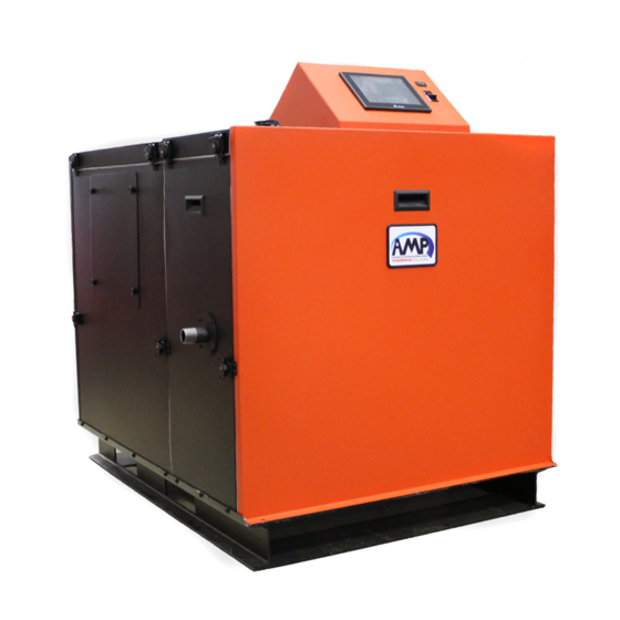
INSTALLATION, OPERATION,
AND MAINTENANCE MANUAL
Heating Boiler Models
AMP 1000
AMP 1250
AMP 1500
AMP 2000
Model: ______________________________________________
Serial Number: ______________________________________________
Installation Date: ______________________________________________
: __________________________________________
Heating Contractor
Thermal Solutions Products, LLC
Phone: 717-239-7642
Hot Water Supply
Boiler Models
AMP 2500
AMPW 2500
AMP 3000
AMPW 3000
AMP 3500
AMPW 3500
AMP 4000
AMPW 4000
1175 Manheim Pike, Lancaster, PA 17601
Save this manual for future reference.
WARNING: If the information in these
instructions is not followed exactly, a fire
or explosion may result causing property
damage, personal injury or death.
Do not store or use gasoline or other
flammable vapors and liquids in the vicinity
of this or any other appliance.
WHAT TO DO IF YOU SMELL GAS
• Do not try to light any appliance.
• Do not touch any electrical switch; do
not use any phone in your building.
• Immediately call your gas supplier
from a neighbor's phone. Follow the
gas supplier's instructions.
• If you cannot reach your gas supplier,
call the fire department.
Installation and service must be performed
by a qualified installer, service agency or the
gas supplier.
Email: orders@thermalsolutions.com
PN: 108588-01
REV. 6
www.thermalsolutions.com

Advertisement

Table of Contents
loading

Summary of Contents for Thermal Solutions AMP 1000

  • Page 1 Serial Number: ______________________________________________ Installation and service must be performed Installation Date: ______________________________________________ by a qualified installer, service agency or the : __________________________________________ Heating Contractor gas supplier. Thermal Solutions Products, LLC www.thermalsolutions.com Phone: 717-239-7642 1175 Manheim Pike, Lancaster, PA 17601 Email: orders@thermalsolutions.com...
  • Page 2: Table Of Contents

    Table of Contents I. Hazard Definitions II. Read Before Proceeding Local Codes Warranty Shipment Damage Connecting Gas Supply Line Appliance Operation Gas Leakage (If you detect or smell gas...) Maintenance Freeze Protection Fluids Product Identification Label Factory Test and Inspections Disclaimers and Local Codes III. Product Rating, Specifications, and Dimensional Data IV. AMP Component Identification V. Unpacking The AMP...
  • Page 3 Table of Contents Temperature Rise and Heat Exchanger Head Loss Standard Piping Components Water Quality and Treatments Oxygen Contamination X. Heating Boiler Piping diagrams XI. Hot Water Supply Boiler Water Piping General Piping Guidelines Factory Supplied Outlet Manifold (AMPW) Standard Piping Components Scalding Water Quality Temperature Rise and Heat Exchanger Head Loss...
  • Page 4: Hazard Definitions

    I. Hazard Definitions The following terms are used throughout this manual to bring attention to the presence of hazards of various risk levels, or to important information concerning product life. It is critical all personnel read and adhere to all information contained in DANGER, WARNING, and CAUTIONS. All DANGERS, WARNINGS, and CAUTIONS are for reference and guidance purpose, and, therefore, do not substitute for strict adherence to applicable jurisdictional and professional codes and regulations.
  • Page 5: Read Before Proceeding

    II. Read Before Proceeding A. Local Codes 2. Do not block or restrict in any way the flow of combustion or ventilation air from or to the 1. This unit shall be installed in accordance with those appliance installation regulations enforced in the area where 3.
  • Page 6: Factory Test And Inspections

    II. Read Before Proceeding (continued) J. Factory Test and Inspections 1. Prior to shipment, final air-fuel adjustments are WARNING WARNING performed by factory trained service personnel on each appliance. The factory emissions report This product can expose you to chemicals, is posted on the back of the front jacket panel as including chromium, which are known to the state a reference for troubleshooting and maintenance.
  • Page 7: Product Rating, Specifications, And Dimensional Data

    III. Product Rating, Specifications, and Dimensional Data boilers are not designed for use in gravity hot water space AMP Series boilers are condensing, high-efficiency, gas- heating systems or systems containing significant amount fired, hot water boilers designed for use in forced hot of dissolved oxygen (swimming pool water heating, direct water or heating with indirect domestic hot water heating domestic hot water heating, etc.).
  • Page 8 III. Product Rating, Specifications, and Dimensional Data (continued) Table 3: Product Dimensions AMP Model Dimensions (in.) 1000 1250 1500 2000 2500 3000 3500 4000 45-1/2 45-1/2 66-1/8 66-1/8 75-5/8 75-5/8 97-1/8 97-1/8 72-1/2 74-5/8 83-3/4 83-3/4 105-1/8 105-1/8 55-7/8 55-7/8 76-1/2 76-1/2 86-1/2 86-1/2...
  • Page 9 III. Product Rating, Specifications, and Dimensional Data (continued) SUPPLY NOZZLE RETURN NOZZLE GAS TRAIN CONNECTION SUPPLY NOZZLE LIFTING LUGS RETURN NOZZLE (Z-COG) (Y-COG) DRAIN VENT AIR SUPPLY (Z-COG) (X-COG) 1" CONDENSATE DRAIN Figure 1: AMP Boiler Dimensions...
  • Page 10: Amp Component Identification

    IV. AMP Component Identification 1. Communication Interface (Concert Boiler Control) The AMP series is equipped with the Concert Boiler Control display which provides easy access for viewing and adjusting operational parameters and alarms/lockouts, and monitoring historical performance characteristics. 2. Main appliance control It receives and processes input signals from safety switches and sensors to modulate the burner firing rate.
  • Page 11 IV. AMP Component Identification (continued) 16. Inlet/Return water connection Inlet connection that returns water from the system to the boiler. Refer to Table 3 for model specific pipe connection sizes. 17. Supply/outlet water temperature sensor Dual element temperature sensor for high limit and modulation control. 18.
  • Page 12 IV. AMP Component Identification (continued) Figure 2: Component Identification...
  • Page 13 IV. AMP Component Identification (continued) Figure 3: Component Identification...
  • Page 14: Unpacking The Amp

    V. Unpacking The AMP A. Unpacking and Inspection 1. Move appliance to approximate installation WARNING WARNING location. 2. Remove all crate fasteners. Failure to assure the truck forks are long enough 3. Lift and remove outside container. to extend at least half way through the base will result in the appliance tipping off the lift truck 4.
  • Page 15: Pre-Installation And Mounting

    (see Table 4). In accelerated component failure. particular, avoid areas near chemical products Thermal Solutions DOES NOT warrant failures containing chlorines, chlorofluorocarbons, paint caused by mis-sized appliance applications. DO removers, cleaning solvents, and detergents. Avoid NOT oversize the appliance to the system.
  • Page 16: Appliance Mounting

    VI. Pre-Installation and Mounting (continued) B. Appliance Mounting 1. The AMP is intended for installation in an area with Table 4: Corrosive Combustion Air Contaminants a floor drain, or in a suitable drain pan to prevent Contaminants to Avoid: any leaks or safety relief valve discharge resulting in property damage.
  • Page 17: Clearances

    VI. Pre-Installation and Mounting (continued) C. Clearances NOTICE NOTICE 1. The AMP is approved for 0" clearance to combustible materials. The clearances for serviceability are This appliance is approved for zero inch clearance found in Table 5. to combustible or noncombustible material, but 2.
  • Page 18: Venting

    5. For flue gas venting, have horizontal runs sloping Common venting with other manufacturers' upwards not less than ¼ inch per foot (21 mm/m) appliances or different Thermal Solutions models from the boiler to the vent terminal. is prohibited. 6. This appliance operates under conditions that permit condensation in the heat exchanger and the flue gas venting.
  • Page 19: General Termination

    VII. Venting (continued) C. General Termination 13. For multiple appliance installations with vertical roof terminals, separate vent pipes may be piped 1. Use only listed vent/combustion air terminals. through a common conduit for chase so that one 2. Follow the termination configurations shown in roof penetration may be made.
  • Page 20: Field Installation

    VII. Venting (continued) 14. Maintain minimum 12 in. (300 mm) horizontal spacing between vent terminal and a building corner. 15. Under certain conditions, water in the flue gas may condense, and possibly freeze, on objects around the terminal including on the structure itself. If these objects are subject to damage by flue gas condensate, they should be moved or protected.
  • Page 21 VII. Venting (continued) Table 6: Vent and Combustion Air Pipe Diameters and Maximum Lengths Combustion Air Length Vent Length Pipe Dia. Minimum Maximum Pipe Dia. Minimum Maximum Model in. (mm) ft. (m) ft. (m) in. (mm) ft. (m) ft. (m) 8 (200) 150 (45.7) 8 (200) 3 (0.9)
  • Page 22 VII. Venting (continued) Table 9: Recommended Venting Configurations and Material Options Vent & Intake Vent Penetration Reference Termination Parts Table Materials Option Through Structure Figure Intake Horizontal Sidewall Tee or elbow Figure 8 Vent Horizontal Sidewall Tee or straight Two Pipe Intake Horizontal Sidewall Tee or elbow...
  • Page 23 *Factory supplied flue connection. Adapters are required to transition to alternate vent materials or manufacturers. Table 12: Stainless Steel and CPVC Vent Adapters Stainless Steel to CPVC Heat Fab to Z-Vent Vent Diameter (in.) Thermal Solutions Part # Z-Flex Part # 109510-01 2SVSHF08 109510-02 2SVSHF10...
  • Page 24 VII. Venting (continued) Table 13: Stainless Steel Vent and Intake Terminations Vent Heat Fab Part # Z-Flex Part # Style Model Diameter (in.) Saf-T Vent Z-Vent 1000 9890TEE 2SVST08 1250 Elbow 9814TERM 2SVEE0890 1500 2000 Straight 9892 2SVSTPX08 91090TEE 2SVST10 2500 Elbow 91014TERM 2SVEE1090...
  • Page 25 VII. Venting (continued) Figure 5: Direct Vent Terminal Clearances Figure 6: Other than Direct Vent Terminal Clearances...
  • Page 26 VII. Venting (continued) Table 16: Direct Vent Terminal Clearances Canadian Installations US Installations Clearance above grade, veranda, 12 in (30 cm) 12 in (30 cm) porch, deck, or balcony 6 in (15 cm) for appliances ≤ 6 in (15 cm) for appliances 10,000 Btuh (3 kW), 12 in (30 ≤...
  • Page 27 VII. Venting (continued) Table 17: Other than Direct Vent Terminal Clearances Canadian Installations US Installations Clearance above grade, veranda, 12 in (30 cm) 12 in (30 cm) porch, deck, or balcony 6 in (15 cm) for appliances ≤ 10,000 Btuh (3 kW), 12 in (30 4 ft (1.2 m) below or to side of Clearance to window or door that cm) for appliances >...
  • Page 28: Vent And Combustion Air Terminals

    VII. Venting (continued) E. Vent and Combustion Air Terminals 1. Vent Piping NOTICE NOTICE Methods of securing and sealing terminals to a. Install fire stops where vent passes through the outside wall must not restrain the thermal floors, ceilings or framed walls. The fire stop expansion of the vent pipe.
  • Page 29 VII. Venting (continued) BRACE VENT TERMINAL (IF REQUIRED) COMBUSTION AIR TERMINAL STORM COLLAR FLASHING Extend vent/combustion air piping to maintain minimum vertical (‘X’) and minimum horizontal (‘Y’) distance of 12 in. (300 mm) [18 in. (460 mm) Canada] from roof surface. Allow additional vertical (‘X’) distance for expected snow accumulation.
  • Page 30: Terminal Installation

    VII. Venting (continued) NOTICE NOTICE F. Terminal Installation The joint between the terminal and the last 1. Use the terminal connections supplied by the venting manufacturer. Follow manufacturer’s piece of pipe must be outside of the building. instructions to attach the terminal to the vent Use 90°...
  • Page 31: Polypropylene Venting

    VII. Venting (continued) G. Polypropylene Venting WARNING WARNING 1. Running Flexible Polypropylene Vent (Liner) Through Unused Chimney Chase Asphyxiation Hazard. Vent systems made by listed a. It is the responsibility of the installing contractor PP vent system manufacturers rely on gaskets for to procure polypropylene vent system pipe and proper sealing.
  • Page 32 VII. Venting (continued) NOTICE NOTICE Pressure drop for flexible polypropylene line is 20 % greater than from rigid pipe. Multiply measured flexible polypropylene liner length by 1.2 to obtain equivalent length. Maximum equivalent vent length of flexible polypropylene liner is 48 ft. (14.6 m). WARNING WARNING DO NOT mix vent systems of...
  • Page 33: Optional Room Air For Combustion

    VII. Venting (continued) H. Optional Room Air for Combustion Motorized louvers or dampers must be interlocked 1. General Guidelines with the appliance to allow ignition and firing of the burner only when louvers are in the fully-open a. Room air is optional for commercial applications. position.
  • Page 34: Multiple Appliance Terminations

    VII. Venting (continued) I. Multiple Appliance Terminations For vertical roof terminations, maintain at least 12 in. (300 mm) minimum horizontal distance 1. Vent Piping Terminations between adjacent individual appliance vent a. Multiple appliance vent terminations are shown terminations. in Figure 12. 2.
  • Page 35: Removing Existing Appliance

    Thermal Solutions takes no responsibility for 7. Any improper operation of the common venting vent systems that create issues and or affect the system should be corrected so the installation performance of the appliance.
  • Page 36: Special Installation Requirements For Massachusetts

    VII. Venting (continued) K. Special Installation Requirements for Massachusetts 1. For all sidewall horizontally vented gas fueled equipment installed in every dwelling, building or structure used in whole or in part for residential purposes and where the sidewall exhaust vent termination is less than seven (7) feet above grade, the following requirements shall be satisfied: a.
  • Page 37: Condensate Disposal

    VIII. Condensate Disposal A. General B. Condensate trap installation 1. Note the following when disposing of the 1. Locate the condensate trap assembly shipped loose condensate: with this appliance. a. Condensate is slightly acidic, typical pH around 2. Install the condensate trap on the lower rear of the 3.5 - 4.5.
  • Page 38: Condensate Neutralizer Installation

    VIII. Condensate disposal (continued) WARNING WARNING C. Condensate Neutralizer Installation 1. Some jurisdictions may require that the condensate be neutralized before being disposed of. Follow local codes pertaining to condensate disposal. Failure to fill the condensate trap with water prior to start-up could cause flue gas to enter the 2.
  • Page 39: Hydronic Piping

    4 pipe diameter) and size a circulation pump that components, and can lead to boiler failure. ensures sufficient flow is maintained through the Thermal Solutions’ Standard Warranty does not boiler. cover problems caused by oxygen contamination a. The flow rate through the primary loop is of boiler water or scale (lime) build-up caused by maintained by the installer provided circulator.
  • Page 40: Temperature Rise And Heat Exchanger Head Loss

    XI. Water Piping (continued) D. Temperature Rise and Heat Exchanger Head Loss 1. The AMP heat exchanger adds pressure drop to the system which must be accounted for in the design of the piping configuration and pump selection. 2. For systems with glycol mixture, the flow rate specified in Table 20 will increase as specified in Table 24 due to the extra frictional loss introduced by the glycol.
  • Page 41: Standard Piping Components

    IX. Hydronic Piping (continued) WARNING WARNING E. Standard Piping Components 1. Safety Relief Valve (Required) The AMP Boiler is shipped with an installed Burn Hazard. Safety relief valve discharge shall pressure relief valve. be piped in such a way to prevent or eliminate a.
  • Page 42: Water Quality And Treatments

    IX. Hydronic Piping (continued) 10. Flow Control Valve (Strongly Recommended) NOTICE NOTICE The flow control valve prevents flow through the system unless the circulator is operating. Flow control valves are used to prevent gravity circulation in circulator zone systems through zones The AMP heat exchanger is made from stainless that are not calling for heat.
  • Page 43: Oxygen Contamination

    IX. Hydronic Piping (continued) NOTICE NOTICE b. The TDS (in ppm) is determined by measuring the electrical conductivity (µS/cm) of the water and multiplying by a conversion factor (typically 0.65 for drinking water). Water temperatures over 140 °F (60 °C) greatly increase the affects of corrosive chemicals.
  • Page 44 When using Glycol products, all Glycol manufacturers’ requirements, including rust inhibitors, must be adhered to. Maximum 50 % Glycol. Thermal Solutions' Standard Warranty does not cover boiler failure caused by oxygen contamination of boiler water or scale build-up.
  • Page 45: Heating Boiler Piping Diagrams

    X. Heating Boiler Piping diagrams Figure 16: Single Boiler, Primary/Secondary Piping Single AMP/BFIT Primary/Secondary Piping System Circulator To System Pressure Reducing Valve Isolation Valve Air Vent Purge Valve Make Up Water From System Factory Supplied Manifold Isolation Valve Expansion Tank Check Valve Boiler Circulator Y-Strainer No more than 12 inches or 4 pipe diameters...
  • Page 46 Thermal Solutions Products LLC ure drop across the entire boiler loop. 2. Pressure relief valve rating shall not exceed pressure rating of any component in the system.
  • Page 47 4. Circulation pump must be sized to overcome the pressure drop across the entire 3. The circulator shall be sized to overcome the loop. Thermal Solutions Products LLC pressure drop across the entire loop.
  • Page 48 2. Pressure relief valve shall not exceed the pressure rating of any components in the system. Make Up Water 3. The boiler pump shall be sized to overcome the Thermal Solutions Products LLC Purge Vavle DWH Circulator pressure drop across the entire boiler loop.
  • Page 49: Hot Water Supply Boiler Water Piping

    AMP in a hot water supply system. The installer is will cause corrosion of the steel components, and responsible for complying with local codes. can lead to appliance failure. Thermal Solutions’ 1. The cold water return line shall be connected to the Standard Warranty does not cover problems inlet of the appliance labeled "Return".
  • Page 50: Scalding

    XI. Hot Water Supply Boiler Piping (continued) WARNING WARNING b. The safety relief valve must be installed with the spindle in a vertical position. Installation of the relief valve must comply with ASME Boiler and Pressure Vessel Code, Section IV. Safety Relief Valve c.
  • Page 51: Water Quality

    XI. Hot Water Supply Boiler Piping (continued) DANGER DANGER a. Mixing valves can be installed at the outlet of storage tank or at other zones or fixtures in the system. 2. When appliances such as dishwashers or clothes washers are used in a domestic hot water system that require increased temperatures, two hot water supply's can be set up as shown in Figure 24.
  • Page 52: Temperature Rise And Heat Exchanger Head Loss

    XI. Hot Water Supply Boiler Piping (continued) NOTICE NOTICE Table 27: Water Quality Requirements The AMP heat exchanger is made from stainless Quality Parameter Minimum Maximum steel tubular double coil having relatively narrow Water Hardness (ppm) waterways. Once filled with water, it will be Total Dissolved Solids (ppm) subject to the effects of corrosion.
  • Page 53: Pump Selection

    XI. Hot Water Supply Boiler Piping (continued) G. Pump Selection A Circulation pump is a required component for complete installation of this appliance. Choosing the appropriate pump is critical for the functionality, safe operation, and longevity of the appliance. Pumps should be sized for each particular installation based on the required flow rate, water hardness, and total pressure drop in the primary loop between the tank and the boiler.
  • Page 54 1. These are suggested piping configurations. It is the installer's responsibility to The circulator shall be sized to overcome the conform to local codes and ordinances for additional requirements. Thermal Solutions Product ssure drop across the entire loop. 2. Pressure relief valve rating shall not exceed pressure rating of any component in the system.
  • Page 55 2. Relief valve shall not exceed the pressure rating of any components in the system. 3. The circulator shall be sized to overcome the Thermal Solutions Products LL pressure drop across the entire loop. 1. These are suggested piping configurations. It is the installer's responsibility to conform to local codes and ordinances for additional requirements.
  • Page 56 Relief valve shall not exceed the pressure ng of any components in the system. he circulator shall be sized to overcome the Thermal Solutions Products LLC ssure drop across the entire loop. 1. These are suggested piping configurations. It is the installer's responsibility to conform to local codes and ordinances for additional requirements.
  • Page 57 10" rating of any components in the system. 2000 6" 8" 10" 10" 10" 3. The circulator shall be sized to overcome the Thermal Solutions Prod pressure drop across the entire loop. 2500 8" 10" 10" 12" 12" 3000 8"...
  • Page 58 10" ating of any components in the system. . The circulator shall be sized to overcome the 2000 6" 8" 10" 10" 10" Thermal Solutions Products ressure drop across the entire loop. 2500 8" 10" 10" 12" 12" 3000 8"...
  • Page 59: Gas Piping

    XII. Gas Piping A. Guidelines and Requirements 10. If the high or low gas pressure switch tripped, it All installation must conform to the National Fuel must be manually reset before the appliance can Gas Code ANSI Z223.1/NFPA54, and/or local codes. be restarted.
  • Page 60 XII. Gas Piping (continued) Maximum capacity of schedule 40 black pipe in CFH* Table 31:  Natural Gas, Inlet Pressure 14.0 in wc (3.4 kPa)or less; 0.5 in wc (0.12 kPa) Pressure Drop Nominal Inside Length of Pipe (Ft) Pipe Size Diameter (In) (In)
  • Page 61 XII. Gas Piping (continued) WARNING WARNING Table 33: Specific Gravity Correction Factors Specific Correction Specific Correction Failure to properly pipe gas supply to appliance may Gravity Factor Gravity Factor result in improper operation and damage. Always 0.60 1.00 0.90 0.82 assure gas piping is absolutely leak free and of the 0.65 0.96 0.78...
  • Page 62: Electrical

    XIII. Electrical DANGER DANGER A. General Install wiring and electrically ground the appliance in accordance with authority having jurisdiction or, in the absence of such requirements, follow the National Electrical Shock Hazard: Ensure all electrical Electrical Code, NFPA 70, and/or Canadian Electrical connections are disconnected before attempting Code Part 1, CSA C22.1.
  • Page 63: Appliance Wiring

    XIII. Electrical (continued) C. Appliance Wiring c. Avoid placing senors near potential sources of electrical noise such as transformers, power lines, 1. Connect to field wiring inside the control box. . and fluorescent lighting. Wire the sensor to the I I nside the control box are five printed circuit boards appliance using 22 gauge or larger wire.
  • Page 64 XIII. Electrical (continued) Boiler must be grounded in accordance with ANSI National Electric Code. Connect to V/C/P Primary Power Supply To Grounding Fuses Ground Screw Conductor Blower Terminal Combustion Blower Power Fuses Fuses used for only 208 V and 230 V Transformer used for only 208 V and 230 V...
  • Page 65 XIII. Electrical (continued) Boiler must be grounded in accordance Connect to V/C/P with ANSI National Electric Code. Power Supply Primary To Grounding Fuses Ground Screw Conductor Blower Terminal Fuses Combustion Blower Power Transformer 120vac 24vac Continue to low Concert Boiler voltage circuit PCB-01 Control (A1167)
  • Page 66 XIII. Electrical (continued) PCB-01 (3A Slow Blow) PCB-05 Continue from high voltage circuit P4b-1 P18a-4 Central Heat P5-11 Concert Boiler 24vac Enable/ Control (A1167) J17/W1 Disable Input (STAT) J8-3 P5-8 P4b-2 P18a-3 J8-6 P5-2 P4b-4 P18a-2 Setpoint or Modulation J8-7 P5-1 P4b-3 P18a-1...
  • Page 67 XIII. Electrical (continued) Concert Boiler Control (A1167) PCB-02 F2 (6.3A Slow Blow) J4-6 P31-4 Power Supply (120 or 24 VAC) P31-5 J4-7 System Pump (Supplied by others) Spare F3 (6.3A Slow Blow) J4-4 P31-2 Power Supply (120 or 24 VAC) P31-6 J4-5 Boiler Pump/Circulator...
  • Page 68: System Start-Up

    XIV. System Start-up DANGER DANGER A. Check System Setup 1. Verify that the venting, water piping, gas piping and electrical system are installed properly. Refer to installation instructions contained in this manual. Do not use matches, candles, or other open flame ignition sources to check for leaks.
  • Page 69 XIV. System Start-up(continued) FOR YOUR SAFETY READ BEFORE OPERATING/P OUR VOTRE     SECURITE LISEZ AVANT DE METTRE EN MARCHE WARNING: If you do not follow these instructions exactly, a fire or explosion may result causing property damage, personal injury or loss of life. AVERTISSEMENT: Quiconque ne respecte pas à...
  • Page 70: Combustion Air/Fuel Adjustment

    XIV. System Start-up(continued) C. Combustion Air/Fuel Adjustment 6. Verify O (or CO ) and CO concentration are within limits specified in Table 37. Note: the values in For high fire adjustment this table are for sea level only. For high altitude a.
  • Page 71: Field Conversion Of Gas Type

    XIV. System Start-up(continued) WARNING WARNING D. Field Conversion of Gas Type This appliance is factory tested and set up for the gas type selected but can be field converted with the following steps. Make sure that all adjustments at high fire are 1.
  • Page 72: Pump Control

    XIV. System Start-up(continued) E. Pump Control H. Testing of Controls and Safety Devices Ensure the appropriate pump parameters are Prior to placing the appliance in operation, the selected in the Pumps menu of the Concert control. installing contractor or other responsible personnel Refer to the Concert Boiler Control manual for more must perform safety and control device limit tests information.
  • Page 73: Service And Maintenance

    XV. Service and Maintenance IMPORTANT PRODUCT SAFETY INFORMATION IMPORTANT PRODUCT SAFETY INFORMATION REFRACTORY CERAMIC FIBER PRODUCT REFRACTORY CERAMIC FIBER PRODUCT WARNING: The Repair Parts list designates parts that contain refractory ceramic fibers (RCF). RCF has been classified as a possible human carcinogen. When exposed to temperature above 1805 °F, such as during direct flame contact, RCF changes into crystaline silica, a know carcinogen.
  • Page 74: General Maintenance

    XV. Service and Maintenance WARNING WARNING A. General Maintenance 1. Keep the area around the appliance free from combustible materials. (Gasoline and other flammable vapors and liquids) Read and understand the entire manual before 2. Keep the area around the combustion air inlet attempting installation, start-up, operation, or terminal free from contaminants.
  • Page 75 XV. Service and Maintenance (continued) DANGER DANGER 2. Igniter Electrode a. Disconnect power to the unit and remove ignition electrode from the burner door. This appliance uses flammable gas, high voltage b. Visually inspect igniter assembly (ceramic electricity, moving parts, and very hot water under insulators, bracket, and graphite gasket) for high pressure.
  • Page 76 XV. Service and Maintenance (continued) WARNING WARNING a. Inspect ultra-violet (uv) scanner lens and remove any debris with a soft cloth. If condensate or fog is observed on the glass, Failure to properly secure the burner/blower/gas the gaskets may need to be replaced. valve assembly to the heat exchanger could lead to property damage, personal injury or loss of life.
  • Page 77: Restarting After Prolong Shutdown

    XV. Service and Maintenance (continued) b. Any accumulation of soot or debris should be thoroughly cleaned out. 6. Combustion air filter with air box a. Undo the latches on the filter box to lift the lid and access the filter. b.
  • Page 78: Appendix A: Tables

    APPENDIX A: Tables I. Hazard Definitions II. Read Before Proceeding III. Product Rating, Specifications, and Dimensional Data Table 1: AMP Boiler Ratings Table 2: AMP Specifications Table 3: Product Dimensions IV. AMP Component Identification V. Unpacking The AMP VI. Pre-Installation and Mounting Table 4: Corrosive Combustion Air Contaminants Table 5: Clearances for Serviceability VII. Venting Table 6: Vent and Combustion Air Pipe Diameters and Maximum Lengths Table 7: Equivalent lengths of Vent and Combustion Air Components...
  • Page 79: Appendix B: Figures

    APPENDIX B: Figures I. Hazard Definitions II. Read Before Proceeding III. Product Rating, Specifications, and Dimensional Data Figure 1: AMP Boiler Dimensions IV. AMP Component Identification Figure 2: Component Identification Figure 3: Component Identification V. Unpacking The AMP Figure 4: Lifting Lugs VI. Pre-Installation and Mounting VII. Venting Figure 5: Direct Vent Terminal Clearances Figure 6: Other than Direct Vent Terminal Clearances Figure 8: Horizontal Sidewall Termination Figure 7: Slopped Roof Termination...
  • Page 80: Appendix C: Default Light-Off And Modulation Rates

    APPENDIX C: Default Light-off and Modulation Rates AMP Model Parameter 1000 1250 1500 2000 2500 3000 3500 4000 Max Power MBTU 1000 1250 1500 2000 2500 3000 3500 4000 CH/DHW Max. Modulation Rate (RPM) 6200 7600 4600 4800 4500 5500 6200 6400 Minimum Modulation Rate (RPM) 1725...
  • Page 81: Appendix D: The Dual Gas Amp

    APPENDIX D: The Dual Gas AMP A. Dual Gas AMP: General D. Gas Selection 1. The dual Gas construction allows for two gases 1. The Dual Gas AMP features a gas selection (Natural/ (natural gas and propane gas) to be connected to Propane) switch that electrically separates the two the appliance at one time which allows for quick gas valves.
  • Page 82 APPENDIX D (continued) Gas Selection Switch Natural Gas Connection LP/Propane Connection High Gas Pressure Switch Low Gas Pressure Switch Gas Valves Low Gas Pressure Switch High Gas Pressure Switch...
  • Page 83 APPENDIX D (continued) Boiler must be grounded in accordance Connect to V/C/P with ANSI National Electric Code. Primary Power Supply Fuses To Grounding Ground Screw Conductor Blower Terminal Combustion Blower Power Fuses Fuses used for only 208 V and 230 V Transformer used for only 208 V and 230 V...
  • Page 84 APPENDIX D (continued) Boiler must be grounded in accordance Connect to V/C/P with ANSI National Electric Code. Power Supply Primary To Grounding Fuses L2 L3 Combustion Blower Power Ground Screw Conductor Blower Terminal Fuses Transformer 120vac 24vac Continue to low Concert Boiler voltage circuit PCB-01...
  • Page 85 Notes...
  • Page 86 This page is intentionally left blank.
  • Page 87 If a claim is made under this warranty during the “No Charge” period from the date of shipment, Thermal Solutions will, at its option, repair or replace the pressure vessel (not including labor).
  • Page 88 Thermal Solutions Product, LLC Lancaster, PA 17604-3244 Phone: 717-239-7642 orders@thermalsolutions.com www.thermalsolutions.com...

Table of Contents