Emerson Rosemount 2051CF Quick Start Manual
Hide thumbs
Also See for Rosemount 2051CF:
- Quick start manual (52 pages) ,
- Quick installation manual (21 pages) ,
- Quick start manual (28 pages)

Related Manuals for Emerson Rosemount 2051CF


Summary of Contents for Emerson Rosemount 2051CF
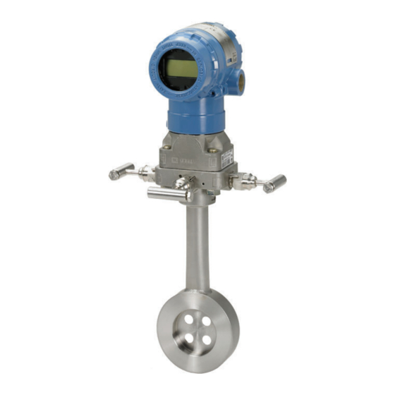
- Page 1 Quick Start Guide 00825-0600-4101, Rev CA March 2020 ™ Rosemount 2051 Pressure Transmitter and Rosemount 2051CF Series Flow Meter ™ with F Fieldbus Protocol OUNDATION...
-
Page 2: Table Of Contents
Quick Start Guide March 2020 Contents About this guide .......................... 3 System readiness......................... 5 Mount the transmitter........................7 Tagging............................14 Housing rotation........................15 Set the switches......................... 16 Wire, ground, and power up.......................18 Configure........................... 21 Zero trim the transmitter......................28 Product certifications......................... 29... -
Page 3: About This Guide
(I.S.) installations. Refer to Rosemount 2051 Reference Manual for more instructions. This guide is also available electronically at Emerson.com/Rosemount. Safety messages WARNING Explosions could result in death or serious injury. Installation of these transmitters in an explosive environment must be in accordance with the appropriate local, national, and international standards, codes, and practices. - Page 4 Quick Start Guide March 2020 WARNING Physical access Unauthorized personnel may potentially cause significant damage to and/or misconfiguration of end users’ equipment. This could be intentional or unintentional and needs to be protected against. Physical security is an important part of any security program and fundamental to protecting your system.
-
Page 5: System Readiness
DD4: DD Fieldbus.org Emerson.com 00809-0200- Rev 1 4101, Rev BA or DD5: DD Fieldbus.org newer Rev 1 Emerson AMS Device Emerson.com Manager V 10.5 or higher: DD Rev 2 Emerson AMS Device Emerson.com Manager V 8 to 10.5: DD Rev 1... - Page 6 Device Obtain at Device driver Reference revision driver (DTM) document (DD) Emerson 375/475: FieldCommun DD Rev 2 icator.com Fieldbus device revision can be read using a F Fieldbus OUNDATION OUNDATION capable configuration tool. Device driver file names use device and DD revision. To access functionality, the correct device driver must be installed on your control and asset management hosts, and on your configuration tools.
-
Page 7: Mount The Transmitter
March 2020 Quick Start Guide Mount the transmitter Liquid applications Procedure 1. Place taps to the side of the line. 2. Mount beside or below the taps. 3. Mount the transmitter so the drain/vent valves are oriented upward. Gas applications Procedure 1. - Page 8 Quick Start Guide March 2020 Steam applications Procedure 1. Place taps to the side of the line. 2. Mount beside or below the taps. 3. Fill impulse lines with water.
- Page 9 March 2020 Quick Start Guide Figure 3-1: Panel and Pipe Mounting Panel mount Pipe mount Coplanar flange Traditional flange Rosemount 2051T × 1 panel bolts are customer supplied. Quick Start Guide...
- Page 10 Use only bolts supplied with the transmitter or sold by Emerson as spare parts. Figure 3-2 illustrates common transmitter assemblies with the bolt length required for proper transmitter assembly.
- Page 11 March 2020 Quick Start Guide 3. Torque the bolts to the final torque value using the same crossing pattern. See Table 3-1 for final torque value. 4. Verify the flange bolts are protruding through the sensor module bolt holes before applying pressure. Table 3-1: Torque Values for the Flange and Flange Adapter Bolts Bolt material Head markings Initial torque Final torque...
- Page 12 Quick Start Guide March 2020 Figure 3-3: O-rings A. Flange adapter B. O-ring C. PFTE based D. Elastomer Note You should replace PTFE O-rings if you remove the flange adapter. Environmental seal for housing Thread sealing (PTFE) tape or paste on male threads of conduit is required to ®...
- Page 13 March 2020 Quick Start Guide Figure 3-4: In-line Gage Low Side Pressure Port A. Pressure port location Quick Start Guide...
-
Page 14: Tagging
The device description loaded in the host system must be at the same revision as this device. The device description can be downloaded from the by selecting Download host system website or Emerson.com/Rosemount Device Drivers under Product Quick Links. You can also visit Fieldbus.org select End User Resources. -
Page 15: Housing Rotation
March 2020 Quick Start Guide Housing rotation To improve field access to wiring or to better view the optional LCD display follow the procedure steps. Figure 5-1: Housing Rotation A. Housing rotation set screw (5/64 in.) Procedure 1. Loosen the housing rotation set screw using a 5/64 -in. hex wrench. 2. -
Page 16: Set The Switches
Quick Start Guide March 2020 Set the switches Set simulate and security switch configuration before installation as shown Figure 6-1. • The simulate switch enables or disables simulated alerts and simulated AI Block status and values. The default simulate switch position is enabled. - Page 17 March 2020 Quick Start Guide Figure 6-1: Simulate and Security Switches A. Simulate disabled position B. Simulate switch C. Simulate enabled position (default) D. Security locked position E. Security switch F. Security unlocked position (default) Quick Start Guide...
-
Page 18: Wire, Ground, And Power Up
Quick Start Guide March 2020 Wire, ground, and power up Use of copper wire of sufficient size to ensure that the voltage across the transmitter power terminals does not drop below 9 Vdc. Power supply voltage can be variable, especially under abnormal conditions such as when operating on battery backup. - Page 19 March 2020 Quick Start Guide Note The Rosemount 2051 power terminals are polarity insensitive, which means the electrical polarity of the power leads does not matter when connecting to the power terminals. If polarity sensitive devices are connected to the segment, terminal polarity should be followed. When wiring to the screw terminals, the use of crimped legs is recommended.
- Page 20 Quick Start Guide March 2020 5. Plug and seal unused conduit connections. Power supply The transmitter requires between 9 and 32 Vdc (9 and 30 Vdc for intrinsic safety, and 9 and 17.5 Vdc for FISCO intrinsic safety) to operate and provide complete functionality.
-
Page 21: Configure
March 2020 Quick Start Guide Configure Each F Fieldbus host or configuration tool has a different way of OUNDATION displaying and performing configurations. Some use device descriptions (DD) or DD methods for configuration and to display data consistently across platforms. There is no requirement that a host or configuration tool support these features. - Page 22 Quick Start Guide March 2020 Figure 8-2: Basic Configuration Menu Tree • Standard text – navigation selections available • (Text) – name of selection used on parent menu screen to access this screen • Bold text – automated methods • Underlined text –...
- Page 23 March 2020 Quick Start Guide Procedure 1. To verify the device tag: a) Navigation: from the Overview screen, select Device Information to verify the device tag. 2. To check the switches (see Figure a) Verify the write lock switch is in the unlocked position if the switch has been enabled in software.
- Page 24 Quick Start Guide March 2020 Note If the L_TYPE selected in step 3 is “Direct”, step 4, step 5, and step 6 are not needed. If the L_TYPE selected is “Indirect”, step 6 is not needed. If guided setup is used, any unneeded steps will automatically be skipped.
- Page 25 March 2020 Quick Start Guide Note Guided Setup will automatically go through each step in the proper order. • Enter the desired damping value in seconds. The permitted range of values is 0.4 to 60 seconds. b) To use manual setup: Navigate to Configure →...
- Page 26 Quick Start Guide March 2020 Note If hardware or software write protection is not needed, step 10 can be skipped. 8. Set switches and software write lock. a) Check switches (see Figure Note The write lock switch can be left in the locked or unlocked position. The simulate enable/disable switch may be in either position for normal device operation.
- Page 27 March 2020 Quick Start Guide Pressure example Parameters Enter data Channel L_Type Direct XD_Scale See list of supported engineering units. Note Select only the units that are supported by the device. Out_Scale Set values outside operating range. DP Flow example Parameters Enter data Channel...
-
Page 28: Zero Trim The Transmitter
Quick Start Guide March 2020 Zero trim the transmitter Note Transmitters are shipped fully calibrated per request or by the factory default of full scale (span = upper range limit). A zero trim is a single-point adjustment used for compensating mounting position and line pressure effects. -
Page 29: Product Certifications
European Directive Information A copy of the EU Declaration of Conformity can be found at the end of the Quick Start Guide. The most recent revision of the EU Declaration of Conformity can be found at Emerson.com/Rosemount. 10.2 Ordinary Location Certification... - Page 30 Quick Start Guide March 2020 Special Condition for Safe Use (X) 1. The Rosemount 2051 transmitter housing contains aluminum and is considered a potential risk of ignition by impact or friction. Care must be taken into account during installation and use to prevent impact and friction.
- Page 31 March 2020 Quick Start Guide Markings Explosion-Proof for Class I, Divisions 1, Groups B, C, and D. Dust-Ignition Proof for Class II and Class III, Division 1, Groups E, F, and G. Suitable for Class I, Division 2; Groups A, B, C, and D for indoor and outdoor hazardous locations.
- Page 32 Quick Start Guide March 2020 10.5 Europe E1 ATEX Flameproof Certificate KEMA 08ATEX0090X Standards EN 60079-0:2012 + A11:2013, EN 60079-1:2014, EN 60079-26:2015 Markings II 1/2 G Ex db IIC Ga/Gb T6(–60 °C ≤ T ≤ +70 °C), T4/T5(–60 °C ≤ T ≤...
- Page 33 March 2020 Quick Start Guide Markings II 1 G Ex ia IIC T4 Ga (–60 °C ≤ T ≤ +70 °C) Table 10-2: Input Parameters Input parameter HART Fieldbus/PROFIBUS Voltage U 30 V 30 V Current I 200 mA 300 mA Power P 1.3 W Capacitance C...
- Page 34 Quick Start Guide March 2020 2. The enclosure may be made of aluminum alloy and given a protective polyurethane paint finish; however care should be taken to protect it from impact and abrasion when located in Zone 0. N1 ATEX Type n Certificate Baseefa08ATEX0130X Standards...
- Page 35 March 2020 Quick Start Guide 10.6 International E7 IECEx Flameproof Certificate IECExKEM08.0024X Standards IEC 60079-0:2011, IEC 60079-1:2014-06, IEC 60079-26:2014-10 Markings Ex db IIC T6...T4 Ga/Gb T6(-60 °C ≤ T ≤ +70 °C), T4/T5(-60 °C ≤ ≤ +80 °C) Table 10-4: Process Connection Temperature Temperature class Process connection Ambient...
- Page 36 Quick Start Guide March 2020 Markings Ex ia IIC T4 Ga (-60 °C ≤ T ≤ +70 °C) Table 10-5: Input Parameters Parameter HART Fieldbus/PROFIBUS Voltage U 30 V 30 V Current I 200 mA 300 mA Power P 1.3 W Capacitance C 12 nF 0 μF...
- Page 37 March 2020 Quick Start Guide Special Conditions for Safe Use (X): 1. If the equipment is fitted with an optional 90 V transient suppressor, it is incapable of withstanding the 500 V isolation from earth test and this must be taken into account during installation. 2.
- Page 38 Quick Start Guide March 2020 10.7 Brazil E2 INMETRO Flameproof Certificate UL-BR 14.0375X Standards ABNT NBR IEC60079-0:2008 + Errata 1:2011, ABNT NBR IEC 60079-1:2009 + Errata 1:2011, ABNT NBR IEC 60079-26:2008 + Errata 1:2009 Markings Ex db IIC T6...T4 Ga/Gb IP66, T6(-60 °C ≤ T ≤...
- Page 39 March 2020 Quick Start Guide Special Conditions for Safe Use (X): 1. If the equipment is fitted with an optional 90 V transient suppressor, it is incapable of withstanding the 500 V insulation from earth test and this must be taken into account during installation. 2.
- Page 40 Quick Start Guide March 2020 温度组别 使用环境温度 过程温度 -60 ℃~+80 ℃ -60 ℃~+80 ℃ -60 ℃~+80 ℃ -60 ℃~+120 ℃ 2. 产品外壳设有接地端子,用户在使用时应可靠接地。 3. 安装现场应不存在对产品外壳有腐蚀作用的有害气体。 4. 现场安装时,电缆引入口须选用经国家指定防爆检验机构检验认 可、具有 Ex dⅡC Gb 防爆等级的电缆引入装置或堵封件,冗余电缆 引入口须用堵封件有效密封。 5. 用于爆炸性气体环境中,现场安装、使用和维护必须严格遵守“严禁 带电开盖!”的警告语。 6. 用户不得自行更换该产品的零部件,应会同产品制造商共同解决运 行中出现的故障,以杜绝损坏现象的发生。 7. 产品的安装、使用和维护应同时遵守产品使用说明书、 GB3836.13-2013“爆炸性环境...
- Page 41 March 2020 Quick Start Guide 10.10 Japan E4 Japan Flameproof Certificate TC20598, TC20599, TC20602, TC20603 [HART]; TC20600, TC20601, TC20604, TC20605 [Fieldbus] Markings Ex d IIC T5 10.11 Technical Regulations Customs Union (EAC) EM EAC Flameproof Certificate EAEC RU C-US.EX01.B.00175 Markings Ga/Gb Ex d IIC X, T5(–50 °C ≤...
- Page 42 Quick Start Guide March 2020 Special Condition for Safe Use (X): 1. If the equipment is fitted with an optional 90 V transient suppressor, it is incapable of withstanding a 500V isolation from earth test and this must be taken into account during installation. Combination of E1, I1, and K6 Combination of K5 and K6 Combination of E1, I1, and K5...
- Page 43 March 2020 Quick Start Guide Location classes Enclosure SLL Lloyds Register (LR) Type Approval Certificate 11/60002 Application Environmental categories ENV1, ENV2, ENV3 and ENV5 Quick Start Guide...
- Page 44 Quick Start Guide March 2020 10.14 Rosemount 2051 Declaration of Conformity...
- Page 45 March 2020 Quick Start Guide Quick Start Guide...
- Page 46 Quick Start Guide March 2020...
- Page 47 March 2020 Quick Start Guide 10.15 China RoHS Quick Start Guide...
- Page 48 The Emerson logo is a Twitter.com/Rosemount_News trademark and service mark of Emerson Electric Facebook.com/Rosemount Co. Rosemount is a mark of one of the Emerson Youtube.com/user/ family of companies. All other marks are the RosemountMeasurement property of their respective owners.
Need help?
Do you have a question about the Rosemount 2051CF and is the answer not in the manual?
Questions and answers