
Related Manuals for Extron electronics UCS 303


Summary of Contents for Extron electronics UCS 303
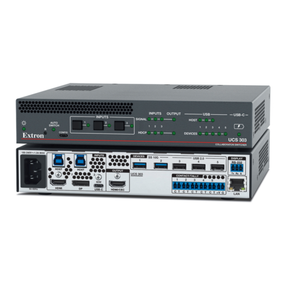
- Page 1 User Guide DVI/HDMI/USB Switchers UCS 303 Three Input, One Output Collaboration Switcher 68‑3538‑01 Rev. A 12 23...
- Page 2 Safety Instructions Safety Instructions • English WARNING: This symbol, , when used on the product, is intended to alert the user of the presence of uninsulated dangerous voltage within the product’s enclosure that may present a risk of electric shock. ATTENTION: This symbol, , when used on the product, is intended...
- Page 3 Copyright © 2023 Extron. All rights reserved. www.extron.com Trademarks All trademarks mentioned in this guide are the properties of their respective owners. The following registered trademarks ( ® ), registered service marks ( ), and trademarks ( ) are the property of RGB Systems, Inc. or Extron (see the current list of trademarks on the page at Terms of Use...
- Page 4 FCC Class A Notice This equipment has been tested and found to comply with the limits for a Class A digital device, pursuant to part 15 of the FCC rules. The Class A limits provide reasonable protection against harmful interference when the equipment is operated in a commercial environment.
- Page 5 Conventions Used in this Guide Notifications The following notifications are used in this guide: Risk of minor personal injury. CAUTION: ATTENTION : Risque de blessure mineure. ATTENTION: • Risk of property damage. • Risque de dommages matériels. NOTE: A note draws attention to important information. Software Commands Commands are written in the fonts shown here: ^AR Merge Scene,,0p1 scene 1,1 ^B 51 ^W^C.0...
-
Page 6: Table Of Contents
SIS Communication and Control ....26 Introduction ..........1 Using Simple Instruction Set (SIS) Commands ... 26 About this Guide ..........1 About the UCS 303 Switcher ....... 1 Host-to-switcher Communications ....26 Switcher-initiated Messages ......26 Features .............. 2 USB System Architecture ........ - Page 7 Mounting ..........63 Tabletop Use ..........63 Rack Mounting ..........63 Extron Warranty ........65 UCS 303 • Contents...
-
Page 8: Introduction
Resolutions up to 4K @ 60 Hz are supported, along with EDID Minder, HDCP 2.3, and configuration via Product Configuration Software (PCS). All models extend signals up to 330 feet (100 meters). The UCS 303 is housed in a 1U high, half rack width, 8.5 inches deep enclosure. -
Page 9: Features
Features • Integrates DisplayPort, HDMI, and audio sources into collaboration systems — The UCS 303 provides centralized switching for a wide range of AV sources. • Switches HDMI video and embedded multi‑channel digital audio. • HDMI, DisplayPort, and USB inputs — Provides one female DisplayPort, one female HDMI type A, one USB-C, and two USB 3.2 B host input connectors. -
Page 10: Usb System Architecture
• Easy setup and commissioning with the Extron PCS program — Conveniently configure multiple products using a single software application. Rack‑mountable metal enclosure — The UCS 303 features a 1U, half rack wide • metal enclosure with integrated rack mounts. - Page 11 NOTE: If the host device runs Windows or macOS™ operating systems, use the ® following programs to view the hierarchical relationships between USB devices: • Windows: Device Manager • macOS: System Profiler or System Information UCS 303 • Introduction...
-
Page 12: Application Diagrams
+ V + S -S G Ethernet PWR OUT = 6W Extron IPCP Pro 250 xi IPCP Pro xi Control Processor Figure 3. Sample Application for UCS 303 — Teams Room with Collaboration PC and Control Panel UCS 303 • Introduction... - Page 13 Tx Rx G UCS 303 CONTACT/TALLY HDMI USB-C HDMI/CEC C T +V G 50-60Hz Camera Extron HDMI POWER STANDBY Ethernet UCS 303 Collaboration Switcher Display HDMI Figure 4. Sample Application for UCS 303 with Audio Amplifier and Processor UCS 303 • Introduction...
-
Page 14: Installation
Installation This section describes the installation and setup of the UCS 303 switcher. Topics include: • Installation Overview • Rear Panel Connections Wiring the CONTACT/TALLY Connectors • • LockIt HDMI Cable Lacing Bracket Installation • Wiring the LAN Port •... -
Page 15: Rear Panel Connections
Auto‑switch mode commands on page 29) (optional). Power on the connected devices. Connect power ( ) to the switcher. ATTENTION: Do not connect power to the UCS 303 until you have read the ATTENTION • notices on page 11. • Ne branchez pas l’alimentation au UCS 303 avant d’avoir lu les mises en garde «... - Page 16 RS‑232 display control port — Connect this port to the RS-232 connector of a display to control the display. The port can be configured using PCS (see the UCS 303 Help File) to control the display in the following modes:...
-
Page 17: Wiring The Contact/Tally Connectors
This port provides up to 60 watts of power to the connected source. If the source requires more than 60 watts, this port keeps the device functioning but does not charge it. If the source is connected to an external power supply, the UCS 303 does not send power to it. - Page 18 Optionally, successive contact closures of the current input can be configured to toggle A/V mute or output sync mute. If None is selected, contact events broadcast unsolicited SIS responses for action via external control system. Tally ports are configured via an external control system. UCS 303 • Installation...
-
Page 19: Connecting Using An Sm Cable
Connecting Using an SM Cable The CONTACT/TALLY connectors can also be used with Extron SM cables. Figure 9 shows how to wire an SM cable to a contact/tally input. Black Cable Figure 9. SM Cable Connecting Contact and Tally Ports UCS 303 • Installation... -
Page 20: Lockit Hdmi Cable Lacing Bracket Installation
• Ne serrez pas trop la vis de montage du connecteur HDMI. Le blindage auquel elle est attachée est très fin et peut facilement être dénudé. UCS 303 • Installation... -
Page 21: Wiring The Lan Port
Ethernet control enables configuration and control of the UCS 303 from a remote location using SIS commands (see Command and Response Table for SIS Commands starting on page 29), PCS (see the UCS 303 Help File), or the embedded web pages (see Internal Web Page starting on page 53). Default LAN settings: Rear panel LAN IP Address —... -
Page 22: Connecting Multiple Ucs 303 Switchers In A System
Connecting Multiple UCS 303 Switchers in a System The USB specification states that a maximum of five hubs (or five UCS 303 switchers) can be connected in a series. Figure 11 shows a single host with a maximum of five UCS 303 switchers cascaded in a series. -
Page 23: Operation
• • HDCP • Color Bit Depth USB‑C Input • • RS‑232 Signal Insertion Front Panel Features Figure 12 shows the front panel LEDs and controls of the UCS 303. INPUTS OUTPUT USB-C INPUTS SIGNAL HOST AUTO SWITCH HDCP DEVICES... - Page 24 NOTE: You can also reset the switcher to its factory default settings using SIS commands (see Resets on page 37) or PCS (see the UCS 303 Help File). Auto Switch LED — Lights when auto-input switching is in effect (see Auto‑switching on page 29).
-
Page 25: Powering On The Switcher
Selection commands on page 29 or the UCS 303 Help File). NOTE: While the UCS 303 is in any auto-switch mode, you can still manually select inputs via front panel buttons or SIS. This allows you to switch to any input during usage and not rely on auto switching. -
Page 26: Auto-Switch Modes
Auto-switch Modes The UCS 303 switchers provide three auto switch modes, which can be selected via SIS commands (see the Auto‑switching commands on page 29) and PCS (see the UCS 303 PCS Help File). Mode 0 (disabled mode) — Auto-input switching is disabled. Inputs must be selected •... -
Page 27: Front Panel Lock Mode (Executive Mode)
EDIDs can be set to match the output rate or a factory setting. A variety of EDIDs are available to be loaded via PCS and assigned to the inputs (see the UCS 303 PCS Help File to assign EDID). -
Page 28: Hdcp
When a Macbook, or any of the other devices listed above, is connected, the output video is unencrypted. • When a source playing content that requires video encryption (for example, Blu-ray) is connected, the source does not output video. UCS 303 • Operation... -
Page 29: Hdcp Encryption
SIS commands: • Automatic — By monitoring the EDID of the sink, the UCS 303 switcher determines the best color depth that is supported by the sink. If the color bit depth of the signal is supported, the signal passes unaltered. -
Page 30: Usb-C Power Delivery
45 watts of power, it is able to keep the source active, but cannot charge it. If the source is already connected to an external power supply, the UCS 303 does not send power to the source. - Page 31 Extron controller provides control of a display via the UCS 303. Configure this type of insertion as follows: Connect a cable from the control system to the LAN port of the UCS 303, directly or via a network. If necessary to match the device to be controlled, configure the port RS-232 protocol (baud rate, parity, data bits, and stop bits) using PCS (see the UCS 303 Help File).
- Page 32 Captive Screw Signal Insertion Figure 14 shows an example of a typical captive screw Ethernet insertion, in which a computer running PCS provides control of a display via the UCS 303. Configure this type of insertion as follows: MODEL 80...
-
Page 33: Sis Communication And Control
Responses from the UCS 303 to the host computer end with a carriage return and a line feed (CR/LF = ]), which signals the end of the response character string. A string is one or more characters. -
Page 34: Error Responses
The conversion table below is for use with the command and response table. ASCII to Hex Conversion Table Space • Figure 15. ASCII to Hex Conversion Table UCS 303 • SIS Communication and Control... -
Page 35: Unsolicited Responses
E or W = Escape NOTE: Commands are not case-sensitive. Command For symbol definitions for specific commands, see the command listing in the and Response Table for SIS Commands starting on the next page. UCS 303 • SIS Communication and Control... -
Page 36: Command And Response Table For Sis Commands
0 = Off or disabled (default) = Auto-switch mode 1 = User-defined priority 2 = Input memory priority X1& 1 = Input 1, 2 = input 2, 3 = input 3 = Auto-switch priority UCS 303 • SIS Communication and Control... - Page 37 3 = HDMI RGB 444 Full 4 = HDMI RGB 444 Limited 5 = HDMI YUV 444 Limited 6 = HDMI YUV 422 Limited 0-500 seconds in 1-second intervals. Default is 3 seconds. = Auto-switch timeout (mode 2) UCS 303 • SIS Communication and Control...
- Page 38 = Slot number on EDID lookup table X& = 128 or 256 byte EDID raw HEX (text form) from currently assigned EDID Example: 1920x1080 @ 60 Hz. = Native resolution and refresh rate from currently assigned EDID UCS 303 • SIS Communication and Control...
- Page 39 View subnet mask KEY: 0 = Off or disabled (default), 1 = On or enabled = DHCP mode setting Format nnn.nnn.nnn.nnn (Default is 192.168.254.254) = IP address Format nnn.nnn.nnn.nnn (Default is 255.255.255.0) = Subnet mask UCS 303 • SIS Communication and Control...
- Page 40 View format: Day of week, day•month•year•hour:minutes:seconds (Www,DD•Mmm•YYYY•HH:MM:SS) Example: Fri, 21 Jun 2002 10:54:00 X3& 1-3 (If the NIC number is not applicable to the UCS 303, an E13 error Network interface card (NIC) number message is returned.) UCS 303 • SIS Communication and Control...
- Page 41 Model name followed by the last three character pairs of the MAC = Default unit name address. Example: UCS-303-00-02-3D 0 = Off or disabled (default), 1 = Front panel lockout = Front panel lock (executive) mode UCS 303 • SIS Communication and Control...
- Page 42 View the SIS-over-SSH port X3& View the current SIS-over-SSH PMAP {port number} mapping port mapping. KEY: 0 = Off or disabled, 1 = On or enabled (default) Echo status X3& Network interface card (NIC) number UCS 303 • SIS Communication and Control...
- Page 43 View status of all tally ports X2(] TALY •... View status of all tally ports. KEY: 1 through 5 = Contact/Tally port number 0 = Open, 1 = Closed = Contact/Tally port state UCS 303 • SIS Communication and Control...
- Page 44 Indicator Model Cmd. number version and time description 0Q1.00-1.00.0000-b115(2.07LX-SW USB PRO -Fri, 16 Jul 2023 15.42 UTC)-1.00.0000-b004*(2.07LX-UCS 303 -Tue, 03 Aug 2023 17:56 UTC)] Boot Factory base firmware version Updated firmware version loader version KEY: Number of the currently selected input.
- Page 45 NOTE: Entering this command or performing an absolute system reset via the front panel Reset button (see Resetting page 19) changes the current passwords (whether user-set or the factory-set serial number) to extron. UCS 303 • SIS Communication and Control...
-
Page 46: Symbol Definitions For Cec Communications Commands
(Example: %2A%07%FF) = CEC address byte: In the form of percent sign followed by two hex digits Example: %E0 = Extron output (14) to TV (0) NOTE: Unless otherwise indicated, commands are not case-sensitive. UCS 303 • SIS Communication and Control... -
Page 47: Command And Response Table For Cec Communications Sis Commands
) in the form of percent sign followed by two hex digits (Example: %2A%07%FF) = CEC address byte In the form of percent sign followed by 2 hex digits Example: %E0 = Extron output (14) to TV (0) UCS 303 • SIS Communication and Control... - Page 48 = CEC physical address 4 hexadecimal digits in the form of = CEC address byte In the form of percent sign followed by 2 hex digits Example: %E0 = Extron output (14) to TV (0) UCS 303 • SIS Communication and Control...
-
Page 49: Product Configuration Software
Software The Extron Product Configuration Software (PCS) offers another way to configure the UCS 303 Collaboration switchers via a USB-C connector in addition to the SIS commands. This section describes software installation and communication, along with updating firmware. Topics in this section include: •... - Page 50 NOTE: If you are installing a PCS version that is 4.8.n or higher, you are required to enter an Extron Insider ID number again. See your Extron representative if you require assistance. UCS 303 • Product Configuration Software...
-
Page 51: Starting Pcs
Double-click on the EAF.exe file, located on your computer at • c:\Program Files(x86)]\Extron\Extron PCS. In the Device Discovery panel of the PCS window, click on the name of your UCS 303 (see figure 18, ). (You may need to scroll to locate it, depending on the number of devices listed.) The Connect button (... - Page 52 PCS screen. When finished viewing the tutorial, click OK to close the screen. The Extron PCS device configuration window opens. Figure 20. UCS 303 Device Configuration Window UCS 303 • Product Configuration Software...
-
Page 53: Connecting Using The Tcp/Ip Panel
(the default is 4523). NOTE: If the TCP/IP port number is not known, leave this field blank. PCS scans for the port and fills it in. Click the Connect button ( ). A new device tab opens. UCS 303 • Product Configuration Software... -
Page 54: Updating Firmware
Device panel (see figure 21, Target the previous page), enter the IP address of the UCS 303 on the AV LAN, as well as the port number (the default is 4523) and the password. Select the Enable Indirect Connection checkbox (... - Page 55 Figure 22. Software Link on the Download Page Click the Software link ( ) in the Downloads column. On the Download Center page, click the F link (see figure 23, ) on the next page). UCS 303 • Product Configuration Software...
- Page 56 Click the installer icon and follow the instructions on the subsequent screens to install Firmware Loader on your PC. NOTE: When downloaded from the Extron website, by default the Firmware Loader files are placed at C:\Program Files (x86)\Extron\FWLoader. UCS 303 • Product Configuration Software...
-
Page 57: Updating Firmware Using Firmware Loader
) at the bottom of the dialog box. The Add Device window closes, and Click Add ( the UCS 303 information is added to the Device panel of the Firmware Loader dialog box. Double click on <double click to set> in the New Firmware File column. - Page 58 The Total Progress panel ( ) displays a progress bar with Uploading above it. • In the Devices panel ( ), the Progress column displays an incrementing • percentage and another progress bar. The Status column displays Uploading. UCS 303 • Product Configuration Software...
- Page 59 Status column. Close the Firmware Loader dialog box. NOTE: The original factory-installed firmware is permanently available on the UCS 303. If the attempted firmware upload fails for any reason, the switcher reverts to the factory version. UCS 303 • Product Configuration Software...
-
Page 60: Internal Web Page
Internal Web Page The embedded UCS 303 web page enables you to monitor and adjust certain settings of the UCS through its Ethernet port, connected via a LAN, WAN, or IP over USB, and using a web browser such as Microsoft... -
Page 61: Web Page Components
Internal Web Page Details Panel This view-only panel contains the following information about the unit (see figure 28, • The unit name (Hostname) Product description (Multi Graphic Processor) • • Part number (60-1797-01) • Unit serial number UCS 303 • Internal Web Page... -
Page 62: Status Panel
NOTE: The Set Date & Time field must be set to Manual. If it is set to Sync to NTP Servers, the SYNC to PC button is unavailable. Click EDIT, then select the Manual radio button and click SAVE (see Syncing to NTP servers on page 57). UCS 303 • Internal Web Page... - Page 63 Datepicker (see figure 31, ) or the Timepicker ( ) icon to display the following panels: Figure 31. Datepicker and Timepicker Screens UCS 303 • Internal Web Page...
- Page 64 ) to confirm them, or CANCEL to close the SAVE dialog box without implementing the settings. Syncing to NTP servers To set the date, time, and time zone by syncing the UCS 303 with a network server: Figure 32. Syncing the UCS 303 to Network Servers Select the radio button.
-
Page 65: Network Panel
In the Network panel you can set the hostname, IP address, subnet mask, and gateway address for your UCS 303, and turn DHCP on and off. You can also view the MAC address of the unit. To set the IP addresses: Click the down arrow at the right of the field to view the network settings. -
Page 66: Passwords Panel
). (You may need to click this button again to make it CREATE available.) The UCS 303 web page closes and the login page is displayed. Enter the username (the default is ) and the new password to access the UCS 303 Admin web page. -
Page 67: Firmware Panel
You can update the firmware on your UCS from this panel (firmware files can be downloaded from www.extron.com). To update firmware: In the Firmware panel, click the button (see figure 36, Select File Figure 36. SELECT FILE Button on the Firmware Panel UCS 303 • Internal Web Page... - Page 68 In the Open dialog box, browse to locate the new firmware file on your computer (by default the file is stored at C:\Program Files (x86)\Extron\Firmware). Figure 37. Open Window for UCS 303 Firmware ATTENTION: Valid firmware files must have an .eff file extension. A file with any other •...
- Page 69 When the update is complete, the unit restarts, and the login web page is displayed. After you log in, the new firmware filename appears under Current Version in the Firmware panel of the web page. UCS 303 • Internal Web Page...
- Page 70 Rack Mounting The UCS 303 switcher can be mounted on a full- or half-rack shelf, or through or under furniture. Mounting kits are available at www.extron.com. For mounting procedures, see the instructions provided with the mounting option.
- Page 71 Consignes UL pour le Montage en Rack Les consignes UL (« Underwriters Laboratories ») suivantes concernent l’installation en rack d’un boîtier UCS 303 : ATTENTION : • Température ambiante élevée — En cas d’installation de l’équipement dans un rack fermé ou composé de plusieurs unités, la température du rack peut être supérieure à...
- Page 72 Extron Electronics makes no further warranties either expressed or implied with respect to the product and its quality, performance, merchantability, or fitness for any particular use. In no event will Extron Electronics be liable for direct, indirect, or consequential damages resulting from any defect in this product even if Extron Electronics has been advised of such damage.
Need help?
Do you have a question about the UCS 303 and is the answer not in the manual?
Questions and answers