Extron electronics XTP T USW 103 User Manual
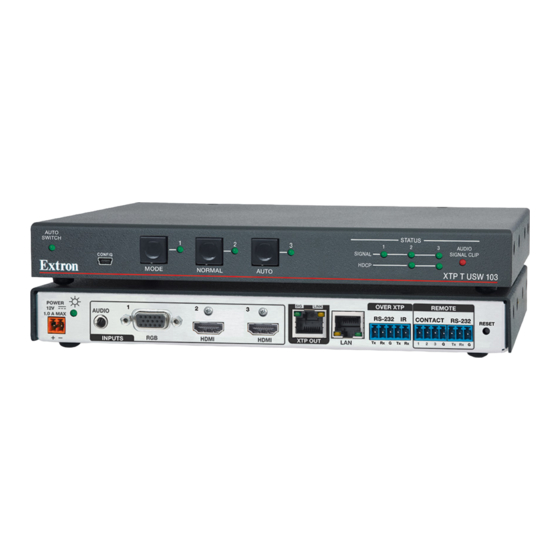
Three input switcher
with an integrated xtp transmitte
Hide thumbs
Also See for XTP T USW 103:
- User manual (47 pages) ,
- User manual (37 pages) ,
- User manual (47 pages)
Table of Contents
Advertisement
Quick Links
Download this manual
See also:
User Manual
Advertisement
Table of Contents

Subscribe to Our Youtube Channel
Related Manuals for Extron electronics XTP T USW 103


Summary of Contents for Extron electronics XTP T USW 103
- Page 1 User Guide XTP Switcher XTP T USW 103 Three Input Switcher with an Integrated XTP Transmitter 68-2292-01 Rev. D 04 14...
-
Page 2: Safety Instructions
Safety Instructions Safety Instructions • English Инструкция по технике безопасности • Русский WARNING: This symbol, , when used on the product, is intended to ПРЕДУПРЕЖДЕНИЕ: Данный символ, , если указан alert the user of the presence of uninsulated dangerous voltage within the на... - Page 3 Compliance Guide” on the Extron website. Copyright © 2014 Extron Electronics. All rights reserved. Trademarks All trademarks mentioned in this guide are the properties of their respective owners. The following registered trademarks , registered service marks...
-
Page 4: Conventions Used In This Guide
Conventions Used in this Guide Notifications The following notifications are used in this guide: A warning indicates a situation that has the potential to result in death or WARNING: severe injury. ATTENTION: Attention indicates a situation that may damage or destroy the product or associated equipment. -
Page 5: Table Of Contents
........... 1 Commands ............. 15 About this Guide ..........1 Input Commands .......... 15 About the XTP T USW 103 ......... 1 Audio Configuration Commands ....15 Key Features ............2 Picture Adjustment Commands (Analog Only) 16 Preset Commands ........16 Installation ............. - Page 6 XTP T USW 103 Switcher • Contents...
-
Page 7: Introduction
XTP matrix switcher (see Power Connection on page 8). To configure and control the XTP T USW 103, connect it to a host device, such as a computer, and enter Simple Instruction Set (SIS) commands (see SIS Configuration and... -
Page 8: Key Features
Ethernet pass-through port to reduce the amount of independent network drops required within a system. Remote power capability — To simplify integration, the XTP T USW 103 can be powered by an XTP CrossPoint Matrix Switcher or XTP Power Injectors. -
Page 9: Installation
Rear Panel Connectors Audio Plugs.eps • Making Connections The XTP T USW 103 can be mounted in a rack, under a desk, or on a tabletop (see Mounting on page 32 for more mounting details). Tip (+) Rear Panel Connectors... - Page 10 LAN connector — Connect a control device or device to be controlled to this LAN connector for 10/100 Ethernet communication through this pass-through port. LEDs on this connector indicate link and activity status. XTP T USW 103 Switcher • Installation...
-
Page 11: Making Connections
2-pole captive screw connector (see Power Connection on page 8). The Power LED lights to indicate the device is receiving power. NOTE: The XTP T USW 103 can be powered remotely (see Remote power page 9). Making Connections HDMI Connection Use an Extron LockIt Lacing Bracket to secure an HDMI cable to top mounting screw of an HDMI connector. -
Page 12: Tp Cable Termination And Recommendations
Connector Figure 5. TP Cable Termination Supported cables The XTP T USW 103 is compatible with shielded twisted pair (F/UTP, SF/UTP, and S/FTP) and unshielded twisted pair (U/UTP) cables. ATTENTION: • Do not use Extron UTP23SF-4 Enhanced Skew-Free AV UTP cable or STP201 cable to link the XTP products. -
Page 13: Contact Closure Communication
The length of exposed wires is critical. ATTENTION: • The ideal length is 3/16 inch (5 mm). • Longer bare wires can short together. • Shorter wires are not as secure in the connectors and could be pulled out. XTP T USW 103 Switcher • Installation... -
Page 14: Power Connection
Output Cord Figure 8. Power Wiring The XTP T USW 103 can be connected to a local power supply. Electric shock hazard. The two power cord wires must be kept separate WARNING: while the power supply is plugged in. Remove power before wiring. -
Page 15: Remote Power
Remote power The XTP T USW 103 can be powered remotely through an XTP Power Injector or through an XTP matrix switcher. ATTENTION: XTP remote power is intended for indoor use only. No part of the network that uses XTP remote power should be routed outdoors. -
Page 16: Operation
Operation This section describes the front panel features and operations of the XTP T USW 103. Topics in this section include: • Front Panel Features • Front Panel Operation Front Panel Features AUTO STATUS SWITCH AUDIO SIGNAL CLIP SIGNAL CONFIG... -
Page 17: Selecting An Input
(see EDID Minder on page 30). The XTP T USW 103 can record and save EDID in a user memory location, select a pre-defined EDID, or use EDID from a display connected to a receiver. EDID stored in the user memory location can come from the display connected to a receiver or a custom EDID imported through the XTP System Configuration Software. -
Page 18: Reset Mode
1 reset by mistake, NOT operate the system cycle power to the device to with the firmware version that return the firmware version results from this mode reset. running prior to the reset. XTP T USW 103 Switcher • Operation... -
Page 19: Sis Configuration And Control
To connect directly to an XTP T USW 103, connect the computer to the XTP T USW 103 through the front panel USB Config port or the rear panel RS-232 connector. The protocol for the serial port is as follows: 9600 baud, no parity, 8 data bits, 1 stop bit, no flow control. -
Page 20: Error Responses
Error Responses When the XTP T USW 103 receives an SIS command and determines that it is valid, it performs the command and sends the corresponding response to the host device. If the command is determined invalid or contains invalid parameters, the switcher returns an error response to the host. -
Page 21: Command And Response Tables For Sis Commands
= priority to the highest numbered active input = priority to the lowest numbered active input = Black signal resolution = 720p @ 50 Hz = 720p @ 60 Hz = 1080p @ 60 Hz XTP T USW 103 Switcher • SIS Configuration and Control... -
Page 22: Picture Adjustment Commands (Analog Only)
Recall the preset configuration. = Enable or disable = disable NOTE: = enable = Pixel phase = default) 0-255 = Horizontal or vertical shift = default) 65535 32768 = Preset number XTP T USW 103 Switcher • SIS Configuration and Control... -
Page 23: Edid Commands
= HDMI (input 3) = Enable or disable = disable or unlock (default for executive mode) = enable or lock = HDCP Authorization = HDCP authorization off = HDCP authorization on (default) XTP T USW 103 Switcher • SIS Configuration and Control... - Page 24 = HDCP status = no source connected = HDCP compliant source = non-HDCP compliant source = Video signal status = video or TMDS not detected = video or TMDS detected XTP T USW 103 Switcher • SIS Configuration and Control...
-
Page 25: Xtp System Configuration Software
13) or the XTP System Configuration Software. This section contains installation and configuration procedures for the XTP System Configuration Software for configuring and controlling the XTP T USW 103. Topics in this section include: Installing the XTP System Configuration Software •... -
Page 26: Using The Xtp System Configuration Software
Using the XTP System Configuration Software The XTP T USW 103 can be controlled directly from the front panel config port or remotely from an XTP matrix switcher. Connections When opening the XTP System Configuration Software, the Connections screen opens first. -
Page 27: Top Menu
To access this menu, click the Tools menu. Tools Figure 16. Tools Menu NOTE: The options are not Backup and Restore Software Preference available when directly connected to the XTP T USW 103. XTP T USW 103 Switcher • XTP System Configuration Software... -
Page 28: Update Firmware
Select file from computer connected host device. Select the desired firmware file and click the button. Open Click the button after the firmware finishes updating. Close XTP T USW 103 Switcher • XTP System Configuration Software... - Page 29 This option opens the XTP System Configuration Software help file in a Web browser. From the menu, select Help Help Extron Website This option opens the Extron website in a Web browser. From the menu, select Help Extron Website XTP T USW 103 Switcher • XTP System Configuration Software...
-
Page 30: Device Settings
NOTE: The signal indicators on the AV input buttons display green when a signal is present on the corresponding input or gray when there is no signal present. XTP T USW 103 Switcher • XTP System Configuration Software... - Page 31 Auto-Image is applied whenever there is a change in the input sync. Auto Memory — Recalls input and image settings for signals that have previously been applied. When it is disabled, the XTP T USW 103 treats every newly applied input as a new source.
- Page 32 Save Preset — To save a preset, select one from the list of presets and click the Save button. Preset Recall Preset — To recall a saved preset, select the desired preset from the list of presets and click the button. Recall Preset XTP T USW 103 Switcher • XTP System Configuration Software...
- Page 33 Analog Audio Gain — Click and drag the handle of the slider, enter a value in the Gain field, or click the arrow to adjust the analog input gain. Down XTP T USW 103 Switcher • XTP System Configuration Software...
-
Page 34: General Tab
Factory Reset firmware. NOTE: This is the same as the SIS command (see the System reset ZXXX command on page 18). XTP T USW 103 Switcher • XTP System Configuration Software... - Page 35 HDCP — Displays the HDCP status of inputs 2 and 3. Audio Information section Selected Audio Input — Displays the type of the currently selected audio input. Analog Audio Gain — Displays the analog audio gain in dB. XTP T USW 103 Switcher • XTP System Configuration Software...
-
Page 36: Edid Minder
Favorites, Connected Outputs, or Available EDID panel (see Below the list of inputs on the right side of the screen, click the button Assign to All (see XTP T USW 103 Switcher • XTP System Configuration Software... - Page 37 ). The tab appears, listing the EDID settings common Common Timings among the selected outputs. Select the desired common EDID setting. The EDID is shown in the Available EDID panel. XTP T USW 103 Switcher • XTP System Configuration Software...
-
Page 38: Reference Information
• Updating Firmware with Firmware Loader Mounting The XTP T USW 103 can be placed on a tabletop, mounted in a rack, or mounted underneath a desk. Tabletop Placement Attach the provided rubber feet to the bottom four corners of the enclosure. -
Page 39: Updating Firmware With Firmware Loader
Updating Firmware with Firmware Loader To upload and update firmware for the XTP T USW 103, download the new firmware to a connected computer and upload the firmware to the XTP T USW 103 with the Firmware Loader utility. Downloading Extron Firmware Loader Figure 28. -
Page 40: Installing Firmware Loader
Click the link to the right of the desired device. Download If required, enter any required information to start the download. Note where the file is saved. XTP T USW 103 Switcher • Reference Information... -
Page 41: Installing Firmware With Firmware Loader
Click the button to start the upload process. Begin Close Firmware Loader when the field shows , the Remaining Time 00.00.00 column shows , and the field shows Progress 100% Status completed XTP T USW 103 Switcher • Reference Information... -
Page 42: Extron Warranty
Extron Electronics makes no further warranties either expressed or implied with respect to the product and its quality, performance, merchantability, or fitness for any particular use. In no event will Extron Electronics be liable for direct, indirect, or consequential damages resulting from any defect in this product even if Extron Electronics has been advised of such damage.
Need help?
Do you have a question about the XTP T USW 103 and is the answer not in the manual?
Questions and answers