Extron electronics DTP T USW 233 User Manual
Three input switcher with integrated dtp transmitter
Hide thumbs
Also See for DTP T USW 233:
- Setup manual (4 pages) ,
- Setup manual (4 pages) ,
- User manual (42 pages)

Related Manuals for Extron electronics DTP T USW 233


Summary of Contents for Extron electronics DTP T USW 233
- Page 1 DTP T USW 233 Three Input Switcher with Integrated DTP Transmitter User Guide DTP Systems 68-2490-01, Rev. G 02 24...
- Page 2 Safety Instructions Safety Instructions • English WARNING: This symbol, , when used on the product, is intended to alert the user of the presence of uninsulated dangerous voltage within the product’s enclosure that may present a risk of electric shock. ATTENTION: This symbol, , when used on the product, is intended to alert the user of important operating and maintenance (servicing)
- Page 3 Copyright © 2013-2024 Extron. All rights reserved. www.extron.com Trademarks All trademarks mentioned in this guide are the properties of their respective owners. The following registered trademarks ( ® ), registered service marks ( ), and trademarks ( ) are the property of RGB Systems, Inc. or Extron (see the current list of trademarks on the page at Terms of Use...
- Page 4 FCC Class A Notice This equipment has been tested and found to comply with the limits for a Class A digital device, pursuant to part 15 of the FCC rules. The Class A limits provide reasonable protection against harmful interference when the equipment is operated in a commercial environment.
- Page 5 Conventions Used in this Guide Notifications The following notifications are used in this guide: CAUTION: Risk of minor personal injury. ATTENTION : Risque de blessure mineure. ATTENTION: • Risk of property damage. • Risque de dommages matériels. NOTE: A note draws attention to important information. TIP: A tip provides a suggestion to make working with the application easier.
-
Page 7: Table Of Contents
Introduction ..............1 Reference Information ..........27 About this Guide ............. 1 Mounting the Switcher .......... 27 About the DTP T USW 233 Switcher ...... 1 Tabletop Use ............. 27 STP Cable ............2 Mounting kits ............. 27 Control Communications ........2 UL Rack-Mounting Guidelines...... - Page 8 DTP T USW 233 • Contents viii...
-
Page 9: Introduction
Figure 1. Typical Switching Transmitter Application The DTP T USW 233 is housed in a half rack width metal enclosure. It can be set on a tabletop, mounted in a rack, or mounted under or through furniture. The included external desktop 12 VDC power supply accepts 100 to 240 VAC, 50-60 Hz. A single power supply connected to either unit can power both units through the STP cable. -
Page 10: Stp Cable
Supports computer video to 1920x1200, including HDTV 1080p/60 Deep Color and 2K — The DTP T USW 233 supports digital signal transmission up to 230 feet over a single twisted pair cable and maintains superior image quality at the highest resolutions. - Page 11 HDCP compliance for quick, reliable switching in professional AV environments. • Compatible with all DTP 230 receivers, and DTP 230-enabled products — Enables mixing and matching with desktop and wallplate receivers, as well as other DTP 230-enabled products to meet application requirements. DTP T USW 233 • Introduction...
-
Page 12: Installation And Operation
Installation and Operation This section describes the installation and the operation of the DTP T USW 233, including: • Mounting the Unit • Connections and Reset Button • Operation • Troubleshooting — If No Image Appears Mounting the Unit Mounting instructions can be found in Mounting the Switcher on page 27. -
Page 13: Connections And Reset Button
If the ground jumpers have been removed (see Disconnecting the Ground on page 29) because of ground potential differences, the DTP T USW 233 cannot extend analog audio. The connected receiver outputs no analog audio. • The analog audio can be assigned to a specific input or set to be always output (see SIS command Assign analog audio input to specific video input or always output audio on page 17). - Page 14 If you have removed the ground jumpers (see on page 29) because of ground potential differences, one unit of the pair cannot remotely power the other unit. Each unit requires a local power supply. DTP T USW 233 • Installation and Operation...
-
Page 15: Connector And Cable Details
4. Loosely place the included tie wrap around the HDMI connector and the LockIt lacing bracket as shown ( 5. While holding the connector securely against the lacing bracket, use pliers or similar tools to tighten the tie wrap, then remove any excess length ( DTP T USW 233 • Installation and Operation... - Page 16 Figure 5. STP Cable Termination Supported cables The DTP T USW 233 is compatible with shielded twisted pair (STP) and unshielded twisted pair (U/UTP) cable. However, Extron strongly recommends that you use STP cable to achieve best performance. Cable recommendations Extron recommends using the following practices to achieve full transmission distances up to 230 feet (70 meters) and reduce transmission errors.
- Page 17 • Ne pas étamer les conducteurs avant de les insérer dans le connecteur. Les câbles étamés ne sont pas aussi bien fixés dans le connecteur et pourraient être retirés. DTP T USW 233 • Installation and Operation...
- Page 18 The IR Tx and Rx line pair and the RS-232 Tx and Rx line pairs must each cross once between their connectors and the source or destination. • The length and preparation of exposed wires is important (see the second and third power connector CAUTION on page 9 for details). DTP T USW 233 • Installation and Operation...
-
Page 19: Front Panel Configuration Port
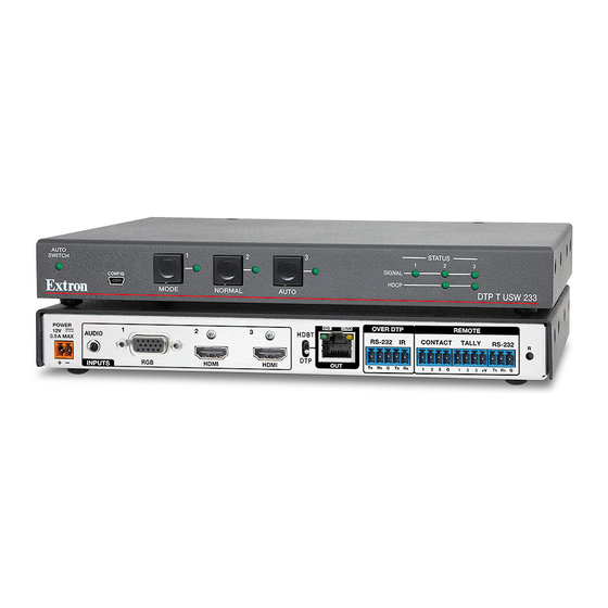
CONFIG HDCP AUTO MODE NORMAL DTP T USW 233 Figure 9. DTP T USW 233 Front Panel Controls and Indicators Auto Switch LED Mode buttonn Auto(switch) button Input 1 through 3 buttons Normal button Status LEDs Input 1 through 3 LEDs Auto Switch mode indicator Auto Switch LED —... -
Page 20: Front Panel Operations
NOTE: The switcher must be in normal (manual) mode. An input can also be selected using an RS-232 or USB device or a contact closure device (see Remote Control starting on page 14). DTP T USW 233 • Installation and Operation... -
Page 21: Troubleshooting - If No Image Appears
3. Ensure that the proper signal format is supplied. 4. Check the cabling and make corrections as necessary. 5. Call the Extron S3 Sales & Technical Support Hotline if necessary. See the Extron website for the Extron office nearest you. DTP T USW 233 • Installation and Operation... -
Page 22: Remote Control
Simple Instruction Set Control • Product Configuration Software The DTP T USW 233 switcher can be remotely controlled via its rear panel Remote RS-232 port and front panel configuration (USB) port. Remote control devices can be: • A host device such as a computer or control system and the Extron Simple Instruction Set •... -
Page 23: Error Responses
= Auto-input switching low = Auto-input switching high NOTE: Auto-input switch low ( ) is not available from the front panel. X# = Status = Off, disabled, or not detected = On, enable, or detected DTP T USW 233 • Remote Control... - Page 24 X1^ = Firmware version number to second decimal place ( x.xx ) X1& = Clear/none = Verbose mode (default) Verbose mode = Tagged responses for queries = Verbose mode and tagged for queries DTP T USW 233 • Remote Control...
-
Page 25: Command And Response Table For Sis Commands
= Input HDCP status = No source detected = Source detected with HDCP = Source detected without HDCP = Output HDCP status = No sink detected = Sink detected with HDCP = Sink detected without HDCP DTP T USW 233 • Remote Control... - Page 26 Via contact closure. MUTM KEY: X# = Status = Off or disabled = On or enable = Configure tally pin when enabled = Always on (default) = Off when muted = Blink when muted DTP T USW 233 • Remote Control...
- Page 27 See the table with on page 20. EDID Values = User EDID location , or = Raw EDID data bytes of hexadecimal data 1920x1200 @60.00Hz = Resolution and rate in plain text Example: • DTP T USW 233 • Remote Control...
-
Page 28: Edid Values
1080p @ 60 Hz Output and user locations Source Source Source Source Output User location 1 User location 2 User location 3 Default for input 1. ^ Default for inputs 2 and 3. DTP T USW 233 • Remote Control... -
Page 29: Product Configuration Software
5. Click the appropriate letter to locate the software or firmware. The requested alphabetical page opens. 6. Navigate to the desired software and click Download (see figure 15, ). Follow the on-screen instructions. Figure 15. PCS Software Download DTP T USW 233 • Remote Control... - Page 30 Figure 16. Firmware Page with Alphabetic Navigation Bar a. Click the letter D from the alphabetic navigation bar (see figure 16, b. Scroll down the page to find the firmware for the DTP T USW 233. c. (Optional) Click Release Notes ( ) for more information about the firmware update.
-
Page 31: Connecting To Pcs
2 2 2 2 Figure 17. Device Discovery Screen 2. Select the DTP T USW 233 unit by clicking on it to highlight it in the list ( 3. Click Connect ( ). The Product Configuration Software opens to the Input/Output Configuration window (see figure 18). - Page 32 ). The dialog box closes and the reset is complete. Alternatively, click the Close button ( ) to close the dialog box without re-enabling the confirmation dialog. Figure 22. Software Settings Dialog Box DTP T USW 233 • Remote Control...
- Page 33 2. Click the Details button (see figure 24, ) for more information. 3. To display details about third-party software packages and associated licensing, click Licenses ( 4. Click the OK button ( ) to close the dialog box. DTP T USW 233 • Remote Control...
-
Page 34: Updating The Firmware
1. Download the current firmware to a PC connected to the DTP T USW 233 from the Extron website (see Installing the Software/Firmware on page 21). 2. Open PCS and connect to the DTP T USW 233 device (see Device Discovery Panel on page 23). -
Page 35: Reference Information
(voir Disconnecting the Ground). The 1-inch high, half rack width DTP T USW 233 switching transmitter can be placed on a table, mounted in a rack, or mounted under a desk or table. Tabletop Use Affix the included rubber feet to the bottom of the unit and place it in any convenient location. -
Page 36: Ul Rack-Mounting Guidelines
UL Rack-Mounting Guidelines The following Underwriters Laboratories (UL) requirements pertain to the installation of the DTP T USW 233 into a rack. CAUTION: • Elevated operating ambient temperature — If installed in a closed or multi-unit rack assembly, the operating ambient temperature of the rack environment may be greater than room ambient. Therefore, consider installing the equipment in an environment compatible with the maximum ambient temperature (TMA = +122°F, +50°C) specified by Extron. -
Page 37: Disconnecting The Ground
(as suggested by a missing or unstable picture), remove the ground connection between the units as follows: NOTE: Once the ground jumpers are removed, the DTP T USW 233 cannot extend analog audio and one unit cannot remotely power the other. No analog audio is output and the paired receiver requires its own dedicated power supply. - Page 38 « Classe 2 » ou « LPS » et normée 12 Vcc, 1,0 A minimum. Utilisez toujours une source d’alimentation fournie ou recommandée par Extron. L’utilisation d’une source d’alimentation non autorisée annule toute conformité réglementaire et peut endommager la source d’alimentation ainsi que le produit final. DTP T USW 233 • Reference Information...
- Page 39 Extron Electronics makes no further warranties either expressed or implied with respect to the product and its quality, performance, merchantability, or fitness for any particular use. In no event will Extron Electronics be liable for direct, indirect, or consequential damages resulting from any defect in this product even if Extron Electronics has been advised of such damage.
Need help?
Do you have a question about the DTP T USW 233 and is the answer not in the manual?
Questions and answers