Simplex 4010ES Operator's Manual
Hide thumbs
Also See for 4010ES:
- Installation manual (110 pages) ,
- Operator's manual (40 pages) ,
- Installation instructions manual (26 pages)
Table of Contents
Advertisement
Advertisement
Table of Contents

Related Manuals for Simplex 4010ES


Summary of Contents for Simplex 4010ES
- Page 1 4010ES Fire Alarm Operator’s Manual 579-969 Rev. C...
- Page 2 © 2011-2016 Tyco Fire Protection Products. All rights reserved. All specifications and other Copyright information shown were current as of document revision date and are subject to change without notice. TYCO, SIMPLEX, and the product names listed in this material are marks and/or registered marks. Unauthorized use is strictly prohibited.
-
Page 3: Table Of Contents
Acknowledging an Alarm ..........2-2 How the 4010ES Indicates that an Alarm has Occurred ............2-2 Overview - Acknowledging Alarms .................. - Page 4 Overview ............. . . 4-2 How the 4010ES Indicates the Presence of a Supervisory Condition ........4-2 What Acknowledge Does ......................
- Page 5 Overview..........................6-5 Procedure ..........................6-5 Enabling and Disabling Points ..........6-6 Overview..........................
-
Page 7: Ch. 1. Basic Concepts And Operations
Chapter 1 Basic Concepts and Operations Introduction This chapter provides an overview of the 4010ES operator interface panel and describes the normal appearance of the operator interface panel. In this Chapter Refer to the page number listed in this table for information on a specific topic. -
Page 8: Basic System Description
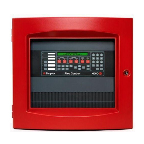
Some devices may take up multiple points in a system. The 4010ES operator interface, shown in Figure 1-1, allows a system operator to control and monitor the facility-specific components connected to the 4010ES FACP. - Page 9 Basic System Description, Continued Overview Table 1-1. Components of the Operator Interface (continued) LED/Key Description Refer To The WARNINGS LEDs – SUPERVISORY and TROUBLE – Chapter 3 for indicate when abnormal, non-fire Troubles. WARNING LED Keys conditions occur to the fire alarm’s and LEDs wiring or devices.
-
Page 10: Normal Appearance Of Operator Interface Panel
Normal Appearance of Operator Interface Panel Description The 4010ES operator interface panel shows the following under normal conditions. • Green power LED is ON - indicating the panel is receiving AC Power • All other LEDs off. • Alphanumeric display reports that the system is normal, as shown below. -
Page 11: Ch. 2. Alarm Conditions
An alarm condition occurs when an initiating device (such as a manual pull station, smoke detector, etc.) activates. The 4010ES indicates the presence of the alarm condition through messages it displays on the alphanumeric display, by flashing the ALARM indicator, and by activating the building’s notification appliances (horns and strobes). -
Page 12: Acknowledging An Alarm
Acknowledging an Alarm How the 4010ES When an alarm condition is detected by the 4010ES, the panel does the following to indicate the Indicates that an presence of the alarm. Alarm has • Red LED, labeled Fire Alarm flashes. Occurred •... -
Page 13: Globally Acknowledging Alarms
Acknowledging an Alarm, Continued Globally Use the following procedure if the Global Acknowledge option is enabled on your 4010ES system. Acknowledging Unlock and open the enclosure door. Read the alphanumeric display on the interface panel. It Alarms reports the number of alarm conditions as shown below. - Page 14 Acknowledging an Alarm, Continued Individually Press the FIRE ALARM ACK key again. Read the report data. Repeat this procedure to review Acknowledging all reports. Reports are displayed in chronological order. Alarms • Tone-alert silences when the last unacknowledged alarm is acknowledged. •...
-
Page 15: Silencing An Alarm
Silencing an Alarm Overview When an alarm condition exists, various signals (horns and strobes), auxiliary relays, the city connection (which is the link to the local fire department or central station monitoring service), and the tone-alert may activate. The ALARM SILENCE key turns OFF all devices that are programmed to turn off when it is pressed. -
Page 16: Resetting The System
Resetting the System Overview The function of the SYSTEM RESET key depends on whether active alarms are present at the time the key is pressed. Active Alarms Present. Pressing the SYSTEM RESET key when alarms are present attempts • to return the system to its normal state. This includes resetting initiating devices (pull stations and smoke detectors, for example), relays (including city relay and door holder relays), notification appliances (horns and strobes), and all LEDs and indicators that have been programmed to be reset with the SYSTEM RESET key. - Page 17 Resetting the System, Continued Performing a A hardware reset reinitializes the state of certain hardware components and is typically used to reset a Hardware Reset Class A Trouble (for example, on an IDNet or RUI channel) after the problem causing the trouble is resolved.
-
Page 18: Disabling A Point That Remains In Alarm
If a device remains in alarm and no alarm condition (i.e., smoke or an activated pull station) exists, the 4010ES provides a way to inhibit alarm reporting for the malfunctioning point. Disabling a point causes a trouble condition for the point or zone that you disable. - Page 19 Disabling a Point that Remains in Alarm, Continued Procedure Press the ENTER key. The alphanumeric display shows the action taken. Note: The system indicates a trouble condition each time a point is disabled. It is important to repair the disabled point as soon as possible. Once repaired, the disabled point should be enabled as soon as possible.
-
Page 20: Ch. 3. Trouble Conditions
Chapter 3 Trouble Conditions Introduction A Trouble message is used to indicate that the FACP is impaired, for example, due to an open circuit, short circuit, ground fault, etc. This chapter describes using the Operator Interface Panel keys to investigate the details of the trouble condition. -
Page 21: Overview
Overview How the 4010ES When a trouble condition is detected by the 4010ES, the panel does the following to indicate the Indicates the presence of the trouble condition. Presence of a • In the Warnings group, the yellow TROUBLE LED flashes. - Page 22 Instead, the TrueAlarm smoke sensor is a measuring device that sends Sensors data regarding smoke density to the 4010ES FACP. The TrueAlarm heat sensor operates in a similar fashion, but it sends temperature data to the control panel instead of smoke density data. Also, CO heat/smoke sensors operate just like the TrueAlarm heat/smoke sensors.
-
Page 23: Acknowledging Troubles
Acknowledging Troubles Globally If global acknowledge is enabled on the 4010ES, the system automatically clears after the source of Acknowledging the trouble clears. Approximately 30 seconds after the source of the trouble clears, the alphanumeric Troubles display should indicate a normal system. - Page 24 Acknowledging Troubles, Continued Individually Press the TROUBLE ACK key. Repeat this step and read the reports. You need to do this for Acknowledging each trouble event. The following occurs: Troubles • The tone-alert silences and the LED glows steady. • The alphanumeric display shows the area and type of problem, as shown below.
-
Page 25: If The Trouble Doesn't Clear
If the Trouble Doesn’t Clear Overview Normally, trouble points do not require acknowledgment of the cleared condition. If the system does not clear, read the display. If the source of the trouble cannot be located, call a SimplexGrinnell branch office to repair the system. System Reset Key Some troubles latch until they are reset manually, or are reset by pressing the SYSTEM RESET key. -
Page 26: Ch. 4. Supervisory Conditions
Chapter 4 Supervisory Conditions Introduction A Supervisory condition indicates that • some part of the building’s fire protection system is disabled. An example of this is a sprinkler tamper switch being activated due to a fire sprinkler control valve being closed. •... -
Page 27: Overview
Overview How the 4010ES When a supervisory condition is detected by the 4010ES, the panel does the following to indicate the Indicates the presence of the condition. Presence of a • Yellow LED, labeled “SUPERVISORY” flashes. Supervisory Condition • Tone-alert (piezo buzzer) sounds steady. -
Page 28: Acknowledging Supervisory Conditions
Acknowledging Supervisory Conditions Globally Pressing the SUPV ACK key once globally acknowledges all supervisory conditions that exist within Acknowledging the fire alarm system. In addition, the SUPERVISORY LED changes from flashing to steady ON and Supervisory the tone-alert silences. Conditions If global acknowledge is enabled on your system, use the following procedure to acknowledge the supervisory conditions. - Page 29 Acknowledging Supervisory Conditions, Continued Individually Press the SUPV ACK key. Repeat this step and read the display. The alphanumeric display shows Acknowledging the area and type of condition. Supervisory The tone-alert silences and the LED glows steady. Conditions The display shows the area and type of problem. Read the alphanumeric display.
-
Page 30: Ch. 5. Selecting Points For Status And Control
Chapter 5 Selecting Points for Status and Control Introduction Many of the advanced operations that can be accomplished from the operator interface first require you to select the point on which you want to perform the operation. Points can be selected in one of three ways. -
Page 31: Selecting Points From Alarm, Trouble, Supervisory List
Selecting Points from Alarm, Trouble, Supervisory List Procedure When a point experiences an abnormal condition, such as an alarm, trouble, or supervisory, it is added to the appropriate list (alarm list, supervisory list, or trouble list). Points within these lists can be selected as follows: Press the appropriate acknowledge key to enter the list. -
Page 32: Procedure
Selecting Points from the Menu Procedure Press the Menu key to enter the panels’s menu system. Press the Next key until the alphanumeric display reads as follows: Press ENTER. The display reads as follows: Press the Next key to scroll through the categories of points until the appropriate category is shown. -
Page 33: Selecting Points With The Entry Keypad
Selecting Points with the Entry Keypad Overview The Entry Keypad, shown below, allows you to quickly select a category of points. For example, pressing the ZONE key on the upper left side of the keypad selects the monitor zone category. After selecting a category, messages on the display prompt you for the specific point in the category. - Page 34 Selecting Points with the Entry Keypad, Continued Selecting Points Table 5-1. Keypad Use (continued) Data to Enter Enter the number corresponding to the Feedback point. FB – allows you to select a For example, pressing the FBkey and entering a 1 Feedback point.
-
Page 35: Ch. 6. Advanced Functions
Chapter 6 Advanced Functions Introduction This chapter describes advanced functions that you can perform from the operator interface panel. In this Chapter Refer to the page number listed in this table for information on a specific topic. Topic See Page # Logging In and Out of the System Setting System Time and Date Viewing the Time at which an Event Occurred... -
Page 36: Logging In And Out Of The System
Logging In and Out of the System Introduction The 4010ES system uses four access levels, referred to by the numbers one through four, to control what system operators can do with the system. The system typically operates at access level one, which allows an operator to accomplish basic tasks (for example, acknowledge alarm, trouble, and supervisory conditions) without logging in to the system. -
Page 37: Log Out Procedure
Logging In and Out of the System, Continued Log In Procedure If the passcode entered in Step 5 is correct, the following message is shown. After a brief pause, the system displays the granted access level, such as the level 2 message shown below. -
Page 38: Setting System Time And Date
Setting System Time and Date Procedure Follow these steps to set the time and date used by the 4010ES FACP. Ensuring that the current time and date are correct on the system is important. In particular, the accuracy of historical logs and reports depends on the system time. -
Page 39: Viewing The Time At Which An Event Occurred
Viewing the Time at which an Event Occurred Overview The system records the time at which each alarm, trouble, and supervisory event occurs. You can view this information in one of two ways: • By displaying or printing the historical alarm or trouble log. Refer to “Displaying Historical Logs”... -
Page 40: Enabling And Disabling Points
Enabling and Disabling Points Overview Enabling and disabling points is sometimes necessary when performing maintenance on the system. When using this function, it is critical that you understand whether Custom Control (either the system’s default Custom Control or any user Custom Control) makes reference to the point or not. Actions driven by custom control are suspended for the duration of time the point is disabled, but execute immediately after the point is enabled. -
Page 41: Overview
Forcing Points On and Off Overview Forcing a control point ON assigns a priority of 1 to the point, preventing system control until the point is returned to automatic control. For example, you can force a relay or signal point ON to test or execute its function. -
Page 42: Displaying And Clearing Historical Logs
Displaying and Clearing Historical Logs Overview Historical logs provide a record of both the events that have occurred on the system and the actions taken by an operator to manage those events. The system contains the following logs. • Historical Alarm Log. Provides detailed information on each alarm, including time and date stamp, that has occurred since the last time the logs were cleared. -
Page 43: Printing Reports
Printing Reports Overview The system can generate any of the following reports. Table 6-1. Reports Report Description Report includes all information contained in the alarm Alarm History Log Report history log – device number, custom label, time and date device entered alarm. Report includes all information contained in the trouble Trouble History Log Report history log –... -
Page 44: Procedure
Printing Reports, Continued Overview Table 6-1. Reports (continued) Report Description This report can be created after the TrueNAC Voltage Drop Test (see Chapter 7) is run. It reports the following information for each Multi Candela TrueAlert Device. • Point ID. •... -
Page 45: Introduction
System Test Procedures Introduction This section describes performing the system tests that can be performed from the front panel of the 4010ES. In this Chapter Refer to the page number listed in this table for information on a specific topic. -
Page 46: Lamp Test / Tone Alert Test
Overview The Lamp Test key on the operator interface panel is used to determine local lamp failures within the system. Lamps on the 4010ES operator interface panel illuminate along with the five function and acknowledge LEDs. The tone-alert (buzzer) can also be tested with the Lamp Test. -
Page 47: Walktest Overview
WalkTest, and allows the rest of the building to be protected by the fire alarm panel. Each group has a list of monitor points (initiating devices) and a list of the 4010ES signal circuits that activate when one of the group’s control points activates. -
Page 48: Setting Walktest Options
Setting WalkTest Options Enabling WalkTest Press the Menu key and then use the Next and Previous keys until “ENABLE WALKTEST?” is for a Group displayed. Press ENTER. Use the Next and Previous keys to scroll through the WalkTest groups until the group that you want to test is displayed. -
Page 49: Truenac Voltage Drop Test
Repeat the TrueNAC Voltage Drop Test. The 4010ES keeps track of the devices that failed the TrueNAC Voltage Drop test. A trouble alarm is indicated on the panel for devices that failed the test. This trouble is cleared after hardware reset. The TrueNAC Voltage Drop Test must be repeated to verify that all troubles are fixed. -
Page 50: Testing All Truealert Power Supply's Slcs
TrueNAC Voltage Drop Test, Continued Accessing the Press the Next key on the Display/Action keypad. Use the Next and Previous keys to scroll to the TrueNAC Voltage Diagnostic Functions. The following message displays: Drop Test Press the ENTER key on the Entry keypad. Scroll to the TrueNAC Voltage Drop Test using the Next and Previous keys on the Display/Action keypad. -
Page 51: Testing Each Truealert Power Supply's Slc
TrueNAC Voltage Drop Test, Continued Testing all Press the ENTER key on the Entry keypad. If the test is successful, the following message TrueAlert Power displays. Supply’s SLCs Testing each Use the following procedure to test separately each of the TrueAlert Power Supply’s SLC lines. TrueAlert Power Before you start this test, make sure you have already completed the procedure Accessing the Supply’s SLC... -
Page 52: The Truenac Report
TrueNAC Voltage Drop Test, Continued Testing each Press the ENTER key on the Entry keypad. If the test is successful, the following message TrueAlert Power displays: Supply’s SLC The TrueNAC A TrueNAC status report can be generated and displayed by the panel with the completion of the Report TrueNAC Voltage Drop Test. - Page 53 TrueNAC Voltage Drop Test, Continued TrueNAC Report Example of a failed single-channel test: Samples Example of a successful test with an old HW version for TPS 3: Continued on next page...
- Page 54 TrueNAC Voltage Drop Test, Continued TrueNAC Report Example of an aborted (incompatible device problem) test: Samples 7-10...
-
Page 55: Disable Idnet Co Algorithms
The Disable IDNET CO Algorithms is one of the options available under the Diagnostics menu, at the front panel of the 4010ES. When choosing this option, the technician ensures that the CO sensors will get a testing threshold downloaded and the CO over time is disabled. With the Disable IDNET CO Algorithms option on, the technician can then proceed to test the devices with the WalkTest option Enabled or Disabled. - Page 56 Disable IDNET CO Algorithms, Continued Overview Figure 7-2. Simultaneous Testing of Multiple Sensor Technologies Disable IDNET CO With the WalkTest option disabled, the devices will bring in actual alarms at the panel unless specific Algorithms without custom control is written to prevent this. WalkTest Enabled Disable IDNET CO With the WalkTest option enabled, the devices won't go into alarm at the panel.
- Page 58 579-969 Rev. C © 2011-2016 SimplexGrinnell LP. All rights reserved. Specifications and other information were current as of publication and are subject to change without notice.
Need help?
Do you have a question about the 4010ES and is the answer not in the manual?
Questions and answers