
Subscribe to Our Youtube Channel
Related Manuals for Trotec SpeedMarker 700 FL


Summary of Contents for Trotec SpeedMarker 700 FL
- Page 1 SpeedMarker 700 FL Operating manual 8041 OM 8041_1.8_EN (01/2024) ENGLISH (Translation)
- Page 2 +31 850 70 51 55 +48 22 339 35 39 +52 55 5351-7252 support@troteclaser.nl serwis_pl@trodat.net mexico@troteclaser.com Trotec Laser (XIAMEN) CO., LTD. #5 GuAn Road South, MaXiang Trotec Laser Inc. Rubber Stamp & Engraving Town +1 866 226 8505, Option 2...
- Page 3 Trotec Laser GmbH Freilingerstraße 99 4614 Marchtrenk, Austria General contact to Technical Support: Tel.: +43 7242 239-7000 E-mail: techsupport@troteclaser.com WWW.TROTECLASER.COM...
- Page 4 Technical Changes Technical specifications are subject to change without notice. Trotec Laser GmbH reserves the right to improve or modify any of the products without prior notice. © Copyright This documentation with all illustrations is intellectual property of Trotec Laser GmbH. The entire documentation is given to the user for personal use only.
-
Page 5: Table Of Contents
Content Content Introduction........................8 General Information....................... 9 Information about this manual....................9 2.1.1 Information about this manual..........................9 2.1.2 Storage of the manual............................. 9 2.1.3 General instructions for using the manual......................9 Explanation of symbols......................10 Liability and warranty....................... 11 Scope of delivery (standard configuration)................11 Type plate..........................12 Safety........................... - Page 6 Content 5.2.2 Soware controlled z-, x- and y-axis........................30 5.3.1 System control.................................30 5.3.2 Laser rack..................................31 5.3.3 Industrial PC................................32 Safety devices..........................32 Before commissioning....................35 Transport and Storage....................36 Transport conditions........................36 Storage conditions........................36 Place of storage......................... 36 Transport inspection and reporting of defects................37 Setup and installation....................
- Page 7 Content 11.2 Changing of the laser source filter mat..................59 11.3 Cleaning the optics........................60 Troubleshooting......................61 12.1 Error, cause and remedy......................61 12.2 Possible error messages......................62 Contact details......................64 Disassembly........................65 Disposal........................66 Appendix........................67 16.1 CE 8041 SpeedMarker 700......................68 16.2 Datasheet 8041 SpeedMarker 700....................69 16.3 Datasheet Smart Adjust......................
-
Page 8: Introduction
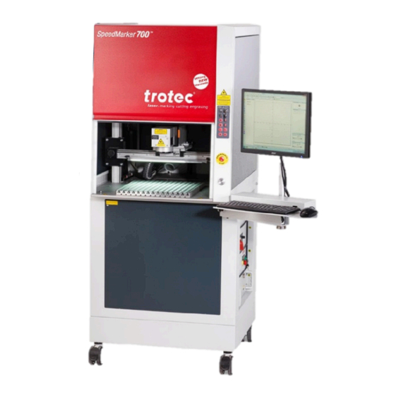
Introduction Introduction The SpeedMarker 700 fiber is a second generation of a high quality marking laser. The Yb fiber laser source means the system has an extremely long life cycle and minimal maintenance costs. The combination of a high quality galvanometer scanner and a fiber laser produce highly precise marking results in short marking times. -
Page 9: General Information
General Information General Information For the sake of readability, gender-neutral endings are not used in this operation manual. It is hereby expressly stated that all parts of the text where natural persons or groups of persons are mentioned refer to people of all genders. Information about this manual 2.1.1 Information about this manual... -
Page 10: Explanation Of Symbols
General Information This system may only be operated using devices and spare parts included in the scope of supply or the replacement or list of spare parts. Ancillary devices must be calibrated to meet the safety and operational requirements of the base machine (please contact your dealer or the manufacturer with any queries). -
Page 11: Liability And Warranty
Furthermore, Trotec Laser GmbH shall accept no liability whatsoever for damage caused by the use of non-original parts and accessories. Additionally, Trotec Laser GmbH shall not be held responsible for any personal injury or property damage, of an indirect or specific nature, consequential loss, loss of commercial profits, interruption to business, or loss of commercial information resulting from use of the equipment described in this manual. -
Page 12: Type Plate
General Information Notice The system should be returned and transported in the original packaging. Type plate The type plate contains information regarding the serial number, manufacturer, date of manufacture, connection values and consumption data. The type plate is located on the reverse side of the laser rack. Enter the serial number, model and year of construction of the machine here. -
Page 13: Safety
Safety Safety TO AVOID POSSIBLE HARM READ AND FOLLOW THESE INSTRUCTIONS. The machine is built at the time of it's development and production according to applicable, established technical rules and is considered to be safe to operate. Dangers can be caused by the machine if the machine: is operated by unqualified personnel, •... -
Page 14: Intended Use
3.1.1 Intended use The SpeedMarker 700 FL is a Class 2 laser marker as per DIN EN 60825-1 “Safety of laser products”. It is intended for integration in systems and lines. The product is intended exclusively for laser marking using the supplied marking soware. -
Page 15: Operating Modes
4 (US: class IV) and proper precautions need to be taken (see “Laser classification”). 3.1.6 Applicable safety regulations The following directives and guidelines must be observed to avoid hazards when operating Trotec laser systems: GUIDELINES/REGULATIONS 2006/42/EC... -
Page 16: Laser Safety
Laser classification The laser safety class indicates the risk potential based on the level of accessible laser radiation. The SpeedMarker 700 FL is a laser class 2 product and complies to the latest safety norms and regulations (IEC 60825-1). Class 1 The accessible laser radiation of Class 1 laser systems does not pose any hazard for the skin or eyes. -
Page 17: Areas Of Responsibility
Safety However, it is possible to suppress the natural eyelid closure reflex and stare into the class-2 laser beam for a time long enough for the eyes to get injured. Class 4 (US: class IV) Class 4 (US: class IV) high powered lasers (visible or invisible) considered to present potential acute hazard to the eye and skin for both direct and scatter (diffused) conditions. -
Page 18: Responsibilities Of The Operating Personnel
• The machine and its components, such as the lens and mirrors, are to be kept clean at all times. • Caution The adjustment of the beam path may only be carried out by service personnel of Trotec Laser GmbH. -
Page 19: Requirements For Operating An Service Personnel
If any warning and safety stickers are lost or damaged, the user is not able identify risks anymore, and there is danger of injury. – Replace lost or damaged labels immediately. – Contact your Trotec Laser GmbH dealer for details. - Page 20 Safety...
-
Page 21: Secondary (Indirect) Hazards
Safety Secondary (indirect) hazards 3.6.1 Fire hazard Warning Fire hazard Fire hazard from gas and processing of inflammable materials. – Do not operate the device without supervision. – Keep CO fire extinguisher ready at hand in the immediate vicinity of the device. If a main laser beam hits easily flammable material, e.g. -
Page 22: In Case Of Emergency
• Notice Aer a deletion, Trotec Technical Support must be involved before the system is put back into operation. WHAT TO DO IN THE EVENT OF AN ACCIDENT, FIRST AID If eye damage occurs due to laser radiation, the casualty must present to an ophthalmologist immediately. -
Page 23: Technical Data
Technical Data Technical Data The technical data sheet can be found in the appendix of this manual. Electrical requirements of the machine Caution Inadequate or inappropriate power sources can lead to machine damage and are not covered by any liability. Verify that the electrical outlet is capable of providing the proper voltage, frequency and amperage required by the laser machine described in this manual. - Page 24 Technical Data The requirements for the exhaust system and recommended Trotec exhaust systems for standard applications depend on the working table installed in the machine. Notice Connection has to be carried out by our Technical Support. Observe instructions for operation and maintenance according to the operating manual of the exhaust system.
- Page 25 Technical Data Notice The exhaust power available for the application will be reduced by e. g. bends, small hose diameters and long hoses. You should therefore note the following: – Avoid bends. – Keep hose as short as possible. – Use hose diameters as large as possible.
-
Page 26: Machine Overview
Machine overview Machine overview General overview FRONT VIEW SpeedMarker 700 SpeedMarker 700 RT 1 Laser safety glass (Observation window) 6 Emergency stop button 2 Safety door 7 Start button 3 Rolls (optional levelling feet) 8 Light grid 4 Operating panel 9 Partition panel 5 Monitor, keyboard, computer mouse 10 Rotary table... -
Page 27: Processing Area
Machine overview BACK VIEW ❶ Connection Exhaust system ❷ Connection Power supply SUPPLY CONNECTIONS The power cable can be connected via a power supply plug connection. Connect a suction hose with nominal diameter 45. Processing area The processing area is closed during the laser process. SpeedMarker 700 SpeedMarker 700 RT ❶... - Page 28 Machine overview DRILLING PATTERN T-SLOT PLATE...
-
Page 29: SoWare Controlled Z- And X-Axis
Machine overview HOLE PATTERN REVOLVING TRANSFER TABLE 5.2.1 Soware controlled z- and x-axis ❶ Limit switch le ❷ Limit switch right ❸ Axis drive... -
Page 30: SoWare Controlled Z-, X- And Y-Axis
Machine overview 5.2.2 Soware controlled z-, x- and y-axis ❶ Limit switch rear ❷Limit switch front ❸ Axis system General structure of the axes Each axis system consists of a linear servo axis with high precision. • The z and y axes are designed as a tandem axis. •... -
Page 31: Laser Rack
Machine overview ❶ Ventilation grille ❷ Main switch 5.3.2 Laser rack LASER RACK Number Description Types Main switch toggle switch System ready control lamp Shutter control lamp Laser busy control lamp Emergency stop button switch Error reset button Key switch switch... -
Page 32: Industrial Pc
Machine overview 5.3.3 Industrial PC ❶ CD/DVD drive ❷ Ventilation grille Safety devices MAIN SWITCH Base cover on the right: When the main switch is operated, the entire system is de-energized. • Laser is off. • ❶ Main switch EMERGENCY STOP BUTTON 1. - Page 33 Machine overview Second priority: prevention of damage or destruction of machine or material. Immediately switch off the circuit. • Laser beam is interrupted by the shutter. • All movements are stopped. • The triggering of the emergency stop function is indicated by a fault message. •...
- Page 34 Machine overview SAFETY SWITCH ON THE SAFETY DOOR Observation window: The light blue observation window in the front door is made of a laser protection filter according to DIN EN 201, which is made of a special material that is adapted to the laser type and absorbs the laser radiation. If the window is damaged, it must be replaced.
-
Page 35: Before Commissioning
Before commissioning Before commissioning Read the operating manual and ensure it is accessible at all times. • The ambient temperature must be between +15 °C and +25 °C (59 °F and 77 °F) and not exceed the relative humidity • of 45-65% (non-condensing). -
Page 36: Transport And Storage
Transport and Storage Transport and Storage Transport conditions When transporting outside, always transport in a covered vehicle or one with sufficient weather-proofing. • Protect the machine against transportation damage using straps and inserts, and leave sufficient distance between • other transported items. Ambient temperature for transportation: •... -
Page 37: Transport Inspection And Reporting Of Defects
Transport and Storage Transport inspection and reporting of defects Immediately aer receipt inspect the delivery to ensure that it is complete and has not suffered any damage. • If any transport damage is visible, do not accept the delivery, or accept it only with reservation. •... -
Page 38: Setup And Installation
Setup and installation Setup and installation For your safety Notice The setup has to be carried out by Technical Support. Temperature and humidity Ambiente conditions Operating temperature (ambiente temperature): +15 °C to +25 °C (59 °F to 77 °F) Relative humidity: 45% to 65%, non-condensing If the system has been exposed to large temperature fluctuations, it must first be brought back to room temperature •... -
Page 39: Unpacking The System
Setup and installation Unpacking the system REMOVE TRANSPORT PROTECTION: 1. Push up the high safety door ❶slightly. 2. Remove the screw of the fairing ❷on the le side. 3. Open the cover.. Caution Risk of crushing fingers! If necessary, close the cover carefully, paying attention to your fingers. -
Page 40: Mechanical Installation
Setup and installation 4. Remove foam fuses❸. 5. If available, remove safety tape ❹at the galvo scanner. Mechanical installation The correct, stable and reproducible alignment of the working head in relation to the workpiece to be marked is a prerequisite for faultless marking results. The marking head should therefore be installed with appropriate care. FIBER OPTIC CABLE The working head is connected to the actual laser source in the laser rack via an approx. -
Page 41: Electrical Installation
Setup and installation SOFTWARE INSTALLATION The soware will be installed by starting the SETUP.exe from the soware-CD. Please follow the steps on the screen. The correct configurations files must be installed aer the soware setup is finished. The installation guide is enclosed in the accessory. - Page 42 If no external panel is connected, the supplied connector must be used with the bridging devices. X61 – Exhaust system This connector is used to control, start and stop a Trotec extraction unit. Only use the original cable supplied. X71 – Start / Stop The X71 connector may be used to send start and stop signals via an external controller or receive a signal from the laser.
- Page 43 Setup and installation For the “Start” and “Stop” Signal external 24VDC are needed. COM7/X Connection X-Axis COM8/Y Connection Y-Axis COM9/Z Connection Z-Axis COM10 Reserved COM11/B Connection B-Axis COM12/A Connection A-Axis Connection between PC and Laserrack Warning The maximum load of each of the digital 24V outputs on the interface is 100mA. A short circuit of the outputs must be avoided as it will damage the respective inputs.
- Page 44 Setup and installation The inputs have to be provided with a 5V - 24V potential. • For “ON”, the first PIN (e.g. PIN1) hast to be provided with 24V and the second PIN (e.g. PIN2) has to go to ground to •...
-
Page 45: Overview Pc Interface (Back Side)
Setup and installation APPLICATION EXAMPLES Input with switch and external 24V source at input "IN9". Supply of a lamp with 24V by activating “OUT10”. 8.6.2 Overview PC interface (back side) The machine is connected to the Ethernet via a cable connection from the LAN interface on the rear of the PC rack to the LAN interface on the laser rack. -
Page 46: Mains Connection
Setup and installation 8.6.3 Mains connection Laser rack and PC have a cold device socket on the rear for the cold device cables supplied. Before commissioning, it is essential to check whether the laser rack is configured to the mains voltage and frequency. The configuration of the laser rack is given on the type plate or on the warning label above the IEC connector. - Page 47 Setup and installation X71 – Start / Stopp I/O Input/Output...
-
Page 48: Operation
Operation Operation Installation inspection The following points must be checked to ensure correct installation: Correct power supply connections and fuses. • Complete and correct mechanical and electrical installation. • Check that the mechanical and electrical installation is complete and correct Input voltages. •... -
Page 49: Control Elements
Operation Control elements ❶ LEDs ❷Keypad ❸Emergency stop button ❹ Start button Status Description POWER green Power supply is switched on green Laser control is switched on LASER green Laser is active ERROR Interference, not yet acknowledged AUTO green Automatic mode is active... - Page 50 Operation Key switch Selection of manual or automatic operation Button Lighting in the machining area Lighting Safety door open Move safety door upwards Safety door closed Move safety door down Button backward (Y) Move laser to the back Button right (X) Move laser to the right Button le...
-
Page 51: Manual Operation
Operation 9.3.1 Manual operation MANUAL CONTROL OF SAFETY DOOR Button: Safety door open Button: Safety door closed SOFTWARE CONTROLLED X- AND Z-AXIS (OPTIONAL: Y-AXIS) (5) y-axis back (optional), moving the y-axis backward. (6) x-axis right (optional), traverse the x-axis to the right (7) x-axis le... -
Page 52: Power On/Off
Operation Power On/Off 1. Press the main switch (1) on the laser rack. → The shutter is closed. The main switch and the two status lamps on the marking head illuminate in yellow. 2. Put the key in the key switch (7) (vertically) and turn 90° to the right. 3. -
Page 53: Emission Indicator
Operation SEQUENCE OF AUTOMATIC MODE SpeedMarker 700 1. Open door in manual mode. 2. Start automatic sequence with the “Start” key 3. The safety door closes. 4. The marking process runs automatically. 5. Marking process is completed. 6. The safety door opens. 7. -
Page 54: Focusing
Operation Emission indicator status yellow - shutter is closed, no laser power output. Emission indicator staus red - shutter is open, output of laser power possible. Warning Laser If the device is switched on or the safety shutter is open there is a danger of laser radiation. –... -
Page 55: Options
Operation Working distance (A) Focal length F = 100 154,0 mm F = 160 215,0 mm F = 210 271,5 mm F = 254 322,0 mm F = 330 391,5 mm F = 420 501,5 mm Options 9.8.1 SpeedMarker “DS” Dynamic Shiing The SpeedMarker DS enables very fast and precise focusing without mechanical movement of the marking head. -
Page 56: Projection/Virtual Rotary
Operation WORK VOLUME Information Further and detailed information on the use of the functions can be found in the soware manual. 9.8.2 3D-Projection/Virtual Rotary In addition to the Focus Shi function, it is possible to activate the “3D-Projection” option for xyz-axis systems by means of a license key. -
Page 57: Ingetration / Connection
Ingetration / Connection Ingetration / Connection 10.1 Switching sequences Switching sequence diagrams are provided for various standard processes which indicate the interplay of the individual signals. - Page 58 Ingetration / Connection...
-
Page 59: Maintenance
Maintenance Maintenance 11.1 Safety notes Caution Before any maintenance work takes place, ensure that the power supply has been switched off and the system is de-energised. Notice All maintenance work must be carried out according to the safety regulations. In order to ensure the maximum availability and lifetime of the system, we recommend you regularly check the filter system and ventilation and keep the surrounding area clean. -
Page 60: Cleaning The Optics
Maintenance 2. Remove both screws and open the cover. Change the filter pad. 11.3 Cleaning the optics This system is fitted with high quality optical components, which under normal operating conditions are maintenance free for their lifetime. However, it may be necessary to clean output lenses, e.g. the scanner flat field lens (f-theta objective) if it becomes covered in dust or fumes. -
Page 61: Troubleshooting
This chapter should assist maintenance personnel with the identification and resolution of operational faults based on error messages and symptoms. Danger Maintenance and repair work should only be carried out by Trotec Laser GmbH or one of its authorized personnel under observation of the safety regulations. 12.1... -
Page 62: Possible Error Messages
The Reset signal (X11) or the reset button on the laser rack are used to acknowledge an error. In order for the system to be reset, the error or the corresponding input signal must be acknowledged. Warning System errors which cannot be reset or which indicate a hardware error should only be resolved by Trotec Laser GmbH trained service personnel. Error message Cause Card off... - Page 63 Troubleshooting Error message Cause Required shutter position.
-
Page 64: Contact Details
Contact details Contact details TECHNICAL SUPPORT In case of questions, contact our experienced Technical Support in your local area. For global service contact numbers and further information please see our website, section "Support": www.troteclaser.com When calling, please make sure that the machine is in your immediate vicinity, and that you have the following information ready (see response form): At which working process did the problem occur? What you have done so far to correct the problem. -
Page 65: Disassembly
Disassembly Disassembly Warning Danger of injury when disassembling the machine. There is danger of injury when disassembling the machine. Always wear suitable protective clothing (e.g. safety goggles, safety shoes, safety gloves). Warning Dangerous electrical voltage Electric current. The machine must be disconnected from the main power supply. Notice –... -
Page 66: Disposal
Disposal Disposal Disposal Do not dispose of the machine with domestic waste! Electronic devices have to be disposed of according to the regional directives on electronic and electric waste disposal. In case of further questions, please ask your supplier. In case of disassembly, use suitable tools to dismantle the unit into individual parts. Sort the individual parts and have them disposed of professionally. -
Page 67: Appendix
Appendix Appendix... -
Page 69: Datasheet 8041 Speedmarker 700
Technical Datasheet SpeedMarker 700 (8041) Laser Wavelength 1.064 nm Laser source Pulsed Yb-fiberlaser Power stability better ± 5 % Cooling active fan cooled Laser type 20W Fiber 20W MOPA 30W Fiber 50W Fiber 100W MOPA Maximum laser power 100W Pulse frequency (kHz) 1-600 1-4000 1-600... - Page 70 Technical Datasheet System specification Norm CDRH Lasersafety; Laserclass 2; CE [EN 60825-1] Dimensions [W x H x D in mm] 784 x 2134 x 1031 Software Speedmark; Directmark Printerdriver Axis software controlled Supported mono fonts ISOCT, RomanS,SOKOL Supported fonts all installed TrueTypeFonts Australian Post;...
-
Page 71: Datasheet Smart Adjust
SpeedMark Vision - Smart Adjust Technical Datasheet SpeedMark Vision – Smart Adjust Integrated camera system for user friendly and precise positioning of markings directly on the product. Camera image is shown di- rectly in the GUI of the laser software Camera und Lens Sensor type CMOS... - Page 72 SpeedMark Vision - Smart Adjust Technical Datasheet Size of camera image (depending on lens) F-Theta lens laser F-100 F-160 F-254 F-330 F-420 Marking field laser 70 x 70 120 x 120 190 x 190 240 x 240 310 x 310 [mm] 8,5 mm lens [mm] ~ 140 x 100...
Need help?
Do you have a question about the SpeedMarker 700 FL and is the answer not in the manual?
Questions and answers