Table of Contents
Advertisement
Quick Links
Advertisement
Table of Contents

Subscribe to Our Youtube Channel
Related Manuals for Trotec Speedy 400


Summary of Contents for Trotec Speedy 400
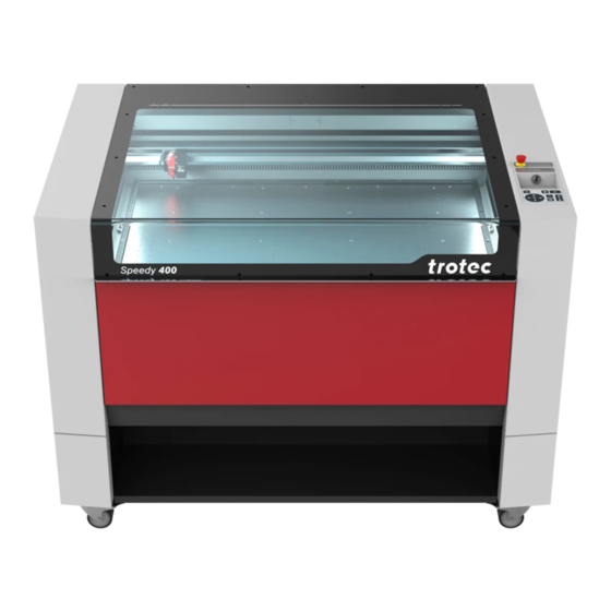
- Page 1 Speedy 400 Operating manual 8070 OM 8070_1.12_EN (07/2021) ENGLISH (Translation)
- Page 2 +31 850 70 51 55 +48 22 339 35 39 +52 55 5351-7252 support@troteclaser.nl serwis_pl@trodat.net mexico@troteclaser.com Trotec Laser (XIAMEN) CO., LTD. #5 GuAn Road South, MaXiang Trotec Laser Inc. Rubber Stamp & Engraving Town +1 866 226 8505, Option 2...
- Page 3 Trotec Laser GmbH Freilingerstraße 99 4614 Marchtrenk, Austria General contact to Technical Support: Tel.: +43 7242 239-7000 E-mail: techsupport@troteclaser.com WWW.TROTECLASER.COM...
- Page 4 Technical Changes Technical specifications are subject to change without notice. Trotec Laser GmbH reserves the right to improve or modify any of the products without prior notice. © Copyright This documentation with all illustrations is intellectual property of Trotec Laser GmbH. The entire documentation is given to the user for personal use only.
-
Page 5: Table Of Contents
Content Content General Information....................... 8 Information about this manual..........................8 Explanation of symbols...............................8 Liability and warranty..............................9 Scope of delivery (standard configuration)......................10 Type plate..................................10 Safety........................... 11 General safety notes..............................11 2.1.1 Intended use................................11 2.1.2 Improper use................................12 2.1.3 Residual risk................................12 2.1.4 Machine modification............................ - Page 6 Content 2.8.5 Protective measures for damaged optics......................24 In case of emergency..............................25 Technical Data......................26 Dimensions and weight............................26 Electrical requirements of the machine........................ 27 Exhaust system requirements..........................27 List of materials................................29 Machine overview......................33 General overview................................33 Ruby server status LED..............................36 Front door..................................37 Tables (multifunctional table concept)........................37 Lens(es)..................................38 Nozzles..................................39...
- Page 7 Rotary attachment..............................62 7.9.2 Installation and startup............................63 7.9.3 Mounting the work piece in the rotary attachment..................63 7.9.4 Gas-kit light................................65 7.9.5 Trotec Vision Print&Cut............................66 7.9.6 Temperature sensor............................... 67 7.9.7 Screw feet................................. 68 Maintenance......................... 69 Safety notes................................. 69 Maintenance plan...............................70 Change the filter mat..............................71...
-
Page 8: General Information
General Information General Information For the sake of readability, gender-neutral endings are not used in this operation manual. It is hereby expressly stated that all parts of the text where natural persons or groups of persons are mentioned refer to people of all genders. Information about this manual Before beginning any work on the machine, read this manual completely and carefully. -
Page 9: Liability And Warranty
Furthermore, Trotec Laser GmbH shall accept no liability whatsoever for damage caused by the use of non-original parts and accessories. Additionally, Trotec Laser GmbH shall not be held responsible for any personal injury or property damage, of an indirect or specific nature, consequential loss, loss of commercial profits, interruption to business, or loss of commercial information resulting from use of the equipment described in this manual. -
Page 10: Scope Of Delivery (Standard Configuration)
General Information Scope of delivery (standard configuration) 1. Laser machine 2. Storage medium 3. Focusing tool(s) (according to lens order) 4. Cleaning kit for optics 5. Nozzles (ø3 and ø7) 6. Lenses according to order 7. Working tabel according to order 8. -
Page 11: Safety
Operate the machine only in technically flawless condition and when it fully complies with the EC Machinery Directive. For material details see chapter "Materials" or contact your local Trotec representative, or our Technical Support. The intended use of this machine also includes that all personnel involved in installation, set-up, operation maintenance and repair of the machine must have read and understood the operating manual and in particular the “Safety”... -
Page 12: Improper Use
Use of the machine for any purposes other than those intended or described in the present manual is regarded as improper and therefore prohibited. Trotec Laser GmbH will not accept any liability for damage caused by improper use. The operator is solely liable for all damages caused by improper use. -
Page 13: Applicable Safety Regulations
4 (US: class IV) and proper precautions need to be taken (see "Laser classification"). 2.1.6 Applicable safety regulations The following directives and guidelines must be observed to avoid hazards when operating Trotec laser systems: GUIDELINES/REGULATIONS 2006/42/EC... -
Page 14: Laser Safety
Safety Laser safety 2.2.1 Laser classification The laser safety class indicates the risk potential from accessible laser radiation. The laser system is a Class 2 (US: Class II) laser marking system as per IEC 60825-1 "Safety of Laser Product". The integrated laser source is a Class 4 (US: Class IV) laser marking system according to IEC 60825-1 and identified as such. -
Page 15: Areas Of Responsibility
Safety Class 2 (US: class II) The accessible laser radiation of Class 2 (US: Class II) laser systems does not pose any hazard for the skin. Diffuse reflections as well as any short-term irradiation of the eyes (exposure time max. 0.25 seconds) also pose no risk due to the low output power. -
Page 16: Responsibilities Of The Operating Personnel
• The machine and its components, such as the lens and mirrors, are to be kept clean at all times. • Caution The adjustment of the beam path may only be carried out by service personnel of Trotec Laser GmbH. -
Page 17: Requirements For Operating An Service Personnel
Control/operation/other activities Qualified personnel or Qualified personnel are those who can judge the (e.g. troubleshooting, maintenance) Trotec service technicians work entrusted to them and detect potential risks based on their occupational training, knowledge and experience as well as their understanding of... -
Page 18: Warning And Information Labels
If any warning and safety stickers are lost or damaged, the user is not able identify risks anymore, and there is danger of injury. – Replace lost or damaged labels immediately. – Contact your Trotec Laser GmbH dealer for details. -
Page 19: Safety Devices
Safety and protection devices must be fully functional at all times. – In case of assumed or presumed damage of safety devices, disconnect the machine from the mains. – Damaged safety and protection devices need to be replaced by a Trotec technician immediately. Technical protective measures 2.7.1 Main switch Pressing the main switch on the backside of the machine to disconnect the machine from the mains power supply. -
Page 20: Emergency Stop Button
Safety TEMPERATURE SENSOR ALARM ACKNOWLEDGEMENT Press any key on the keypad to acknowledge the alarm. Notice The signal tone sounds again and again until the temperature returns to normal. Alternatively, switch off the laser system and check the temperature sensors. 2.7.4 Emergency stop button Pressing the emergency stop button immediately switches off... -
Page 21: Acrylic Top Lid
Safety 2.7.6 Acrylic top lid The type of acrylic top lid depends on the laser type. It protects the operator from uncontrolled emission of laser radiation. 2.7.7 Side cover The side panels protect from laser light and must always be closed and properly attached. 2.7.8 In case of safety device malfunction Actual or presumed damage to the safety devices can cause injury or damage. -
Page 22: Gases, Fumes And Dust
Safety 2.8.2 Gases, fumes and dust Depending on the materials being processed and the parameters selected, laser processing may generate gases, fumes, aerosols or dust. Depending on the material, such by-products may be toxic. In individual cases, the reaction products may be electrically conductive dusts. - Page 23 Safety LASER BEAM REFLECTION The reflecting law is valid for the reflection of the laser radiation: Angle of incidence = failure corner No. Description Directed reflection: Reflected ray on smooth surface. Directed reflection: Reflected ray on sloping surface. Diffuse reflection: Reflected ray on rough surface. Directed reflection: Horizontally reflected ray on smooth surface.
-
Page 24: Information About Damaged Optics
Safety 2.8.4 Information about damaged optics Warning Damage to optics. Soiled optics absorb laser radiation and can thus be destroyed. Broken or damaged lenses as well as thermal decomposition of lenses release particles which cause serious damage to the health. –... -
Page 25: In Case Of Emergency
• Notice Aer a deletion, Trotec Technical Support must be involved before the system is put back into operation. WHAT TO DO IN THE EVENT OF AN ACCIDENT, FIRST AID If eye damage occurs due to laser radiation (if the MPD values are exceeded), the casualty must present to an •... -
Page 26: Technical Data
Technical Data Technical Data The technical data sheet can be found in the appendix of this manual. Dimensions and weight Description Dimension Length 1428mm (56.22 inch) Width 952* mm (38.5 inch)* Height 1050 mm (41.5 inch) * Without exhaust hose connection, gas-kit light and the signal light on the back of the machine. Weight (depends on the machine type): 335 bis 350 kg (739 to 772 lbs.) -
Page 27: Electrical Requirements Of The Machine
Technical Data Electrical requirements of the machine Laser power 55–80 W (TL4 CO 85–100 W (TL6 CO 105–120 W (TL8 CO 20-50 W (fiber) 20-50 W (fiber) 20-50 W (fiber) Voltage 230 V~ 115 V~ 230 V~ 230 V~ Fuse 8A (T)* 16A (T)* 12A (T)*... - Page 28 The requirements for the exhaust system and recommended Trotec exhaust systems for standard applications depend on the working table installed in the machine.
-
Page 29: List Of Materials
Technical Data Notice The exhaust power available for the application will be reduced by e. g. bends, small hose diameters and long hoses. You should therefore note the following: – Avoid bends. – Keep hose as short as possible. – Use hose diameters as large as possible. - Page 30 Technical Data Plastic ✓ ✓ ✓ ✓ ✓ ✓ Acrylonitrile Acrylnitril- butadiene styrene ButadienStyrol- (ABS) Copolymer (ABS) ✓ ✓ ✓ ✓ ✓ ✓ Acrylic/PMMA, i.e. Acryl(PMMA), z.B. Plexiglas® Plexiglas® ✓ ✓ ✓ ✓ ✓ ✓ Rubber Gummi (Stempelgummi) ✓ ✓ ✓...
- Page 31 Technical Data Miscellanious ✓ ✓ ✓ ✓ Wood Holz ✓ ✓ ✓ ✓ Mirror Spiegel ✓ ✓ Stone Stein ✓ ✓ ✓ ✓ ✓ ✓ Paper (white) Papier (weiß) ✓ ✓ ✓ ✓ ✓ ✓ ✓ Paper (colored) Papier (farbig) ✓...
- Page 32 You have additions for further materials for us or in your opinion a material was not listed. We recommend performing a material processing test with the above mentioned material, using the appropriate configuration. Trotec Laser GmbH assumes no responsibility for any consequences of laser processing in any application, especially with medical or pharmaceutical applications.
-
Page 33: Machine Overview
Machine overview Machine overview General overview Description Description Top lid Keypad X-axis Front door Emergency stop button Laser head Key switch Working table USB ports LED Interior lighting Touch display Ruby server status LED... - Page 34 Machine overview Description Description Connector for exhaust tube (working area) Type plate Cover for laser source Cover of power supplies and filter mat Connector for exhaust tube (working table)
- Page 35 Machine overview Description Description Connector for exhaust tube Service plug connector Mains connection Signal horn of the temperature sensor Fuse I/O interface Main switch Wifi dongle...
-
Page 36: Ruby Server Status Led
Machine overview Ruby server status LED The Ruby server status LEDs are located on the le side above the LED interior lighting inside the laser machine. Description ❶ Green: power ❷ Yellow: activ ❸ Reset button... -
Page 37: Front Door
Machine overview Front door Loading and unloading of heavy and bulky parts or replacement of the table is very comfortable thanks to the front door that can be opened downwards. Notice The door is interlocked, therefore it must be closed before any laser operation is possible. -
Page 38: Lens(Es)
Machine overview Notice All table variants rest on the base frame. However the ferromagnetic engraving table may also be placed directly on the mounting frame without the base frame. Maximum material load is: – For static loads up to 220 lbs (100 kg). –... -
Page 39: Nozzles
Machine overview Fiber Flexx 2.5'' silver Part number: 85975 4.0'' blue Part number: 90026 4.0'' CL purple Part number: 143502 Nozzles Ø 3 mm Short nozzle with small hole. Ø 7 mm Short nozzle with big hole. -
Page 40: Transport
Transport Transport Safety notes Warning Risk of injury There is risk of injury from falling parts during transport, loading and unloading of the machine. – Follow the safety notes. Observe the safety notes to avoid damage to the machine from improper handling during transport: Always move the machine with utmost care and attention. -
Page 41: Temperature And Humidity
Transport OBSERVE THE PACKAGING SYMBOLS: NOTE THE SHOCKWATCH SIGN: Temperature and humidity Transport conditions Transport temperature (ambiente temperature): -10 °C to +40 °C (14 °F to 104 °F) Relative humidity: Maximum 70%, non-condensing Avoid high temperature fluctuations. • Storage conditions Storage temperature (ambiente temperature): 0 °C to +30 °C (32 °F to 86 °F) Relative humidity:... -
Page 42: Required Tools For Unloading And Transport
Transport Required tools for unloading and transport REQUIRED TOOLS: Unloading - Forkli • Transport - Pallet truck • Place of storage Keep the machine sealed in its packaging until it is assembled or installed. • The storage location must be dry, free of dust, caustic materials, vapors and combustible materials. •... -
Page 43: Relocation Of The Machine
Transport Caution The lens unit should be unpacked only aer installation of the machine. The lenses are high-quality optical components which must be kept clean in order to ensure optimum marking results. Never touch the lenses with bare fingers. STEPS: 1. - Page 44 Transport Notice If you would like to relocate the machine, contact our experienced Technical Support in your local area.
-
Page 45: Setup And Installation
Setup and installation Setup and installation For your safety Notice The setup has to be carried out by Technical Support. Temperature and humidity Ambiente conditions Operating temperature (ambiente temperature): +15 °C to +25 °C (59 °F to 77 °F) Relative humidity: 45% to 65%, non-condensing If the system has been exposed to large temperature fluctuations, it must first be brought back to room temperature •... -
Page 46: Space Requirements
Setup and installation Space requirements Ensure there is shielding or sufficient clearance to or from the wall and neighboring objects. Setup OBSERVE THE FOLLOWING STEPS: 1. Transport the machine to the installation location according to the specifications stated in the chapter “Transport”. 2. -
Page 47: Connections
Setup and installation Connections 6.5.1 Mains connection Connect the end of the mains connection cable to the main connection socket. Warning Current Wrong voltage can cause damage to the machine. Do not operate the machine, if the mains voltage does not match the voltage required by the exhaust system, as this may cause damage to the machine. -
Page 48: Computer Connection
Setup and installation 6.5.3 Computer connection Connect the machine to the local network port using a LAN cable or plug in the optional Wifi dongle on the back of the machine. The network settings must be set up when the machine is first started. Information Information on the connections can be found in the chapter "General... -
Page 49: Chiller
Setup and installation Connecting: 1. When using an original Trotec exhaust system, also connect this, using the exhaust connection cable included, to the exhaust cable connection on the laser. 2. Plug the ends of the exhaust hose into the exhaust nozzle that is intended for this purpose on the exhaust system and on the laser. - Page 50 Notice The conductivity of the water must not exceed 1000 μS. This value will not be reached if mixing the distilled water and additive accurately. A conductivity meter is available on request from Trotec Laser GmbH. Water replacement must be carried out once a year. Empty the cooling unit, clean it with distilled water, fill it with fresh distilled water and add new additives.
-
Page 51: Operation
Operation Operation Warning Personal injury or damage to property due to improper operation. Improper operation can lead to serious personal injury or damage to property. – Work on the laser machine may only be carried out by authorized and instructed personnel familiar with the operation of the machine, observing all safety regulations. - Page 52 Operation SWITCH ON: 1. Switch on the main power supply using the main switch on the rear of the machine. The built-in Ruby server starts. 2. Turn the key switch to the right into the vertical position to activate the touch display.
-
Page 53: Control Panel And Keypad
Operation SWITCH OFF: 1. Turn the key switch to the le. The touch display switches off, the axes are de-energized and the server remains active. 2. Switch off the main power supply to the machine by operating the main switch on the rear of the machine. Control panel and keypad The control panel is the whole unit of the machine control. -
Page 54: Control Panel
Operation Control panel ❶ Emergency stop button ❷ Key switch ❸ USB ports ❹ Display ❺ Keypad ❻ RFID sensor... -
Page 55: Keypad
Operation Keypad ❶ Start/Pause/Repeat-button ❷ Stop-button ❸ Status indicator LED On: The machine is processing data. ❹ Laser head control button X/Y travel distance in X-direction • travel distance in Y-direction • ❺ RFID-Control display ❻ Working table control button Z Up-button •... - Page 56 Operation Start/Pause/Repeat-button Start: Press this button to start a job. • Pause: Press this button to pause the job which is currently being • processed. Press this button again to continue the job. • Repeat: Press this button aer a job was finished to repeat the actual •...
- Page 57 Operation Working table control button Z Press one of these buttons to manually move the working • table up or down (travel distance in Z-direction). By simultaneous pressing of the Up-button + Down-button, • the activation of the automatic focusing starts and the working table is moving automatically upwards.
-
Page 58: Usb Ports
Operation USB ports There are two USB ports on the control panel. Charge (max. 2A) = Charging port Data (500mA) = USB port (USB stick, HDD,..) Lense placement 1. Loosen lens by turning the clamping ring inwards. 2. Remove lens. 3. -
Page 59: Focusing Methods
Operation 5. Insert the lens with the lettering facing up, either above or below the clamping ring depending on the lens type. 6. Fixate the lens with the clamping ring. THE FOLLOWING LENSES MUST BE INSERTED BELOW THE CLAMPING RING: 1.5'' 2.0'' Notice... -
Page 60: Focus Tool
Operation Caution If workpieces with more than 66.14 lbs (30 kg) have been placed on the table, the table must not be moved up or down anymore as this might damage the mechanics of the machine. It is mandatory to focus on the height of the material before loading material of 66.14 lbs (30 kg) and above. -
Page 61: Sonar Technologie
Operation Notice Using a flexx lens the focus point differs depending on the laser source. Note when focusing using a focus tool, the standard focus tool supplied with a flexx lens is always adjusted for a fiber laser source. Therefore it must only be used in conjunction with a fiber laser source. 7.8.2 Sonar Technologie Caution... -
Page 62: Options
Operation Options 7.9.1 Rotary attachment The Rotary attachment is used to engrave cylindrical workpieces. Caution Damage to electronics. Inserting or removing the Rotary attachment while the machine is turned on may irreparably damage the electronics. Switch off the machine before inserting or removing the Rotary attachment. Rotary attachment with cones: Rotary attachment with rolls: Max. -
Page 63: Installation And Startup
Operation 7.9.2 Installation and startup ❶ Connection for the rotary attachment ❷ Centring pin ❸ Table base frame 1. The machine must be switched off. Warning Current If the rotary attachment is connected during operation, the connections and the electronics will be damaged. Such damage is excluded from the warranty. - Page 64 Operation Levers for fixation of height and angle 3. Loosen the slider by using the lever in order to clamp the workpiece between the two cones or rolls. Slider inclusive lever 4. Switch on the laser. The axis automatically moves over the middle of the rotary attachment. 5.
-
Page 65: Gas-Kit Light
Operation 7.9.4 Gas-kit light The Gas-Kit light allows an external compressed air to be connected to the machine to improve dust transport during laser processing and provide additional protection for the lens. The Gas-Kit light is located on the back of the machine. -
Page 66: Trotec Vision Print&Cut
Only connect dry and oil-free compressed air. If you have any questions, please contact our experienced technical support in your area. 7.9.5 Trotec Vision Print&Cut The Vision option is a camera on the laser processing head that reads the registration marks on the plate material, thus detecting and compensating for distortions in the print. -
Page 67: Temperature Sensor
Operation In the control soware, under the settings tab, the camera option must be checked to adapt the acceleration and travel to the weight on the processing head. Notice When the camera is removed, the hook can be removed to return the speed and travel distance to maximum. -
Page 68: Screw Feet
Operation 7.9.7 Screw feet The height-adjustable feet are available as an option. They compensate for unevenness and give the machine better stability. -
Page 69: Maintenance
Maintenance Maintenance Safety notes Danger Improper maintenance can cause serious injury or damage. Maintenance may be carried out only by authorized, trained personnel who are familiar with how to operate the machine and in strict observance of all safety notes. Danger Risk of fire or explosion. -
Page 70: Maintenance Plan
Maintenance Maintenance plan System Components Daily Weekly Half-yearly Yearly Lens, ✓✓ mirror #4 ✓✓ Mirror #2 and mirror #3 Ultrasonic sensor ✓✓ (option) ✓✓ Working table and rulers. Vent slots of exhaust box. ✓✓ (inside the machine) Entire working area. ✓... -
Page 71: Change The Filter Mat
7. Clean the transparent acrylic top lid using a dry or slightly damp cotton cloth. Do not use paper towels as they could scratch the acrylic. 8.4.2 Optics in general Trotec Laser GmbH recommends to use the cleaning set enclosed. Alternatively, use high-quality cotton swabs together with the provided cleaning liquid. -
Page 72: Lens
Maintenance Notice The following cleaning products are available as accessory parts: – Lens cleaning cloth – Lens cleaning liquid 8.4.3 Lens Warning Damage to optics. Soiled optics absorb laser radiation and can thus be destroyed. Broken or damaged lenses as well as thermal decomposition of lenses release particles which cause serious damage to the health. -
Page 73: Cleaning The Mirrors
Maintenance Notice Trotec Laser GmbH recommends to use the following cleaning products, which are available as accessory parts: Lens cleaning cloth (part number 69249) and lens cleaning liquid (part number 69248). 8.4.4 Cleaning the mirrors Caution Make sure that you do not touch the mirror with your fingers, since this would greatly reduce the service life of the mirror. -
Page 74: Ultrasonic Sensor (Sonar Technology Tm )
Maintenance CLEANING THE MIRROR #4 1. While holding the mirror, loosen the two knurled screws (1) and li the mirror from the mirror holder. Caution Make sure that the mirror does not grind over the mirror holder, as it can be scratched very easily. 2. -
Page 75: Troubleshooting
Troubleshooting Troubleshooting This chapter should enable the maintenance personnel to identify and resolve operational faults based on error messages and symptoms. Warning Risk of fire from incorrect parameter settings. Laser operation with incorrect parameter settings such as power settings, speed or frequency can result in flame formation. - Page 76 Troubleshooting Problem Possible cause Remedy The size to be engraved or cut does Raster correction ON in the Switch off raster correction in • • not match the size in CorelDraw. soware. the soware (settings/advanced options/laser tab). Wrong size settings in the printer •...
-
Page 77: Contact Details
Contact details Contact details TECHNICAL SUPPORT In case of questions, contact our experienced Technical Support in your local area. For global service contact numbers and further information please see our website, section "Support": www.troteclaser.com When calling, please make sure that the machine is in your immediate vicinity, and that you have the following information ready (see response form): At which working process did the problem occur? What you have done so far to correct the problem. -
Page 78: Disassembly
Disassembly Disassembly Warning Danger of injury when disassembling the machine. There is danger of injury when disassembling the machine. Always wear suitable protective clothing (e.g. safety goggles, safety shoes, safety gloves). Warning Current Electric current. The machine must be disconnected from the main power supply. Notice –... -
Page 79: Disposal
Disposal Disposal Disposal Do not dispose of the machine with domestic waste! Electronic devices have to be disposed of according to the regional directives on electronic and electric waste disposal. In case of further questions, please ask your supplier. In case of disassembly, use suitable tools to dismantle the unit into individual parts. Sort the individual parts and have them disposed of professionally. -
Page 80: Appendix
Appendix Appendix... - Page 81 Acceptance report Dear customer! We request your confirmation of properly completed transfer of the machine. Please transmit a copy of this document - filled out and signed by an authorized company representative - to an employee of our sales affiliate for forwarding to the manufacturer. Please check applicable items: Machine parts checked for shipping damage.
- Page 82 Training verification form Trainee: Trainer: Date of Training: The employee named above was instructed in the operation of the ........laser system. Especially the following topics were covered: Machine function Danger areas Warnings Position of the Emergency stop button Personal protective equipment Operating equipment Workflow Setting-up...
-
Page 83: Dok Iiir
Response form Dear customer! In case of any trouble with the machine, please provide the following information and additional- ly create a service file. Contact details Machine data Name: Serial number: Country: Layout Software: Phone: E-mail: Date: Description of the problem Does an error message show up on the PC , and if so, which? What happened before the error occurred? (Thunder and lightning, Windows-Update...) What attempts were made to solve the problem? -
Page 84: Datenblatt_Speedy400C-8070_De
Technical Datasheet Speedy 400 Laser engraving system Mechanics Working area 1016 x 610 mm (40 x 24 inch) Loading area standard 1096 x 698 mm (43 x 27.4 inch) 305 mm (12 inch) with 1.5 inch, 2.0 inch lens 292,5 mm (7.7 inch) with 2.0 inch clearance lens, 2.5 inch lens Max. - Page 85 Additional to the rolls, for a good standing on the ground 1.1.1.1.1.1.1 Registration marks detection and compensation system Trotec Vision Print&Cut Max. working area without camera: 1016 x 610 mm (40 24 inch) Max. working area with camera: 1004 x 610 mm (39.5 24 inch)
- Page 86 Technical Datasheet Laser Laser system CO Sealed-off laser, maintenance free, air cooled, wavelength 10.6 µm Laser power CO 60, 80, 100 and 120 W Dimensions & weight 1428 x 952* x 1050 mm (56.2 x 38.5* x 41.5 inch) Width x Depth x Height * without exhaust hose connection and gas-kit light on the back of the machine, open top lid Weight...
- Page 89 The basic concept and the features for safe operation of the machine are not influenced by the amendment and remain unchanged. Marchtrenk, 14. July 2021 Place, date pp Hagen Strasser Head of Research and Development www.troteclaser.com Trotec Laser GmbH, Freilinger Straße 99, 4614 Marchtrenk, Austria www.trotec-materials.com...
Need help?
Do you have a question about the Speedy 400 and is the answer not in the manual?
Questions and answers