
Summary of Contents for Electron E-ROBOT+3 Series
- Page 1 POWDER COATING EQUIPMENT USER’S MANUAL E-ROBOT+3 SER I E S Check our product electron.com.tr + info@electron.com.tr online...
- Page 2 © 2023 Sistem Teknik Makina A.Ş. All rights reserved. 10010 St. No: 10 35470 İTOB Menderes Izmir/TURKEY No part of this document may be reproduced or transmitted in any form or by any means, electronic or mechanical, for any purpose, without the exp- ress written permission of Sistem Teknik Makina San.
-
Page 3: Table Of Contents
Table of Contents 1- Safety Regulations ................................5 1-1 Safety Symbols ............................5 1-2 Conformity of Use ............................5 1-3 Technical Safety Regulations for Stationar y Electrostatic Powder Spraying Equipment ........6 1-3.1 General Information .......................... 6 1-3.2 Consciously Working Safe ........................ 6 1-3.3 Safety Regulations for the Operating Firm and/or Personnel .............. - Page 4 T able of Contents Shipment, storage ...............................36 10-1 Loading and Handing............................36 10-2 Control ................................36 10-3 Storage................................37 10-3-1 Maintenance schedule ........................37 10-3-2 Maintenance works ......................... 37 11- Packing, transpor t .................................37 11-1 Introduction ..............................37 11-1.1 Requirements on personnel carr ying out the work ................37 11-2 Packing material ............................
-
Page 5: 1- Safety Regulations
1. Safety Regulations This section sets out the fundamental safety regulations that must be followed by the user and third parties using the E-ROBOT+3 Z These safety regulations must be read and understood before the E-ROBOT+3 Z is used. 1.1. Safety Symbols The following warnings with their meanings can be found in the Sistem Teknik Makina operating instructi- ons. -
Page 6: Technical Safety Regulations For Stationar Y Electrostatic Powder Spraying Equipment
1.3. Technical Safety Regulations for Stationary Electrostatic Powder Spraying Equipment 1.3.1. General Information The powder spraying equipment of Sistem Teknik Makina (Electron) is designed for safe use and to the latest technological specs. Electrostatic powder equipment could create dangerous situations unless it’s used properly. In addition to that, there might be a danger to life and limb of the user or third party, a danger of damage to the equip- ment and other machinery that belongs to the user and hazards to the proper operation of equipment. -
Page 7: 1-3.4 Special Type Of Hazards
1.3.4. Special Types of Hazard • Power: All the high voltage equipment should be unplugged before opened. This is a huge life risk thus it has to be taken under great care. • Powder: Powder/air mixtures could be ignited by sparks. Sufficient ventilation is a must while using powder spra- ying equipment. -
Page 8: 1-3.6 Product Specific Safety
The installation work to be done by the customer must be carried out according to local regulations. It must be ensured, that all components are earthed according to the local regulations before start-up. NOT: For further information, see the more detailed Electron safety regulations! 1.3.7 Moving Axes •... -
Page 9: About This Manual
• Repairs may be done only by authorized Electron service. Unauthorized conversions and modifications can lead to injuries and damage to the equipment. The Sistem Teknik Makina A.Ş. guarantee would no longer be valid. -
Page 10: 2- Z-Axis Function Description
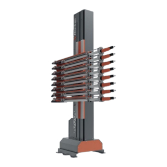
2. Function description 2.1. E-ROBOT+3 Z - Double Axis Reciprocator System E-ROBOT+3 Z is the general name of a system. It is not a single product, but a combination of several produ- cts. E-ROBOT+3 Z; E-ROBOT+3 Z E-DRIVE Z02-EX POWER & SIGNAL CABLES E-ROBOT+3 X NOTE: Each product is ordered separately in order to order a reciprocator system. -
Page 11: Special Characteristics
2.4. Special Characteristics The E-ROBOT+3 Z Reciprocator is conspicuous because of its rugged construction, a new drive system and an improved Z axis carriage design. Further characteristics: • 50 kg load capacity for automatic gun and gun holders • Quiet running •... -
Page 12: 3- Technical Data
3.Technical Data The E-ROBOT+3 Z Reciprocator is available, depending on operational area, in six versions with different standard stroke heights. 3.1.Technical Data *Vertical Axis 1200 E-ROBOT+3 Z 1500 1800 2100 2400 2700 2,524 m Height 2,824 m 3,124 m 3,424 m 3,724 m 4,024 m 1,2 m... -
Page 13: 4- Set-Up, Assembly And Commissioning
4.Set-up, assembly and commissioning WARNING: If a free-standing reciprocator is not anchored firmly to the floor, uncontrolled movement of the machine or insufficient stability can cause injuries. ** Firmly anchor the reciprocator to the floor if it is not mounted to another axis of motion. WARNING: The movement of the reciprocator can cause injuries. -
Page 14: 4-1.3 Connecting The E-Robot +3 X Horizontal Motion Unit To The Z Reciprocator
• Place Horızontal Unit Accordıng To The Project Values. Make sure the base is on a flat floor. Use M16 fixing plug. • Open bottom side covers of the reciprocator. • Position the reciprocator on the base of the horizontal unit. 4.1.3. - Page 15 Remove the back cover of the reciprocator (vertical axis). Route the cables through the cable holes (1) of the junction box mounted on the cover. (as shown in the picture) Connect the cable (according to the enclosed wiring diagram) NOTE: After positioning, the E-ROBOT+3 X Horizontal Motion Unit must be firmly fixed on the floor.
-
Page 16: 5- Commissioning
This is a factory setting. It will be set and sent. Unless necessary, do not pull by manually adjusting the move- ment mechanism of the horizontal axis. WARNING: In order to avoid damages to the booth or the gun holder etc. the reference point must be set by Electron authorized person before the first start-up! -
Page 17: Connections
5.2. Connections Electrical connections / cable connection First Reciprocator Second Reciprocator E-DRIVE ZX02-E Electrical connections of E-ROBOT+3 Z; Power supply cable (black) and signal cable (white) are connected between the E-DRIVE control unit and the control unit on the reciprocator. For each reciprocator to be added from now on, power and signal connections are made from the empty slots of the previous reciprocator with the same type of cables. -
Page 18: Reference Point And Mechanical Stops
It must be noted that the axes in reference travel moves up to 25 mm below the control’s zero point, therefore the mechanical stop must be set in accordance to the gun slots! The position of the upper and the lower stop plate is set by a Electron service engineer when the reciprocator is assembled. -
Page 19: Electrical Connections
Start up preferences After the power button on the back end of the control unit is turned on, pressing the power button on the front screen turns on the system. When there is an error in the Reciprocator, it writes the error code on the left side of the page and warns the operator. -
Page 20: 6-2.1 Basic Parameters
6.2.1. Basic Parameters In order for the robot to work properly, you should make the adjustments given in the table below in the motor driver located on the panel behind the robot. Here are the steps you need to follow to make the adjust- ments: 1)Press the ‘‘prog/data’’... -
Page 21: Axis Control Card Settings
6.3. Axis Control Card Settings WARNING: Do not apply this process while the robots have energy. Make sure that the jumper marked with a red ring is attached correctly. Depending on how many robots you have in your facility, the last one should be attached to pins 1 and 2. The last axis must be attached to pins 2 and 3. -
Page 22: Front Panel And Input Buttons
7.E-DRIVE ZX02-E Reciprocator Control Unit and Setting 7.1. Front Panel and Input Buttons Display No Display Name Main Switch (ON-OFF) Up Key Down Key Adjustment Led B5,B6,B7,B8,B9 Segment Buttons Rotary Adjustment Knob Reset Button Axis Start/Stop Button Menu Button Axes Active/Passive Button... -
Page 23: Start Up Preferences
7.2. Start up preferences After the power button on the back end of the control unit is turned on, pressing the power button on the front screen turns on the system. When there is an error in the Reciprocator, it writes the error code on the left side of the page and warns the operator. -
Page 24: 7-3.2 Axes Setup Page
Serial Communication: E-DRIVE ZX02-E controller unit has an optional connection to an automation system. In this case, the parameters of the control- ler can be controlled by any TCP/IP based automation system or by any other DRIVE ZX02-E device which is set as a “Master” in its network settings. -
Page 25: Main Menu Page
Code Info For Vertical Axis For Horizontal Axis Axis Type OSC. POS. Max POS. 1500/1800/2100/2400/2700/3000 1000 Min POS. HOM. Delay 50 ms HOM. Freq. 10 Hz 10 Hz Max Freq. 75 Hz 50 Hz Max V (Velocity) 36.0 m/min. 8.0 m/min. Min V 6.0 m/min. -
Page 26: Recipe Creation & Operating With Recipes
7.5. Recipe Creation & Operating with Recipes As mentioned in the above sections of this manual, E-DRIVE ZX02 can store up to recipes in memory. Operator can change the preferences of the reciprocator but changing the recipe is most of the time the easier thing to do. -
Page 27: Star T-Up Procedure 8-2 Error Codes
6.2. Error Codes Error Codes Explanation Solution - Check the connections of the sensor and whether it is defective. E0001 Home Position Error -Check the connections of the axis card and if it is defective - Control the stroke settings from the recipes through the interface. -
Page 28: 9- Maintenance
NOTE: All errors, except E220V, refer to the axis number which is indicated on the left side of the E-Drive control unit during operatinon. An Error Code, for instance, E1000 that has been observed during operating in axis page-2 does not mean that there is an E1000 error in all of the axises. - Page 29 **The installation takes place exactly in the reverse order! E-ROBOT+3 Z...
-
Page 30: Drive Belt
9.3.1 Replacing the drive unit WARNING: There is the risk of burns if contact is made with electrical components that have become overheated! **All work must be carried out only by technical personnel and when no power is applied! If it is necessary to replace a drive unit gearbox, the complete motor unit must be dismantled from the recipro- cator base. -
Page 31: 9-4.1.2 Belt Tension Settings
Belt Upper Locking Plate Belt Lower Locking Plate 9.4.1.2 Belt Tension Setting After the belt is installed, tighten the tension screws on the reciprocator to adjust its tension. You can adjust the belt tension according to the table below. NOTE: It is assumed that a force of F = 50 N is applied. -
Page 32: Drive Wheel
9.4.2 Replace the drive belt on the horizontal axis Procedure: 1.Switch off the electric power. 2.Remove all plates on the horizontal reciprocator. First loosen the tension screw on the tension plate (we do this so that the belt does not swing wit- hout control), then unscrew the tension plate (2 pcs) so that the drive belt can be pulled towards the locking plate. -
Page 33: Counterweight Plates
WARNING: Never loosen more than one roller at the same time! Adjust only one roller after another! 7. Adjust the roller pressure with the grub screw (3) , in such a way that the roller can just be turned by hand 8. -
Page 34: Reference Sensor
9.8. Reference Sensor WARNING: The following workings should only be carried out by trained personnel! 9.8.1 Replacing the zero point reference sensor on the vertical axis Procedure: 1. Let the Z carriage (7) move down onto the lower stop 2. Switch off the electric power 3. -
Page 35: Carriage
9.9. Incremental Pulse Generator (Encoder) WARNING: The following workings should only be carried out by trained personnel! Procedure: 1. Let the Z carriage (7) move down onto the lower stop 2. Switch off the electric power 3. Disconnect the encoder’s electrical connections from the connections shown on the schematic diagram. -
Page 36: Loading And Handing
10.Shipment, storage Reciprocator(s) is delivered on the desired date with a list of materials. All the materials are packaged accordingly for them to be fitted and fixed in the transport so that the risk of shipment damage is reduced. 10.1. Loading and Handling The following rules are important for handling: 1. -
Page 37: 11- Packing, Transpor T
10.3. Storage 1. All the goods have to be stored well until the installation. 2. For environmental protection, all goods have to be stored in the manner that has been sent. If there has to be more protection like extra lubrication, it has to be done in a similar manner. 10.3.1. - Page 38 C) Weight Stroke Lenght [mm] Reciprocator (kg) Case (kg) reciprocators with case-SET (kg) 1200 1500 1800 2100 2400 2700 Horizontal Reciprocator aprx. 250 (with palette) NOTE: Reciprocator enclosing dimensions are given so that two single vertical axes fit in the same case. 11.3.
- Page 39 2) For a single Reciprocator system; Systems Products Types Codes 1200 Stroke B07RG0301 1500 Stroke B07RG0302 1800 Stroke B07RG0303 E-ROBOT+3 Z 2100 Stroke B07RG0304 2400 Stroke B07RG0305 2700 Stroke B07RG0306 E-ROBOT+3 X 1000 Stroke / 1500 Stroke A05X031000 / A05X031500 E-DRIVE ZX02-E B08ZX02CM-E Double Axis...
-
Page 40: 12- Ordering
4) For dual Reciprocator systems; Systems Products Types Codes 1200 Stroke B07RG0301 1500 Stroke B07RG0302 1800 Stroke B07RG0303 E-ROBOT+3 Z 2100 Stroke B07RG0304 2400 Stroke B07RG0305 2700 Stroke B07RG0306 E-ROBOT+3 X 1000 Stroke / 1500 Stroke A05X031000 / A05X031500 E-DRIVE ZX02-E B08ZX02CM-E Double Axis Reciprocator... -
Page 41: Ordering Spare Parts
- Order number, quantity and description of each spare part WARNING: Only original ELECTRON spare parts should be used, because the explosion protection will also be preserved that way. The use of spare parts from other manufacturers will invalidate the Electron guarantee conditions! 12.2.1 E-ROBOT Z02-EX... - Page 42 Part # Order Code Part Name SIDE COVER OF THE RECIPROCATOR B06RB03121 E-ROBOT V3 1200 STROKE FRONT COVER B06RB03128 E-ROBOT V3 1500 STROKE FRONT COVER B06RB03133 E-ROBOT V3 1800 STROKE FRONT COVER B06RB03138 E-ROBOT V3 2100 STROKE FRONT COVER B06RB03143 E-ROBOT V3 2400 STROKE FRONT COVER B06RB03148 E-ROBOT V3 2700 STROKE FRONT COVER...
-
Page 43: 12-2.1 E-Robot+3 Z Ver Tical Axis Reciprocator - Spare Par Ts List
A-PART Part # Order Code Part Name AKUA08007 WHEEL Ø80 POLTAMID FIXED (YELLOW IRON) WHEEL PLATE FITTING WITH BRAKE Ø80 POLTAMID FIXED (YELLOW AKUA08003 IRON) B06RB03100 E-ROBOT V3 LOWER BASE B07RS0007 E-ROBOT+3 LOWER BASE FRONT - BACK COVER PLATE B06RB03098 E-ROBOT+3 LOWER BASE FRONT - BACK COVER PLATE B07RBM131 E-ROBOT VERTICAL AXIS RAIL-COMPLETE... - Page 44 Part # Order Code Part Name GAAE02005 TRIGGER GEAR BUSHING TYPE (Ø25 12.7 STEP ACCORDING TO SHAFT BUSHING PULLEY Ø25 GAAE06004 Part Name Order Code E-ROBOT+3 BOTTOM TENSION GEAR KIT B07RS0009 Part Name Order Code TRTM03104 E-ROBOT+3 BOTTOM BASE VARVEL REDUCER OUTPUT SHAFT...
- Page 45 B-PART 25.4 25.3 25.1 25.2...
- Page 46 Part # Order Code Part Name ELSN02008 SENSOR INDUCTIVE ATEX NBB8-18GM50-E2-3G-3D PEPPERL FUCHS B06RB01035 E-ROBOT SENSOR BASE B06RB03088 E-ROBOT V3 ROBOT SENSOR BASE COUNTERPART TRTM06005 E-ROBOT+3 STOPPER WEDGE BASE 25X20X128 TRTM06029 STOPPER WEDGE BASE LOWER PART Ø35X15 BECV06001 COATED BOLT M5X10 B06RB03085 E-ROBOT V3 BELT CONNECTION PLATE COUNTERPART B07RBM132...
- Page 47 Part Name Order Code E-ROBOT+3 Z CARRIAGE FRONT KIT B07RS0001 Part Name Order Code E-ROBOT+3 Z CARRIAGE BACK KIT B07RS0002...
- Page 48 C-PART Part # Order Code Part Name E-ROBOT V3 BELT CONNECTION PLATE B06RB03071 E-ROBOT+3 WELDED WEIGHT PLATE B06RB03073 COATED - GIJON M8 BEDH06002 COATED - NUT M8 BESM01006 ROBOT SMALL REEL Ø56 L25 TRTM08016 BEARING 6300 ZZ GAAE04019 DISTANCE BUSHING OF WEIGHT TROLLEY WHEEL Ø16 L23 TRTM06032 WEIGHT TROLLEY WHEEL OUTER BUSHING TRTM03082...
- Page 49 Part Name Order Code E-ROBOT+3 COUNTER CARRIAGE FRONT KIT B07RS0003 Part Name Order Code E-ROBOT+3 COUNTER CARRIAGE BACK KIT B07RS0004...
- Page 50 Part Name Order Code E-ROBOT+3 COUNTER WEIGHT FIXED SIDE PLATE B07RS0006...
- Page 51 D-PART Part # Order Code Part Name E-DRIVE RECIPROCATOR TOP GEAR SET - COMPLETE D-PART B07RBM130 INSTALLED TRACTION GEAR GAAE02006 TOP GEAR TRACTION PART TRTM06009 TOP GEAR TRACTION LOCK PART B06RB01034 WELDED TOP GEAR TRACTION SET B07RS0005 M12X75 EYEBOLT PASO DIN444 BECV06162 TOP GEAR TRACTION SCREW GAAE04019...
- Page 52 Part Name Order Code E-ROBOT+3 TOP TENSION GEAR SET B07RS0008...
-
Page 53: 12-2.2 E-Robot+3 X Horizontal Axis Reciprocator - Spare Parts List
E-PART Part # Order Code Part Name E-DRIVE ZX02-E ROBOT MECHANICAL UNIT ELECTRICAL PANEL B08ZX02CP-E HINGE 299-1-2-1 AKUA01002 LOCK 140-1-2-64-01 ELPA04003 SOCKET BINDER SOLDERED TYPE 7 PIN FEMALE PANEL CONNEC- ELKS03003 SOCKET BINDER SCREW TYPE 4 PIN MALE PANEL TYPE CONNEC- ELKS03006 CABLE ENTRY PART ELKA15002... - Page 54 F-PART Part Part # Order Code Name Ø30 CLAMP FOR E-GUN C3 (AUTO. GUN) B07EH50908 Ø40x30 CLAMP B07EH50906 Ø40xOVAL CLAMP B07EH50905 Ø40x40 CLAMP B07EH50904 ROBOT BODY Ø40 CLAMP B07EH50907 COMPOSITE TYPE RECIPROCATOR ARM - COM- B07RCA001 PLETE Ø30x3 ALUMINIUM PIPE SCBR03004 Ø40x5 ALUMINIUM PIPE SCBR03005...
- Page 55 12.2.2 E-ROBOT+3 X Horizontal Axis Reciprocator - Spare Parts List Part # Order Code Part Name E-DRIVE RECIPROCATOR HORIZONTAL AXIS FRAME B07RBM133 SHOCK OBSERVER M8X27 30X36 K-TYPE AKUA03020 E-ROBOT HORIZONTIAL AXIS MOTION PLATE B06RB02018 E-ROBOT HORIZONTIAL AXIS TOP COVER-2 B06RB02020 E-ROBOT HORIZONTIAL AXIS TOP COVER-1 B06RB02019 TRIGER BELT H100 BLACK-ANTISTATIC (12,7 STEP)
- Page 56 A-PART A2-Part Part Part # Order Code Name B06RB02004 E-ROBOT HORIZONTAL AXIS / REDUCER BOX E-DRIVE RECIPROCATOR HORIZONTAL AXIS/ DUCTED B07RBM135 WHEEL BASE-LEFT-COMPLETE E-DRIVE RECIPROCATOR HORIZONTAL AXIS/ DUCTED B07RBM136 WHEEL BASE - RIGHT - COMPLETE E-DRIVE RECIPROCATOR HORIZONTAL AXIS/ WHEEL B07RBM134 BASE - LEFT - COMPLETE E-DRIVE RECIPROCATOR HORIZONTAL AXIS/ WHEEL...
- Page 57 A2-PART Part Part # Order Code Name TRIGER GEAR Z = 22 BUSH TYPE (12.7 STEP BY Ø18 GAAE02007 SHAFT) ENCODER ROTARY ATEX ZONE 22 B07500600 TRTM06034 ROBOT - EX ENCODER CONNECTING SHAFT E-ROBOT+3 Horizontal Axis Gearbox Front Flange B06RB03041 E-ROBOT+3 HORIZONTAL AXIS ATEX ENCODER TRTM03080 CONNECTING SHAFT...
-
Page 58: 12-2.3 E-Drive Zx02-Ex Reciprocator Control Unit- Spare Parts List
B-PART Part # Order Code Part Name B06RB02003 E-ROBOT HORIZONTAL AXIS TRIGER BELT FIXING PLATE B06RB02016 E-ROBOT HORIZONTAL AXIS FIXED SIDE TRIGER LOCK BECV06014 BOLT M8X25 PLATED BEPL04005 M8 SPRING RONDELA PLATED BESM01006 BOLT M8 PLATED... - Page 59 C-PART Part Part # Order Code Name TRTM06007 TRIGER STRETCHING TOP LOCK PROVISION 30X40X80 TRTM06028 TENSION UPPER LOCK 40X90X20 BEDH06003 M10 GIJON PLATED-0.10 M BEDH06003 M10 GIJON PLATED-0.12 M B06RB02015 E-ROBOT HORIZONTAL AXIS TENSION SIDE TRIGER LOCK BECV06007 BOLT M6X35 PLATED BESM01005 NUT M6 PLATED BESM01011...
- Page 60 12.2.3 E-DRIVE ZX02- EX Reciprocator Control Unit - Spare Parts List Part # Order Code Part Name B07EC5001 E-COAT UNIT CASE ENEM02001 E-COAT CONTROL UNIT FRAME IZCS01004 E-COAT FRONT/BACK SEALING B07EC5003 E-COAT MASTER FRONT ALUMINUM SHEET ELON09021 E-DRIVE-E ROBOT MODULE MAINBOARD ELON09022 E-DRIVE-E ROBOT MODULE I/O CARD ELBS01001...
- Page 61 Part # Order Code Part Name ELSL07012 MAIN AND EMERGENCY ON/OFF SWITCH 2X25A ELKS03001 SOCKET RD24-SCREW TYPE 4 PIN FEMALE PANEL CONNECTOR ELKS03003 SOCKET RD24-SOLDERED TYPE 7 PIN FEMALE PANEL CONNECTOR ELKS09002 SOCKET RJ 45 ETHERNET PANEL TYPE ELKS03010 SOCKET RD24-SOLDERED TYPE 7 PIN MALE PANEL CONNECTOR ELDE06006 FUSE HOLDER SHURTER IP67 5X20A 16.1...
-
Page 62: Electrical Schematic Diagram
13. Electrical Schematic Diagram 13.1 Electrical Scheme of E- Drive ZXO2-E Reciprocator Control Unit... -
Page 63: Electrical Scheme Of E-Robot+3 Z Mechanical Unit Panel
13.2 Electrical Scheme of E- Robot+3 Z Mechanical Unit Panel... - Page 64 Grounding Diagram WARNING: Missing or incorrect grounding A bad or missing ground connection can be dangerous to the operator. • Ground all metal parts of the axis according to the general, local safety regulations. • Check regularly the grounding of the axis. Part # Order Code Part Name...
-
Page 65: Fault Chart
Fault Chart Error Solution Loosen the motor and move it manually into the appropriate The toothed belt rides up opposite direction. on the flanged wheel The toothed belt may not ride up on the flanged wheel at the whole driveway as well as in the reversal points. Check the connecting bolts between reciprocator, carriage plate and the E-ROBOT+3 Z Horizontal Motion Unit car- riage for tightness. -
Page 66: 14- Groung Diagram 15- 16- Service Chart
16.SERVICE AND MAINTENANCE CHART MAINTENANCE TYPE PROCEDURE -Weekly maintenance MAINTENANCE OR AUTHORIZED DATE REPLACEMENT PARTS -Yearly maintenance SERVICE PERSONNEL CONTROLLER NOTES -Service... -
Page 67: 17- Product Life And Warranty
17. Product Life and Warranty 17.1. Product Life • The economic life of E-DRIVE ZX02-E Z-Axis Reciprocator is approximately 10 years. • This product life is highly dependent on the periodic maintenances and spare part changes in a timely manner. Improper maintenance will lead to lower product life. •... - Page 68 PERPA Tic. Mer. B-Blok Kat:2 No:65 İTOB Org. San. Bölgesi 10010 Sk. No:10 34385, Okmeydanı – İSTANBUL/TÜRKİYE 35470, Menderes – İZMİR/TÜRKİYE Telefon: +90 (212) 222 23 45 Telefon: +90 (232) 799 02 32 Mail: info@electron.com.tr Fax: +90 (232) 799 02 42...
Need help?
Do you have a question about the E-ROBOT+3 Series and is the answer not in the manual?
Questions and answers