
Related Manuals for Siemens SIMATIC NET RUGGEDCOM RST916P


Summary of Contents for Siemens SIMATIC NET RUGGEDCOM RST916P
- Page 1 Edition 11/2023 Equipment Manual SIMATIC NET Rugged Ethernet switches RUGGEDCOM RST916P https://www.siemens.com/ruggedcom...
- Page 2 Preface Introduction Installing the Device SIMATIC NET Device Management Rugged Ethernet switches RUGGEDCOM RST916P Communication Ports Technical Specifications Equipment Manual Certification 11/2023 C79000-G8976-1489-06...
- Page 3 Note the following: WARNING Siemens products may only be used for the applications described in the catalog and in the relevant technical documentation. If products and components from other manufacturers are used, these must be recommended or approved by Siemens. Proper transport, storage, installation, assembly, commissioning, operation and maintenance are required to ensure that the products operate safely and without any problems.
-
Page 4: Table Of Contents
SIMATIC NET glossary ......................vi Registered trademarks ......................vi Warranty ..........................vii Training ..........................vii Customer support ......................... viii Contacting Siemens ......................viii Introduction ........................... 1 Feature Highlights ....................2 Description ......................2 Required Tools and Materials ................. 4 Decommissioning and disposal ................4 Installing the Device ...................... - Page 5 Table of contents General specifications ..................29 Power Supply Specifications ................29 PoE Output Specifications ..................29 Failsafe Alarm Relay Specifications ..............30 Supported Networking Standards ................ 30 Copper Ethernet Port Specifications ..............31 Operating Environment ..................31 Mechanical Specifications ..................31 Dimension Drawings ...................
-
Page 6: Preface
Siemens' products and solutions undergo continuous development to make them more secure. Siemens strongly recommends that product updates are applied as soon as they are available and that the latest product versions are used. Use of product versions that are no longer supported, and failure to apply the latest updates may increase customer's exposure to cyber threats. -
Page 7: Supplementary Documentation
SIMATIC NET glossary The SIMATIC NET glossary describes special terms that may be used in this document. The glossary is available online via Siemens Industry Online Support (SIOS) at: https://support.industry.siemens.com/cs/ww/en/view/50305045 Registered trademarks The following and possibly other names not identified by the registered trademark sign ®... -
Page 8: Warranty
Warranty Siemens warrants this product for a period of five (5) years from the date of purchase, conditional upon the return to factory for maintenance during the warranty term. This product contains no user-serviceable parts. Attempted service by unauthorized personnel shall render all warranties null and void. -
Page 9: Customer Support
Call a local hotline center to submit a Support Request (SR). To locate a local hotline center, visit https://w3.siemens.com/aspa_app/?lang=en. Mobile app Install the Industry Online Support app by Siemens AG on any Android, Apple iOS or Windows mobile device and be able to: •... -
Page 10: Introduction
Introduction The RUGGEDCOM RST916P is a 16-port utility-grade, fully managed Ethernet switch specifically designed to operate reliably in electrically harsh and climatically demanding environments. • Removable SFP Transceivers The device supports up to four Small Form-factor Portable (SFP) transceivers, allowing the device to be adapted to the requirements of the network application. -
Page 11: Feature Highlights
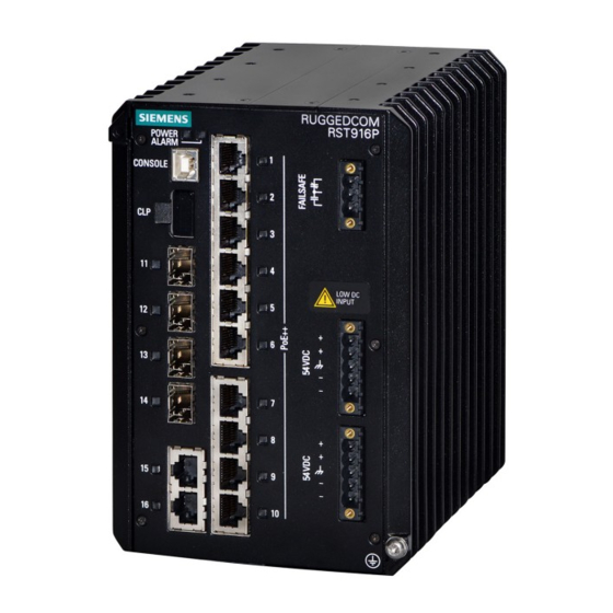
Introduction 1.1 Feature Highlights Feature Highlights Ethernet Ports • 4 x sockets for SFP/SFP+ transceivers • 2 x 10/100/1000Base-T copper Ethernet ports • 10 x 10/100/1000Base-T RJ45 802.3af//802.3at/802.3bt compliant Power-over- Ethernet (PoE) ports • Data and power over a single PoE cable •... - Page 12 Introduction 1.2 Description POWER LED ALARM LED USB Console Port CLP Port SFP Tranceiver Sockets (Ports 11 to 14) Copper Ethernet Ports (Ports 15 and 16) Failsafe Alarm Relay Copper PoE Ports (Ports 1 to 10) Power Supply Terminal Block Chassis Ground Screw Figure 1.1 RUGGEDCOM RST916P POWER LED...
-
Page 13: Required Tools And Materials
WEEE directive 2012/19/EU for the disposal of electrical and electronic equipment. Do not dispose of devices at public disposal sites. For environmentally friendly recycling and the disposal of devices, contact a certified disposal company for electronic scrap or your Siemens contact. RUGGEDCOM RST916P Equipment Manual, 11/2023, C79000-G8976-1489-06... - Page 14 Introduction 1.4 Decommissioning and disposal For more information, refer to https://support.industry.siemens.com/cs/ww/en/ view/109479891. Note the different national regulations. RUGGEDCOM RST916P Equipment Manual, 11/2023, C79000-G8976-1489-06...
- Page 15 Introduction 1.4 Decommissioning and disposal RUGGEDCOM RST916P Equipment Manual, 11/2023, C79000-G8976-1489-06...
-
Page 16: Installing The Device
Installing the Device This chapter describes how to install the device, including mounting the device, connecting power, and connecting the device to the network. DANGER Electrocution hazard – risk of serious personal injury and/or damage to equipment Before performing any maintenance tasks, make sure all power to the device has been disconnected and wait approximately two minutes for any remaining energy to dissipate. -
Page 17: General Procedure
This product contains no user-serviceable parts. Attempted service by unauthorized personnel shall render all warranties null and void. Changes or modifications not expressly approved by Siemens Canada Ltd. could invalidate specifications, test results, and agency approvals, and void the user's authority to operate the equipment. -
Page 18: Unpacking The Device
Visually inspect each item in the package for any physical damage. Verify all items are included. Note If any item is missing or damaged, contact Siemens for assistance. Mounting the Device The RUGGEDCOM RST916P is designed for maximum mounting and display flexibility. - Page 19 Installing the Device 2.3.1 Mounting the Device on a DIN Rail DIN Rail DIN Rail Adapter Figure 2.1 Mounting the Device to a DIN Rail Insert a flathead screwdriver into the slot of the sliding release and move it down. Push the device against the bottom of the DIN rail, then let go of the sliding release to latch the device.
-
Page 20: 2.3.2 Mounting The Device To A Panel
Installing the Device 2.3.2 Mounting the Device to a Panel DIN Rail DIN Rail Adapter Figure 2.2 Removing the Device from a DIN Rail Swing the bottom of the device away from the DIN rail. Lift the device off the DIN rail. 2.3.2 Mounting the Device to a Panel For panel installations, the RUGGEDCOM RST916P can be equipped with panel... - Page 21 Installing the Device 2.3.2 Mounting the Device to a Panel Side-Mount Orientation Figure 2.3 Panel Mount Options To mount the device to a panel, do the following: Secure the mounting adapters to the top and bottom of the device in the desired orientation using the eight M4 screws included with the device.
-
Page 22: Connecting The Failsafe Alarm Relay
Installing the Device 2.4 Connecting the Failsafe Alarm Relay Screw (M5 or #10-24) Panel Mount Adapter Figure 2.5 Panel Mounting (Rear Mount Orientation) Secure the adapters to the panel with screws. Connecting the Failsafe Alarm Relay The failsafe relay can be configured to latch based on alarm conditions. The NO (Normally Open) contact is closed when the unit is powered and there are no active alarms. - Page 23 Installing the Device 2.4 Connecting the Failsafe Alarm Relay Figure 2.6 Assembling the Failsafe Alarm Relay Terminal Block Connect a failsafe device to the terminal block. Failsafe Alarm Relay Terminal Block Normally Open Common Normally Closed Figure 2.7 Failsafe Alarm Relay Wiring RUGGEDCOM RST916P Equipment Manual, 11/2023, C79000-G8976-1489-06...
-
Page 24: Connecting Power
Installing the Device 2.5 Connecting Power Connecting Power The RUGGEDCOM RST916P features two input terminals that allow the device to be powered by two independent DC power sources. Each power source must provide 54 VDC nominal output voltage. Note The RUGGEDCOM RST916P is a dual input power supply system. Due to this structure, induced voltages will be observed between the positive and chassis/ground terminals, and between the negative and chassis/ground terminals. -
Page 25: 2.5.2 Connecting Dc Power
For IEC 61850 compliance, use an IEC 61850 compliant PoE power supply with power cabling no longer than 3 m (118 in). Otherwise, Siemens recommends using the RUGGEDCOM RPS1300 switch-mode AC power supply. For more information about this power supply, refer to https:// support.industry.siemens.com/cs/ww/en/view/109478699. - Page 26 Installing the Device 2.5.2 Connecting DC Power Figure 2.8 Assembling the Power Terminal Blocks Note Torque all terminal connections to 0.6 N·m (5 lbf-in). Note Each positive (+) terminal is identical, as are the negative (-) terminals. Cables from an external power supply can be connected to any of the corresponding terminals on the same terminal block.
-
Page 27: 2.5.3 Wiring Examples
Installing the Device 2.5.3 Wiring Examples M4 Screw M4 Ring Tongue Figure 2.9 Chassis Ground Connection Connect the external power supply to a power source. The Power LED on the device will turn green when the device has booted up, indicating power is being supplied to the device. - Page 28 Installing the Device 2.5.3 Wiring Examples Figure 2.12 Single DC Power Input Figure 2.13 Dual DC Power Input Configuration with Dual Configuration with Dual Positive/Negative Inputs Positive/Negative Inputs RUGGEDCOM RST916P Equipment Manual, 11/2023, C79000-G8976-1489-06...
- Page 29 Installing the Device 2.5.3 Wiring Examples RUGGEDCOM RST916P Equipment Manual, 11/2023, C79000-G8976-1489-06...
-
Page 30: Device Management
Device Management This section describes how to connect to and manage the device. Connecting to the Device The following describes the various methods for accessing the RUGGEDCOM RST916P console and Web interfaces on the device. For more detailed instructions, refer to the "RUGGEDCOM ROS Configuration Manual"... -
Page 31: Configuring The Device
Device Management 3.2 Configuring the Device device's IP address. The factory default IP address for the RUGGEDCOM RST916P is https://192.168.0.1. For more information about available ports, refer to "Communication Ports" (Page 25). Configuring the Device Once the device is installed and connected to the network, it must be configured. All configuration management is done via the RUGGEDCOM RST916P interface. - Page 32 Device Management 3.3 Inserting/Removing the CLP Removing the CLP To remove the CLP, do the following: NOTICE Configuration hazard – risk of data loss After uploading or downloading a file, allow at least twenty seconds before removing the CLP to ensure the data has been fully transferred. Remove the CLP (or blank insert) from the CLP port.
- Page 33 Device Management 3.3 Inserting/Removing the CLP Blank Insert Figure 3.2 Inserting the CLP Insert the CLP into the CLP port. RUGGEDCOM RST916P Equipment Manual, 11/2023, C79000-G8976-1489-06...
-
Page 34: Communication Ports
Communication Ports The RUGGEDCOM RST916P can be equipped with various types of communication ports to enhance its abilities and performance. Ports 1 to 10 Ports 11 to 14 Ports 15 to 16 Figure 4.1 Port Assignment Port Type 1 to 10 Copper (10/100/1000Base-T) Power-over-Ethernet (PoE) Ports 11 to 14 SFP/SFP+ Transceivers... -
Page 35: Copper Ethernet Ports
Communication Ports 4.1 Copper Ethernet Ports Copper Ethernet Ports The device supports multiple 10/100/1000Base-TX Ethernet ports that allow connection to standard Category 5E (CAT-5E) or higher shielded twisted-pair cables with RJ45 male connectors. WARNING Electric shock hazard – risk of serious personal injury and/or equipment interference When shielded cables are used, make sure the shielded cables do not form a ground loop via the shield wire and the RJ45 receptacles at either end. -
Page 36: Poe Ports
Communication Ports 4.2 PoE Ports Name Description 10/100Base-TX 1000Base-TX Reserved (Do Not Connect) BI_DC- Bi-Directional Specifications For specifications on the available copper Ethernet ports, refer to "Copper Ethernet Port Specifications" (Page 31). PoE Ports The RUGGEDCOM RST916P features Power-over-Ethernet (PoE) ports (ports 1 to 10) powered by an external power supply. -
Page 37: Sfp Transceivers
"RUGGEDCOM SFP Transceiver Catalog [https:// support.industry.siemens.com/cs/ca/en/view/109482309]". Note Only use SFP transceivers approved by Siemens for RUGGEDCOM products. Siemens accepts no liability as a result of performance issues related in whole or in part to third-party components. RUGGEDCOM RST916P... -
Page 38: Technical Specifications
Technical Specifications This section provides important technical specifications related to the device. General specifications Insulation Class I Overvoltage category OVC II Power Supply Specifications Note When determining cable lengths, make sure the nominal input voltage for the power supply is provided at the power source. Power Minimum Maximum... -
Page 39: Failsafe Alarm Relay Specifications
Technical Specifications 5.4 Failsafe Alarm Relay Specifications Failsafe Alarm Relay Specifications Maximum Switching Voltage Rated Isolation Switching Current 30 VDC 5.0 kVAC between coil and contacts 125 VDC 0.48 A 1.0 kVAC between contacts 300 VDC 0.2 A 250 VAC 50 to 60 Hz for 1 minute Supported Networking Standards The following networking standards are supported by RUGGEDCOM RST916P: Standard... -
Page 40: Copper Ethernet Port Specifications
Technical Specifications 5.6 Copper Ethernet Port Specifications Copper Ethernet Port Specifications The following details the specifications for copper Ethernet ports that can be ordered with the RUGGEDCOM RST916P. Speed 10/100/1000Base-TX Connector RJ45 Duplex FDX/HDX Cable Type CAT 5E or higher Wiring Standard TIA/EIA T568A/B Maximum Distance 100 m (328 ft) -
Page 41: Dimension Drawings
Technical Specifications 5.9 Dimension Drawings Dimension Drawings Note All dimensions are in millimeters, unless otherwise stated. 116.1 164.5 Figure 5.1 Overall Dimensions 116.1 78.6 60.0 165.3 Figure 5.2 Panel Mount Dimensions (Rear Mount Orientation) RUGGEDCOM RST916P Equipment Manual, 11/2023, C79000-G8976-1489-06... - Page 42 Technical Specifications 5.9 Dimension Drawings 125.1 107.9 55.0 69.3 16.3 60.0 132.5 Figure 5.3 Panel Mount Dimensions (Side Mount Orientation) RUGGEDCOM RST916P Equipment Manual, 11/2023, C79000-G8976-1489-06...
- Page 43 Technical Specifications 5.9 Dimension Drawings RUGGEDCOM RST916P Equipment Manual, 11/2023, C79000-G8976-1489-06...
-
Page 44: Certification
Assessed (UKCA) marking. The marking is printed on the body of the device. 6.1.2 European Union (EU) This device is declared by Siemens Canada Ltd. to comply with essential requirements and other relevant provisions of the following EU directives: •... -
Page 45: 6.1.3 Fcc
Title 21 Code of Federal Regulations (CFR) – Chapter I – Sub-chapter J – Radiological Health 6.1.5 ISED This device is declared by Siemens Canada Ltd. to meet the requirements of the following ISED (Innovation Science and Economic Development Canada) standard: • CAN ICES-3 (A)/NMB-3 (A) -
Page 46: Tüv Süd
Republic of Korea (South Korea) as a Class A product in a commercial, industrial or business environment. R-R-S14-RST916P A copy of the KC Declaration of Conformity is available from Siemens Canada Ltd.. For contact information, refer to "Contacting Siemens" (Page viii). Notices specific to the RRA:... -
Page 47: 6.1.9 Rohs
Certification 6.1.9 RoHS 6.1.9 RoHS This device is declared by Siemens Canada Ltd. to meet the requirements of the following RoHS (Restriction of Hazardous Substances) directives for the restricted use of certain hazardous substances in electrical and electronic equipment: • EU RoHS Directives (EU) 2011/65 and (EU) 2015/863 European Directive for Restriction of Hazardous Substances •... - Page 48 Certification 6.2 EMC and Environmental Type Tests EMC Type Tests Test Description Test Levels Severity Levels Enclosure ± 8 kV 61000-4-2 Contact Enclosure Air ± 15 kV Radiated RFI Enclosure 20 V/m 61000-4-3 Ports Burst (Fast Transient) Signal Ports ± 4 kV @ 2.5 kHz, 5 kHz 61000-4-4 DC Power ±...
- Page 49 Certification 6.2 EMC and Environmental Type Tests Test Description Test Levels Severity Levels 100% for 0.05 s Dielectric Strength Signal Ports 2 kV (Failsafe Relay Output) 60255-27 DC Power 2 kV or 2.8kV DC Ports AC Power 2 kV ...
- Page 50 Certification 6.2 EMC and Environmental Type Tests Environmental Type Tests Test Description Test Levels Severity Levels IEC 60068-2-1 Cold Temperature Test Ad -40 °C (-40 °F), 16 Hours Cold Storage Test Ab -40 °C (-40 °F), 16 Hours IEC 60068-2-2 Dry Heat Test Bd 85 °C (185...
- Page 51 Certification 6.2 EMC and Environmental Type Tests RUGGEDCOM RST916P Equipment Manual, 11/2023, C79000-G8976-1489-06...
- Page 52 For more information Siemens RUGGEDCOM https://www.siemens.com/ruggedcom Industry Online Support (service and support) https://support.industry.siemens.com Industry Mall https://mall.industry.siemens.com Siemens Canada Ltd. Digital Industries Process Automation 300 Applewood Crescent Concord, Ontario, L4K 4E5 Canada © 2023 Siemens Canada Ltd. Subject to change...
Need help?
Do you have a question about the SIMATIC NET RUGGEDCOM RST916P and is the answer not in the manual?
Questions and answers