
Related Manuals for Siemens SIMATIC NET RUGGEDCOM RST916C


Summary of Contents for Siemens SIMATIC NET RUGGEDCOM RST916C
- Page 1 Installation Manual SIMATIC NET Rugged Ethernet Switches RUGGEDCOM RST916C Edition 04/2021 https://www.siemens.com...
- Page 2 Preface Introduction Installing the Device SIMATIC NET Device Management Rugged Ethernet Switches RUGGEDCOM RST916C Communication Ports Technical Specifications Installation Manual Certification 04/2021 C79000-G8976-1490-03...
- Page 3 Note the following: WARNING Siemens products may only be used for the applications described in the catalog and in the relevant technical documentation. If products and components from other manufacturers are used, these must be recommended or approved by Siemens. Proper transport, storage, installation, assembly, commissioning, operation and maintenance are required to ensure that the products operate safely and without any problems.
-
Page 4: Table Of Contents
Accessing Documentation ....................... v Registered Trademarks ......................v Warranty ..........................v Training ..........................vi Customer Support ........................vi Contacting Siemens ....................... vii Introduction ........................... 1 Feature Highlights ....................2 Description ......................2 Required Tools and Materials ................. 4 Decommissioning and Disposal ................4 Installing the Device ...................... - Page 5 Table of Contents Supported Networking Standards ................ 28 Copper Ethernet Port Specifications ..............29 Operating Environment ..................29 Mechanical Specifications ..................30 Dimension Drawings ................... 30 Certification ......................... 33 Approvals ......................33 6.1.1 CSA ........................33 6.1.2 CSANe ......................... 34 6.1.3 FCC ........................
-
Page 6: Preface
Warranty Siemens warrants this product for a period of five (5) years from the date of purchase, conditional upon the return to factory for maintenance during the warranty term. This product contains no user-serviceable parts. Attempted service by unauthorized personnel shall render all warranties null and void. -
Page 7: Training
Siemens Sales representative. Customer Support Customer support is available 24 hours, 7 days a week for all Siemens customers. For technical support or general information, contact Siemens Customer Support through any of the following methods: Online Visit http://www.siemens.com/automation/support-request... -
Page 8: Contacting Siemens
Contacting Siemens • Submit SRs or check on the status of an existing SR • Contact a local Siemens representative from Sales, Technical Support, Training, etc. • Ask questions or share knowledge with fellow Siemens customers and the support community... - Page 9 Preface Contacting Siemens viii RUGGEDCOM RST916C Installation Manual, 04/2021, C79000-G8976-1490-03...
-
Page 10: Introduction
Introduction The RUGGEDCOM RST916C is a 16-port utility-grade, fully managed Ethernet switch specifically designed to operate reliably in electrically harsh and climatically demanding environments. • Removable SFP Transceivers The device supports up to four Small Form-factor Portable (SFP) transceivers, allowing the device to be adapted to the requirements of the network application. -
Page 11: Feature Highlights
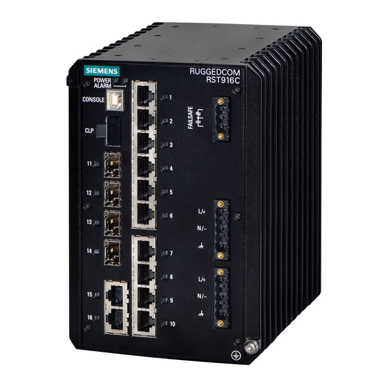
Introduction 1.1 Feature Highlights • RUGGEDCOM ROS RUGGEDCOM ROS provides advanced Layer 2 networking functions and cyber security features. Feature Highlights Ethernet Ports • 4 x sockets for SFP/SFP+ transceivers • 12 x 10/100/1000Base-T copper Ethernet ports Rated for Reliability in Harsh Environments •... - Page 12 Introduction 1.2 Description LO DC Variant HI AC/DC Variant POWER LED ALARM LED USB Console Port CLP Port SFP Tranceiver Sockets (Ports 11 to 14) Copper Ethernet Ports (Ports 1 to 10, 15, and 16) Failsafe Alarm Relay Power Supply Terminal Block Chassis Ground Screw Figure 1.1 RUGGEDCOM RST916C...
-
Page 13: Required Tools And Materials
Introduction 1.3 Required Tools and Materials Power Supply Terminal Blocks Pluggable terminal blocks for connecting one or more power sources. For more information, refer to "Connecting Power (Page 14)" "Power Supply Specifications (Page 27)". Chassis Ground Terminal Protects the device from power surges and accumulated static electricity. -
Page 14: Installing The Device
This product contains no user-serviceable parts. Attempted service by unauthorized personnel shall render all warranties null and void. Changes or modifications not expressly approved by Siemens AG could invalidate specifications, test results, and agency approvals, and void the user's authority to operate the equipment. -
Page 15: General Procedure
Inspect the package for damage before opening it. Visually inspect each item in the package for any physical damage. Verify all items are included. Note If any item is missing or damaged, contact Siemens for assistance. RUGGEDCOM RST916C Installation Manual, 04/2021, C79000-G8976-1490-03... -
Page 16: Installing The Device In Hazardous Locations
Installing the Device 2.3 Installing the Device in Hazardous Locations Installing the Device in Hazardous Locations The RUGGEDCOM RST916C is designed to comply with the safety standards for Class I, Division 2, Zone 2 hazardous locations where concentrations of flammable gases, vapors or liquids may be present, as opposed to normal operating environments. -
Page 17: Mounting The Device
Installing the Device 2.4 Mounting the Device Sample Hazardous Location Label The following is an example of the RUGGEDCOM RST916C hazardous location label: II 3 G Figure 2.1 Compliance Label (Example) Mounting the Device The RUGGEDCOM RST916C is designed for maximum mounting and display flexibility. - Page 18 Installing the Device 2.4.1 Mounting the Device on a DIN Rail Mounting the Device To mount the device to a DIN rail, do the following: Hook the top teeth of the adapter onto the DIN rail. Note The adapter features a sliding release with a slot at the bottom for a flathead screwdriver.
-
Page 19: 2.4.2 Mounting The Device To A Panel
Installing the Device 2.4.2 Mounting the Device to a Panel Removing the Device To remove the device from a DIN rail, do the following: Insert a flathead screwdriver into the slot of the sliding release and move it down. DIN Rail DIN Rail Adapter Figure 2.3 Removing the Device from a DIN Rail... - Page 20 Installing the Device 2.4.2 Mounting the Device to a Panel Rear-Mount Orientation Side-Mount Orientation Figure 2.4 Panel Mount Options To mount the device to a panel, do the following: Secure the mounting adapters to the top and bottom of the device in the desired orientation using the eight M4 screws included with the device.
-
Page 21: Connecting The Failsafe Alarm Relay
Installing the Device 2.5 Connecting the Failsafe Alarm Relay Place the device against the panel and align the adapters with the mounting holes. Screw (M5 or #10-24) Panel Mount Adapter Figure 2.6 Panel Mounting (Rear Mount Orientation) Secure the adapters to the panel with screws. Connecting the Failsafe Alarm Relay The failsafe relay can be configured to latch based on alarm conditions. - Page 22 Installing the Device 2.5 Connecting the Failsafe Alarm Relay To connect the failsafe alarm relay, do the following: Insert the failsafe alarm relay terminal block into the device and tighten the screws. Figure 2.7 Assembling the Failsafe Alarm Relay Terminal Block Connect a failsafe device to the terminal block. Failsafe Alarm Relay Terminal Block Normally Open Common...
-
Page 23: Connecting Power
Installing the Device 2.6 Connecting Power Connecting Power The RUGGEDCOM RST916C features two input terminals that allow the device to be powered by: • Up to one independent AC and one independent DC power source • Two independent DC power sources NOTICE Electrical hazard –... - Page 24 Installing the Device 2.6.1 Connecting AC or DC Power WARNING Electrocution hazard – risk of personal injury When only one AC power source is connected to the device, the redundant power terminals (between the positive/live and chassis/ground terminals, and between the neutral and chassis/ground terminals) are energized.
- Page 25 Installing the Device 2.6.1 Connecting AC or DC Power Connect the power cable to the device as follows: HI AC/DC Power Supply Connect the Line wire (AC) or Positive wire (DC) to the positive/ live (+/L) terminal on the terminal block.
-
Page 26: 2.6.2 Wiring Examples
Installing the Device 2.6.2 Wiring Examples 2.6.2 Wiring Examples The following illustrate how to connect single and dual power supplies to the device. HI Power Supply Configurations Figure 2.13 Single HI AC Power Input Figure 2.14 Single HI DC Power Input Configuration Configuration ... - Page 27 Installing the Device 2.6.2 Wiring Examples LO Power Supply Configurations Figure 2.17 Single LO DC Power Input Figure 2.18 Dual LO DC Power Input Configuration Configuration RUGGEDCOM RST916C Installation Manual, 04/2021, C79000-G8976-1490-03...
-
Page 28: Device Management
Device Management This section describes how to connect to and manage the device. Connecting to the Device The following describes the various methods for accessing the RUGGEDCOM RST916C console and Web interfaces on the device. For more detailed instructions, refer to the RUGGEDCOM ROS Configuration Manual for the RUGGEDCOM RST916C. Note Ethernet cables should be only be connected/disconnected in a non-hazardous area, or when the device is not energized. -
Page 29: Configuring The Device
Device Management 3.2 Configuring the Device Ethernet Ports Connect any of the available Ethernet ports on the device to a management switch and access the RUGGEDCOM RST916C console and Web interfaces via the device's IP address. The factory default IP address for the RUGGEDCOM RST916C is https://192.168.0.1. - Page 30 Device Management 3.3 Inserting/Removing the CLP Removing the CLP To remove the CLP, do the following: NOTICE Configuration hazard – risk of data loss After uploading or downloading a file, allow at least twenty seconds before removing the CLP to ensure the data has been fully transferred. Remove the CLP (or blank insert) from the CLP port.
- Page 31 Device Management 3.3 Inserting/Removing the CLP Inserting the CLP To insert the CLP, do the following: Remove the current CLP (or blank insert) from the device. Blank Insert Figure 3.2 Inserting the CLP Insert the CLP into the CLP port. RUGGEDCOM RST916C Installation Manual, 04/2021, C79000-G8976-1490-03...
-
Page 32: Communication Ports
Communication Ports The RUGGEDCOM RST916C can be equipped with various types of communication ports to enhance its abilities and performance. Ports 1 to 10 Ports 11 to 14 Ports 15 to 16 Figure 4.1 Port Assignment Port Type 1 to 10 Copper (10/100/1000Base-T) Ethernet Ports 11 to 14 SFP/SFP+ Transceivers... -
Page 33: Copper Ethernet Ports
Communication Ports 4.1 Copper Ethernet Ports Copper Ethernet Ports The device supports multiple 10/100/1000Base-TX Ethernet ports that allow connection to standard Category 5E (CAT-5E) or higher shielded twisted-pair cables with RJ45 male connectors. WARNING Electric shock hazard – risk of serious personal injury and/or equipment interference When shielded cables are used, make sure the shielded cables do not form a ground loop via the shield wire and the RJ45 receptacles at either end. -
Page 34: Sfp Transceivers
RUGGEDCOM SFP Transceiver Catalog [https:// support.industry.siemens.com/cs/ca/en/view/109482309]. Note Only use SFP transceivers approved by Siemens for RUGGEDCOM products. Siemens accepts no liability as a result of performance issues related in whole or in part to third-party components. RUGGEDCOM RST916C... - Page 35 Communication Ports 4.2 SFP Transceivers RUGGEDCOM RST916C Installation Manual, 04/2021, C79000-G8976-1490-03...
-
Page 36: Technical Specifications
Technical Specifications This section provides important technical specifications related to the device. Power Supply Specifications Note When determining cable lengths, make sure the minimum input voltage for the power supply is provided at the power source. Hazardous Environments Power Input Voltage Internal Isolation Maximum... -
Page 37: Failsafe Alarm Relay Specifications
Technical Specifications 5.2 Failsafe Alarm Relay Specifications Failsafe Alarm Relay Specifications Hazardous Environments Maximum Switching Voltage Rated Isolation Switching Current 30 VDC 5.0 kVAC between coil and contacts 1.0 kVAC between contacts 250 VAC 5.0 kVAC between coil and contacts 1.0 kVAC between contacts 50 to 60 Hz for 1 minute Non-Hazardous Environment... -
Page 38: Copper Ethernet Port Specifications
Technical Specifications 5.4 Copper Ethernet Port Specifications Standard 10 Mbps 1000 10000 Description Mbps Mbps Mbps IEEE 802.3ab • 1000Base-TX IEEE 802.3ad • • • • Link aggregation IEEE 802.3ae • 10GBase IEEE 802.3x • •... -
Page 39: Mechanical Specifications
Technical Specifications 5.6 Mechanical Specifications Mechanical Specifications Weight 3.75 kg (8.3 lbs) Ingress Protection IP40 for LO power supply, IP30 for HI power supply Enclosure Die Cast Aluminum Dimension Drawings Note All dimensions are in millimeters, unless otherwise stated. 116.1 164.5 Figure 5.1 Overall Dimensions RUGGEDCOM RST916C... - Page 40 Technical Specifications 5.7 Dimension Drawings 116.1 78.6 60.0 165.3 Figure 5.2 Panel Mount Dimensions (Rear Mount Orientation) 125.1 107.9 55.0 69.3 16.3 60.0 132.5 Figure 5.3 Panel Mount Dimensions (Side Mount Orientation) RUGGEDCOM RST916C Installation Manual, 04/2021, C79000-G8976-1490-03...
- Page 41 Technical Specifications 5.7 Dimension Drawings RUGGEDCOM RST916C Installation Manual, 04/2021, C79000-G8976-1490-03...
-
Page 42: Certification
Certification The RUGGEDCOM RST916C device has been thoroughly tested to guarantee its conformance with recognized standards and has received approval from recognized regulatory agencies. Approvals This section details the standards to which the RUGGEDCOM RST916C complies. 6.1.1 This device meets the requirements of the following Canadian and U.S. standards under certificate CSA 21CA80047239: •... -
Page 43: 6.1.2 Csane
Certification 6.1.2 CSANe • ANSI/UL 60079-15:20 Electrical Apparatus for Explosive Gas Atmospheres – Part 15: Type of Protection "n" • ANSI/UL 60079-7:2017 Explosive atmospheres – Part 7: Equipment protection by increased safety ’’e’’ The device is marked with a CSA symbol that indicates compliance with both Canadian and U.S. -
Page 44: Fcc
Title 21 Code of Federal Regulations (CFR) – Chapter I – Sub-chapter J – Radiological Health 6.1.5 ISED This device is declared by Siemens AG to meet the requirements of the following ISED (Innovation Science and Economic Development Canada) standard: • CAN ICES-3 (A)/NMB-3 (A) -
Page 45: 6.1.6 Iso
Republic of Korea (South Korea) as a Class A product in a commercial, industrial or business environment. R-R-S14-RST916C A copy of the KC Declaration of Conformity is available from Siemens AG. For contact information, refer to "Contacting Siemens (Page vii)". -
Page 46: Rohs
Certification 6.1.9 RoHS 6.1.9 RoHS This device is declared by Siemens AG to meet the requirements of the following RoHS (Restriction of Hazardous Substances) directives for the restricted use of certain hazardous substances in electrical and electronic equipment: • China RoHS 2... - Page 47 Certification 6.2 EMC and Environmental Type Tests EMC Type Tests Test Description Test Levels Severity Levels Enclosure ± 8 kV 61000-4-2 Contact Enclosure Air ± 15 kV Radiated RFI Enclosure 20 V/m 61000-4-3 Ports Burst (Fast Transient) Signal Ports ± 4 kV @ 2.5 kHz, 5 kHz 61000-4-4 DC Power ±...
- Page 48 Certification 6.2 EMC and Environmental Type Tests Test Description Test Levels Severity Levels 100% for 0.05 s Dielectric Strength Signal Ports 2 kV (Failsafe Relay Output) 60255-27 DC Power 2 kV or 2.8kV DC Ports AC Power 2 kV ...
- Page 49 Certification 6.2 EMC and Environmental Type Tests Environmental Type Tests Test Description Test Levels Severity Levels IEC 60068-2-1 Cold Temperature Test Ad -40 °C (-40 °F), 16 Hours Cold Storage Test Ab -40 °C (-40 °F), 16 Hours IEC 60068-2-2 Dry Heat Test Bd 85 °C (185...
- Page 50 Further Information Siemens RUGGEDCOM https://www.siemens.com/ruggedcom Industry Online Support (service and support) https://support.industry.siemens.com Industry Mall https://mall.industry.siemens.com Siemens AG Digital Industry Process Automation Postfach 48 48 90026 NÜRNBERG GERMANY...
Need help?
Do you have a question about the SIMATIC NET RUGGEDCOM RST916C and is the answer not in the manual?
Questions and answers