Siemens RUGGEDCOM RS8000H Installation Manual
Hide thumbs
Also See for RUGGEDCOM RS8000H:
- Installation manual (40 pages) ,
- Installation manual (32 pages)

Related Manuals for Siemens RUGGEDCOM RS8000H


Summary of Contents for Siemens RUGGEDCOM RS8000H
- Page 1 Preface Introduction Installing the Device RUGGEDCOM RS8000H Device Management Communication Ports Technical Specifications Installation Guide Certification 07/2018 RC1022-EN-04...
- Page 2 Warranty Siemens warrants this product for a period of five (5) years from the date of purchase, conditional upon the return to factory for maintenance during the warranty term. This product contains no user-serviceable parts. Attempted service by unauthorized personnel shall render all warranties null and void.
- Page 3 RUGGEDCOM RS8000H Installation Guide Contacting Siemens Address Telephone E-mail Siemens Canada Ltd Toll-free: 1 888 264 0006 ruggedcom.info.i-ia@siemens.com Industry Sector Tel: +1 905 856 5288 300 Applewood Crescent Fax: +1 905 856 1995 Concord, Ontario https://www.siemens.com/ruggedcom Canada, L4K 5C7...
- Page 4 RUGGEDCOM RS8000H Installation Guide...
-
Page 5: Table Of Contents
RUGGEDCOM RS8000H Installation Guide Table of Contents Table of Contents Preface ......................Alerts ..............................vii Related Documents ..........................viii Accessing Documentation ........................viii Training ............................viii Customer Support ..........................viii Chapter 1 Introduction ..................... 1.1 Feature Highlights ........................1 1.2 Description ........................... 2 1.3 Required Tools and Materials ...................... - Page 6 RUGGEDCOM RS8000H Table of Contents Installation Guide Chapter 4 Communication Ports ..................4.1 Copper Ethernet Ports ......................... 17 4.2 Fiber Optic Ethernet Ports ......................18 Chapter 5 Technical Specifications .................. 5.1 Power Supply Specifications ......................19 5.2 Failsafe Relay Specifications ......................20 5.3 Copper Ethernet Port Specifications ....................20 5.4 Fiber Optic Ethernet Port Specifications ..................
-
Page 7: Preface
Installation Guide Preface Preface This guide describes the RUGGEDCOM RUGGEDCOM RS8000H. It describes the major features of the device, installation, commissioning and important technical specifications. It is intended for use by network technical support personnel who are responsible for the installation, commissioning and maintenance of the device. -
Page 8: Related Documents
Siemens Sales representative. Customer Support Customer support is available 24 hours, 7 days a week for all Siemens customers. For technical support or general information, contact Siemens Customer Support through any of the following methods: Online Visit http://www.siemens.com/automation/support-request... -
Page 9: Customer Support
RUGGEDCOM RS8000H Installation Guide Preface • Contact a local Siemens representative from Sales, Technical Support, Training, etc. • Ask questions or share knowledge with fellow Siemens customers and the support community Customer Support... - Page 10 RUGGEDCOM RS8000H Preface Installation Guide Customer Support...
-
Page 11: Introduction
The RUGGEDCOM RS8000H model provides IEEE 1613 Class 2 error-free communications performance under EMI stress. An operating temperature range of -40 to 85 °C (-40 to 185 °F) allows the RUGGEDCOM RS8000H to be placed in almost any location. -
Page 12: Description
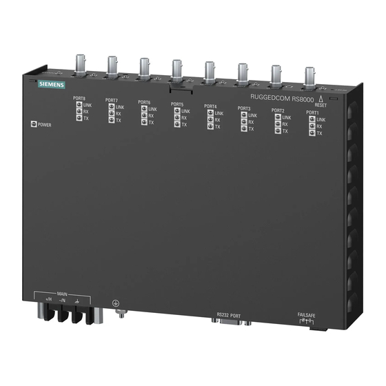
• Terminal blocks for reliable maintenance free connections • CSA/UL 60950 safety approved to 85 °C (185 °F) Section 1.2 Description The RUGGEDCOM RS8000H features various ports, controls and indicator LEDs on the front and rear panels for configuring and troubleshooting the device. Description... - Page 13 RUGGEDCOM RS8000H Chapter 1 Installation Guide Introduction Figure 1: Front and Rear Panels 1. POWER LED 2. RESET Button 3. Communication Ports 4. Port Status Indicator LEDS 5. RS232 Serial Console Port (DB9) POWER LED Illuminates when power is being supplied to the device. Color Description Green...
-
Page 14: Required Tools And Materials
RUGGEDCOM RS8000H, refer to Chapter 4, Communication Ports. Section 1.3 Required Tools and Materials The following tools and materials are required to install the RUGGEDCOM RS8000H: Tools/Materials Purpose AC or DC power cord (16 AWG) For connecting power to the device. CAT-5 Ethernet cables For connecting the device to the network. -
Page 15: Supported Fiber Optic Cables
Siemens also does not recommend using copper Ethernet ports to interface with devices in the field across distances that could produce high levels of ground potential rise (i.e. greater than 2500 V), during line-to-ground fault conditions. - Page 16 Chapter 1 RUGGEDCOM RS8000H Introduction Installation Guide Supported Fiber Optic Cables...
-
Page 17: Installing The Device
This product contains no user-serviceable parts. Attempted service by unauthorized personnel shall render all warranties null and void. Changes or modifications not expressly approved by Siemens Canada Ltd could invalidate specifications, test results, and agency approvals, and void the user's authority to operate the equipment. -
Page 18: Mounting The Device
Mounting the Device The RUGGEDCOM RS8000H is designed for maximum mounting and display flexibility. It can be equipped with connectors that allow it to be installed in a 48 cm (19 in) rack, 35 mm (1.4 in) DIN rail, or directly on a panel. -
Page 19: Mounting The Device To A Rack
RUGGEDCOM RS8000H Chapter 2 Installation Guide Installing the Device Figure 2: DIN Rail Mounting 1. Panel/DIN Rail Adaptor 2. DIN Rail 3. Screw Install one of the supplied screws on either side of the device to secure the adapters to the DIN rails. Section 2.2.2 Mounting the Device to a Rack To secure the device to a standard 48 cm (19 in) rack, do the following: Remove the four screws from the side of the device. -
Page 20: Mounting The Device To A Panel
Chapter 2 RUGGEDCOM RS8000H Installing the Device Installation Guide Figure 3: Rack Mounting 1. Rack Mount Adapter 2. Screw Insert the rack mount adapter and device assembly into the rack. NOTE Since heat within the device is channelled to the enclosure, it is recommended that 1 rack-unit of space, or 44 mm (1.75 in), be kept empty above the device. -
Page 21: Connecting The Failsafe Alarm Relay
Control of the failsafe relay output is configurable through ROS. One common application for this relay is to signal an alarm if a power failure occurs. For more information, refer to the ROS User Guide for the RUGGEDCOM RS8000H. The following shows the proper relay connections. -
Page 22: Connecting Power
1. Normally Closed 2. Common 3. Normally Open Section 2.4 Connecting Power The RUGGEDCOM RS8000H supports a single integrated high AC/DC or low DC power supply IMPORTANT! • For 88-300 VDC rated equipment, an appropriately rated circuit breaker must be installed. • For 100-240 VAC rated equipment, an appropriately rated circuit breaker must be installed. -
Page 23: Connecting Dc Power
RUGGEDCOM RS8000H Chapter 2 Installation Guide Installing the Device Figure 6: Terminal Block Wiring 1. Positive/Hot (+/H) Terminal 2. Negative/Neutral (-/N) Terminal 3. Surge Ground Terminal 4. Braided Ground Cable Connect the negative wire from the power source to the negative/neutral (-/N) terminal on the terminal block. - Page 24 Chapter 2 RUGGEDCOM RS8000H Installing the Device Installation Guide CAUTION! Electrical hazard – risk of damage to equipment. Before testing the dielectric strength (HIPOT) in the field, remove the braided ground cable connected to the surge ground terminal and chassis ground.
-
Page 25: Device Management
Connecting to the Device The following describes the various methods for accessing the ROS console and Web interfaces on the device. For more detailed instructions, refer to the ROS User Guide for the RUGGEDCOM RS8000H. Serial Console Port Connect a PC or terminal directly to the serial console port to access the boot-time control and ROS console interface. -
Page 26: Configuring The Device
Section 3.3 Resetting the Device The RUGGEDCOM RS8000H can be reset (rebooted) using the RESET button. The RESET button is recessed and can only be reached using a pin or small screwdriver. To reset the device, quickly press and release the RESET button with a pin. -
Page 27: Communication Ports
Communication Ports Communication Ports The RUGGEDCOM RS8000H can be equipped with various types of communication ports to enhance its abilities and performance. To determine which ports are equipped on the device, refer to the factory data file available through ROS. For more information on how to access the factory data file, refer to the ROS User Guide for the RUGGEDCOM RS8000H. -
Page 28: Fiber Optic Ethernet Ports
Chapter 4 RUGGEDCOM RS8000H Communication Ports Installation Guide Name Description Receive Data+ Receive Data- Transmit Data+ Reserved (Do Not Connect) Figure 12: RJ45 Ethernet Port Pin Configuration Reserved (Do Not Connect) Transmit Data- Reserved (Do Not Connect) Reserved (Do Not Connect) Case... -
Page 29: Technical Specifications
RUGGEDCOM RS8000H Chapter 5 Installation Guide Technical Specifications Technical Specifications This chapter provides important technical specifications related to the device. CONTENTS • Section 5.1, “Power Supply Specifications” • Section 5.2, “Failsafe Relay Specifications” • Section 5.3, “Copper Ethernet Port Specifications” • Section 5.4, “Fiber Optic Ethernet Port Specifications”... -
Page 30: Failsafe Relay Specifications
Chapter 5 RUGGEDCOM RS8000H Technical Specifications Installation Guide Section 5.2 Failsafe Relay Specifications Voltage Current 30 VAC 0.3 A 30 VDC 80 VDC 0.3 A Section 5.3 Copper Ethernet Port Specifications The following details the specifications for copper Ethernet ports that can be ordered with the RUGGEDCOM RS8000H. -
Page 31: Operating Environment
9/125 1310 MM = Multi-Mode, SM = Single-Mode Section 5.5 Operating Environment The RUGGEDCOM RS8000H is rated to operate under the following environmental conditions. Ambient Operating -40 to 85°C (-40 to 185 °F) Temperature Ambient Storage Temperature -40 to 85°C (-40 to 185 °F) - Page 32 Chapter 5 RUGGEDCOM RS8000H Technical Specifications Installation Guide 248.9 Figure 15: Overall Dimensions 479.4 464.5 Figure 16: Rack Mount Dimensions Dimension Drawings...
- Page 33 RUGGEDCOM RS8000H Chapter 5 Installation Guide Technical Specifications 274.3 264.2 Figure 17: Panel and Din Rail Mount Dimensions Dimension Drawings...
- Page 34 Chapter 5 RUGGEDCOM RS8000H Technical Specifications Installation Guide Dimension Drawings...
-
Page 35: Certification
• UL 60950-1 Information Technology Equipment – Safety – Part 1: General Requirements) Section 6.1.2 European Union (EU) This device is declared by Siemens Canada Ltd to comply with essential requirements and other relevant provisions of the following EU directives: Approvals... -
Page 36: Fcc
The device is marked with CE and European Explosive Atmosphere symbols and can be used throughout the European community. A copy of the CE Declaration of Conformity is available from Siemens Canada Ltd. For contact information, refer to “Contacting Siemens”. -
Page 37: Emc And Environmental Type Tests
Certification A copy of the Material Declaration is available online at https://support.industry.siemens.com/cs/ww/en/ view/109738831. Section 6.2 EMC and Environmental Type Tests The RUGGEDCOM RS8000H has passed the following EMC and environmental tests. IEC 61850-3 Type Tests Test Description Test Levels Severity Levels... - Page 38 5 kV AC Power ports 5 kV IEEE 1613 (C37.90.x) EMC Immunity Type Tests NOTE The RUGGEDCOM RS8000H meets Class 2 requirements for an all-fiber configuration and Class 1 requirements for copper ports. IEEE Test IEEE 1613 Clause Description Test Levels C37.90.3...
- Page 39 RUGGEDCOM RS8000H Chapter 6 Installation Guide Certification Environmental Type Tests Test Description Test Levels Severity Levels IEC 60068-2-1 Cold Temperature Test Ad -40 °C (-40 °F), 16 Hours IEC 60068-2-2 Dry Heat Test Bd 85 °C (185 °F), 16 Hours...
- Page 40 Chapter 6 RUGGEDCOM RS8000H Certification Installation Guide EMC and Environmental Type Tests...
Need help?
Do you have a question about the RUGGEDCOM RS8000H and is the answer not in the manual?
Questions and answers