Siemens SIMATIC NET RUGGEDCOM RST2228P Equipment Manual
Rugged ethernet switches
Hide thumbs
Also See for SIMATIC NET RUGGEDCOM RST2228P:
- Installation manual (58 pages) ,
- Installation manual (60 pages)

Related Manuals for Siemens SIMATIC NET RUGGEDCOM RST2228P


Summary of Contents for Siemens SIMATIC NET RUGGEDCOM RST2228P
- Page 1 Edition 10/2023 Equipment Manual SIMATIC NET Rugged Ethernet switches RUGGEDCOM RST2228P https://www.siemens.com/ruggedcom...
- Page 2 Preface Introduction Installing the device SIMATIC NET Communication ports Rugged Ethernet switches RUGGEDCOM RST2228P Device management Technical specifications Equipment Manual Certification 10/2023 C79000-G8976-1403-17...
- Page 3 Note the following: WARNING Siemens products may only be used for the applications described in the catalog and in the relevant technical documentation. If products and components from other manufacturers are used, these must be recommended or approved by Siemens. Proper transport, storage, installation, assembly, commissioning, operation and maintenance are required to ensure that the products operate safely and without any problems.
-
Page 4: Table Of Contents
Supplementary documentation ....................vi SIMATIC NET glossary ......................vi Registered trademarks ......................vi Warranty ..........................vii Training ..........................vii Customer support ......................... viii Contacting Siemens ......................viii Introduction ........................... 1 Feature highlights ....................1 Description ......................2 1.2.1 Article number ...................... 3 1.2.2... - Page 5 Table of contents Communication ports ......................41 Media modules ....................42 SFP transceivers ....................44 PoE Ports ......................45 Device management ......................47 Connecting to the device ..................47 IP address assignment ..................49 Configuring the device ..................49 Inserting/removing the CLP ................. 49 Technical specifications ......................
-
Page 6: Preface
Siemens' products and solutions undergo continuous development to make them more secure. Siemens strongly recommends that product updates are applied as soon as they are available and that the latest product versions are used. Use of product versions that are no longer supported, and failure to apply the latest updates may increase customer's exposure to cyber threats. -
Page 7: Supplementary Documentation
SIMATIC NET glossary The SIMATIC NET glossary describes special terms that may be used in this document. The glossary is available online via Siemens Industry Online Support (SIOS) at: https://support.industry.siemens.com/cs/ww/en/view/50305045 Registered trademarks The following and possibly other names not identified by the registered trademark sign ®... -
Page 8: Warranty
Warranty Siemens warrants this product for a period of five (5) years from the date of purchase, conditional upon the return to factory for maintenance during the warranty term. This product contains no user-serviceable parts. Attempted service by unauthorized personnel shall render all warranties null and void. -
Page 9: Customer Support
Call a local hotline center to submit a Support Request (SR). To locate a local hotline center, visit https://w3.siemens.com/aspa_app/?lang=en. Mobile app Install the Industry Online Support app by Siemens AG on any Android, Apple iOS or Windows mobile device and be able to: •... -
Page 10: Introduction
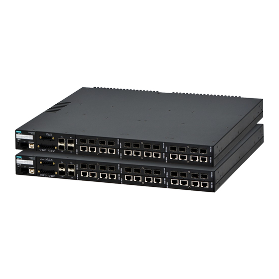
Introduction The RUGGEDCOM RST2228P is a utility grade, fully managed, industrial Ethernet switch designed to operate reliably in harsh environments. With a rugged metal enclosure and an optional conformal coating, the RUGGEDCOM RST2228P provides a high level of immunity to electromagnetic interference and heavy electrical surges, and can withstand extreme temperatures. -
Page 11: Description
Reliability in harsh environments • Immunity to EMI and heavy electrical surges • Zero-Packet-Loss technology • Supports Siemens FastConnect RJ45 Cabling System • -40 to 85 °C (-40 to 185 °F) operating temperature (fan-less) • Conformal coated printed circuit boards (optional) Description The RUGGEDCOM RST2228P features various ports, controls and indicator LEDs for connecting, configuring, and troubleshooting the device. -
Page 12: Article Number
Introduction 1.2.1 Article number Media modules Power supplies Chassis ground screw Figure 1.1 Device features 1.2.1 Article number The article number defines the device's hardware configuration. It is generated from the options selected in the RUGGEDCOM Selector at the time of ordering and printed on the product label affixed to the device. - Page 13 Introduction 1.2.1 Article number Option Description HI voltage (88-300 VDC/86-264 VAC) with screw terminal 24 VDC, plug terminal 48 VDC, plug terminal HI voltage (88-300 VDC/86-264 VAC) with plug terminal 12 VDC, screw terminal 12 VDC, plug terminal Power Supply 2 Option Description 24 VDC...
- Page 14 Introduction 1.2.1 Article number Option Description RUGGEDCOM RMM2972M-4SFP (4x SFP-slot with MACsec, Supporting 100BASE-FX, 1000BASE-X SFPs, SFPs are not included) RUGGEDCOM RMM2972-2RNA to support HSR/PRP functions; port A and B, 2 x 100/1000 Base-X SFPs (SFPs are not included) Slot 2 options Option Description RUGGEDCOM RMM2931-4 (Blank Module)
- Page 15 Introduction 1.2.1 Article number Slot 4 options Option Description RUGGEDCOM RMM2931-4 (Blank Module) RUGGEDCOM RMM2973-4RJ45 ( 4 x RJ45, 10/100/1000 BASE-TX) RUGGEDCOM RMM2973-4FC (4 x FastConnect (RJ45), 10/100/1000 BASE-TX) RUGGEDCOM RMM2973-4POE (4 x RJ45 supporting Power-over-Ethernet (POE, IEEE 802.3at), 10/100/1000 BASE-TX) RUGGEDCOM RMM2973-4PFC (4 x FastConnect (RJ45) supporting Power-over- Ethernet (POE, IEEE 802.3at), 10/100/1000 BASE-TX) RUGGEDCOM RMM2942-4LC2 (4 x 100MBit/s LC-interface, Optical: 100BASE-FX,...
-
Page 16: Orientation Options
Introduction 1.2.2 Orientation options Option Description RUGGEDCOM RMM2942-4LC2 (4 x 100MBit/s LC-interface, Optical: 100BASE-FX, Multi Mode fiber optic up to 2 kilometer, 1310nm) RUGGEDCOM RMM2972-4SFP (4 x SFP-slot, Supporting 100BASE-FX, 1000BASE-X SFPs, SFPs are not included) RUGGEDCOM RMM2973M-4RJ45 (4x RJ45 with MACsec, 10/100/1000 BASE-TX) RUGGEDCOM RMM2972M-4SFP (4x SFP-slot with MACsec, Supporting 100BASE-FX, 1000BASE-X SFPs, SFPs are not included) 1.2.2... - Page 17 Introduction 1.2.3 Status panel LEDs for 10GBase SFP+ transceivers (slot 0) Module slot locators LEDs for module ports Alarm status LED Power supply status LEDs PoE status LED ACO button Figure 1.5 Status panel Port status LEDs LEDs marked P1 to P4 indicate the status of the corresponding port. LEDs representing module ports are grouped and assigned the number of the corresponding module slot (1 to 6).
-
Page 18: Configuration And License Plug (Clp)
The CLP has a USB type C interface and can be used with the following devices that have a corresponding interface: • Siemens products • Personal computers (PCs), such as desktop PCs, tablet PCs, laptops, or smartphones Position The CLP slot is located below the status panel. -
Page 19: Usb Console Port
Introduction 1.2.5 USB console port Figure 1.6 Configuration License PLUG (CLP) Function In the startup phase: • When a CLP with no data (default setting) is plugged into a device, the device automatically saves its configuration data on the CLP. • If a CLP with data is plugged into a device, the device automatically adopts the configuration installed on the CLP. -
Page 20: Removable Media
Introduction 1.2.6 Removable media Figure 1.7 USB console port 1.2.6 Removable media The device supports removable media, allowing users to change or expand the capabilities of the device to suit their application requirements. Figure 1.8 Removable media Slot Description Four transceiver sockets for 1 Gigabit and 10 Gigabit SFP+ transceivers. 1 to 6 Six slots for removable modules. -
Page 21: Cabling Recommendations
Siemens also does not recommend using copper Ethernet ports to interface with devices in the field across distances that could produce high levels of ground potential rise (i.e. greater than 2500 V), during line-to-ground fault conditions. -
Page 22: Gigabit Ethernet 1000Base-Tx Cabling Recommendations
Introduction 1.4.2 Gigabit Ethernet 1000Base-TX cabling recommendations 1.4.2 Gigabit Ethernet 1000Base-TX cabling recommendations The IEEE 802.3ab Gigabit Ethernet standard defines 1000 Mbps Ethernet communications over distances of up to 100 m (328 ft) using all 4 pairs in category 5 (or higher) balanced, unshielded twisted-pair cabling. For wiring guidelines, system designers and integrators should refer to the Telecommunications Industry Association (TIA) TIA/EIA-568-A wiring standard that characterizes minimum cabling performance specifications required for proper Gigabit Ethernet operation. -
Page 23: Required Tools/Hardware
Introduction 1.5 Required tools/hardware Cable Type Wavelength (nm) Modal Bandwidth Distance (m) (MHz·km) 100Base-FX 1000Base-SX 10GBase-SR 1300 2000 — — Laser optimized. Required tools/hardware The following tools and hardware are required to install the device: Tools Tools Quantity Detail #1 Phillips screwdriver For removing/installing screw-type terminal block plugs and the terminal block cover. -
Page 24: Parts And Accessories
For grounding the device to safety Earth. Parts and accessories Parts and accessories, including removable media, kits, cables, and other components, are available through the RUGGEDCOM Selector [https://ruggedcom- selector.automation.siemens.com]. Media modules Available media modules are listed in the RUGGEDCOM Modules Reference Manual [https://support.industry.siemens.com/cs/ww/en/ps/24744/man]. SFP transceivers... - Page 25 Introduction 1.6 Parts and accessories Component Description Article number RUGGEDCOM RST2228P screw Kit containing screw-type 6GK6000-8HC06-0AA0 terminal plug connector kit terminal blocks, including one 7 POS terminal block for main power and one 5 POS terminal block for PoE/Failsafe Alarm Relay. Cables Component Description...
-
Page 26: Installing The Device
Installing the device This chapter describes how to install the device, including mounting the device, connecting power, and connecting the device to the network. DANGER Electrocution hazard – risk of serious personal injury and/or damage to equipment. Before performing any maintenance tasks, make sure all power to the device has been disconnected and wait approximately two minutes for any remaining energy to dissipate. -
Page 27: General Procedure
This product contains no user-serviceable parts. Attempted service by unauthorized personnel shall render all warranties null and void. Changes or modifications not expressly approved by Siemens Canada Ltd. could invalidate specifications, test results, and agency approvals, and void the user's authority to operate the equipment. -
Page 28: Unpacking The Device
Visually inspect each item in the package for any physical damage. Verify all items are included. Note If any item is missing or damaged, contact Siemens for assistance. Mounting the device The device can be mounted to a panel or standard 48 cm (19 in) rack. - Page 29 Installing the device 2.3 Mounting the device NOTICE Heat dissipation Heat generated by the device is channeled outwards from the enclosure. As such, it is recommended that 2.5 cm (1 in) of space be maintained on all open sides of the device to allow for some convectional airflow.
- Page 30 Installing the device 2.3 Mounting the device Mounting bracket Screw Figure 2.1 Rack mounting Insert the device into the rack. To make the modules and ports accessible from the front, insert the power supply side of the device first. Reverse the orientation to have the power supplies, management ports and LEDs accessible from the front.
- Page 31 Installing the device 2.3 Mounting the device Mounting bracket Screw Figure 2.2 Installing the mounting brackets Place the device against the panel and align the brackets with the mounting holes. Screw Mounting bracket Figure 2.3 Panel mounting Secure the brackets to the panel using two pan head screws per bracket. RUGGEDCOM RST2228P Equipment Manual, 10/2023, C79000-G8976-1403-17...
-
Page 32: Connecting The Failsafe Alarm Relay
The relay can also be triggered manually through RUGGEDCOM ROS. For more information, refer to the associated "RUGGEDCOM ROS Configuration Manual" [https://support.industry.siemens.com/cs/ww/en/ps/24744/man] associated with the installed software release. Connect the failsafe alarm relay to an I/O output to remotely monitor the relay state. - Page 33 Installing the device 2.4 Connecting the failsafe alarm relay Terminal block The failsafe alarm relay is connected via the PoE and failsafe alarm relay terminal block port. Figure 2.4 PoE and failsafe alarm relay terminal block port Terminal designations are marked on the device for easy identification. European-style (Euroblock) terminal block Screw-type terminal block Normally closed terminal...
- Page 34 Installing the device 2.4 Connecting the failsafe alarm relay If equipped, remove the PoE and failsafe alarm relay terminal block plug from the device. Connect the terminal block plug to an I/O device. European-style (Euroblock) terminal block Screw-type terminal block Figure 2.6 Failsafe alarm relay terminals Reinsert the terminal block plug into the device.
-
Page 35: Connecting Power
Installing the device 2.5 Connecting power Safety cover Screw Figure 2.8 Installing the safety cover Connecting power This section describes how to connect HI AC/DC and/or LO DC power to the device, as well as power for Power over Ethernet (PoE) ports. 2.5.1 Safety when connecting power DANGER... -
Page 36: Connecting Main Power
For the required wire gauge, refer to the power supply specifications in the "RUGGEDCOM Modules Reference Manual" [https:// support.industry.siemens.com/cs/ww/ en/ps/24744/man]. 7 POS power terminal block plug Device includes one European-style (Euroblock) or screw-type terminal block plug. Additional plugs are also available for purchase. - Page 37 Installing the device 2.5.2 Connecting main power Terminal block A single terminal block provides power to both power supply modules. The terminal block requires a 7 POS European-style (Euroblock) or screw-type terminal block plug. Separate positive, chassis ground, and negative terminals are available for each power supply module on the same terminal block plug.
- Page 38 Installing the device 2.5.2 Connecting main power • Install a circuit breaker rated no higher than 20 A between the device and the supply mains. • Whenever possible, use a separate circuit breaker for each power supply. • For maximum redundancy in a dual power supply configuration, use two independent power sources.
- Page 39 For more information, refer to the "RUGGEDCOM Modules Reference Manual" [https://support.industry.siemens.com/cs/ww/en/ps/24744/man]. Connect the power source to the power terminal block plug. Connect the line wire to the positive terminal Connect the ground wire to the chassis/ground terminal...
- Page 40 Installing the device 2.5.2 Connecting main power Note For examples of various wiring combinations, refer to "Wiring examples" (Page 32). Reinsert the terminal block plug into the device. For European-style (Euroblock) terminal block plugs, use a slotted screwdriver to tighten the captive screws. European-style (Euroblock) terminal block plug Screw-type terminal block plug Figure 2.13...
-
Page 41: Wiring Examples
Installing the device 2.5.2 Connecting main power Connect the device to ground (Protective Earth). For more information, refer to "Grounding the device" (Page 38). 2.5.2.1 Wiring examples The following illustrate how to connect single and dual power supplies to the device. Figure 2.15 Single high AC/DC power supply Figure 2.16... - Page 42 Installing the device 2.5.2 Connecting main power Figure 2.17 Dual high AC/DC power supply Figure 2.18 Dual low DC power supply RUGGEDCOM RST2228P Equipment Manual, 10/2023, C79000-G8976-1403-17...
-
Page 43: Connecting External Poe Power
For IEC 61850 compliance, use an IEC 61850 compliant PoE power supply with power cabling no longer than 3 m (118 in). Otherwise, Siemens recommends using the RUGGEDCOM RPS2410 switch-mode AC power supply. For more information about this power supply, refer to... - Page 44 Installing the device 2.5.3 Connecting external PoE power RPS2410 Operating Instructions [https://support.industry.siemens.com/cs/ww/en/ ps/29063]. Input power requirements Requirements for the external power source(s) are dependent on the IEEE 802.3 standard required by the application: IEEE standard Watts/ Power Input range Isolation port output...
- Page 45 Installing the device 2.5.3 Connecting external PoE power European-style (Euroblock) terminal block Screw-type terminal block Positive (+) terminal for PoE Negative (-) terminal for PoE Figure 2.21 PoE terminals Procedure Remove the safety cover. If equipped, remove the PoE and failsafe alarm relay terminal block plug from the device.
- Page 46 Installing the device 2.5.3 Connecting external PoE power Figure 2.22 PoE power supply wiring DANGER Electrocution hazard – risk of death, serious personal injury and/or damage to the device Make sure the supplied terminal block cover is always installed before the device is powered. Reinsert the terminal block plug into the device.
-
Page 47: Grounding The Device
Installing the device 2.5.4 Grounding the device Safety cover Screw Figure 2.24 Installing the safety cover 2.5.4 Grounding the device In accordance with UL 62368-1/CSA-C22.2 No. 62368-1, the device must be grounded via the grounding screw between the power module slots. Figure 2.25 Grounding screw Functional ground EMC disturbances are diverted to ground via the functional ground. - Page 48 Installing the device 2.5.4 Grounding the device Requirements Note Protective grounding during operation in compliance with UL 62368-1/CSA- C22.2 No. 62368-1 When operating in compliance with UL 62368-1/CSA-C22.2 No. 62368-1, the device must be connected to protective grounding via the grounding screw to meet UL approval requirements.
- Page 49 Installing the device 2.5.4 Grounding the device RUGGEDCOM RST2228P Equipment Manual, 10/2023, C79000-G8976-1403-17...
-
Page 50: Communication Ports
"Status panel" (Page 7). Use RUGGEDCOM ROS to determine which ports are equipped on the device. For more information, refer to the associated "RUGGEDCOM ROS Configuration Manual" [https://support.industry.siemens.com/cs/ww/en/ps/24744/man] associated with the installed software release. Figure 3.1 Slot designations... -
Page 51: Media Modules
ROS upon the next reboot. Available modules A variety of modules are available for use with the RUGGEDCOM RST2228P. For more information, refer to the "RUGGEDCOM Modules Reference Manual" [https://support.industry.siemens.com/cs/ww/en/ps/24744/man]. Requirements/restrictions Note the following restrictions: Module type Maximum allowed Copper Ethernet modules... - Page 52 Communication ports 3.1 Media modules Removing a media module To remove a media module, do the following: Make sure power to the device has been disconnected and wait approximately two minutes for any remaining energy to dissipate. [Optional] If the device is installed in a rack, remove it from the rack. Using a Torx T10 screwdriver, loosen the screw that secures the media module to the chassis.
-
Page 53: Sfp Transceivers
"RUGGEDCOM SFP Transceivers Reference Manual" [https:// support.industry.siemens.com/cs/ww/en/ps/24744/man]. Note Only use SFP transceivers approved by Siemens for RUGGEDCOM products. Siemens accepts no liability as a result of performance issues related in whole or in part to third-party components. Installation/removal... -
Page 54: Poe Ports
For more information, refer to the associated "RUGGEDCOM ROS Configuration Manual" [https:// support.industry.siemens.com/cs/ww/en/ps/24744/man] associated with the installed software release. For information about connecting the external power supply, refer to "Connecting external PoE power"... - Page 55 Communication ports 3.3 PoE Ports RUGGEDCOM RST2228P Equipment Manual, 10/2023, C79000-G8976-1403-17...
-
Page 56: Device Management
It may cause damage to the contact pins of the RJ45 ports. For a permanent solution, use Siemens 6XV1870-3Qxxx certified cables (manufactured December 2019 or after) or equivalent. Siemens recommends using Siemens certified cables and connectors for Siemens RUGGEDCOM products. - Page 57 USB Type-B console port. For more information, refer to the associated "RUGGEDCOM ROS Configuration Manual" [https://support.industry.siemens.com/cs/ww/en/ps/24744/man] associated with the installed software release. Use the following settings to connect to the port:...
-
Page 58: Ip Address Assignment
The device is configured by default to connect with a DHCP server. Once connected, an IP address is assigned automatically. For more information, refer to the "ROS Configuration Manuals" [https:// support.industry.siemens.com/cs/ww/en/ps/24744/man] associated with the installed software release. • Set an IP address with SINEC PNI Use the SINEC PNI (Primary Network Initialization) tool to manually assign a static IP address to the device. - Page 59 Device management 4.4 Inserting/removing the CLP NOTICE Mechanical/electrical hazard – risk of damage to the CLP • Do not expose the CLP to extreme temperatures or humidity • Do not expose the CLP to large magnetic or static electric fields • Do not bend or drop the CLP NOTICE Operating hazard –...
- Page 60 Device management 4.4 Inserting/removing the CLP Protective cover Figure 4.2 Removing the CLP Remove the CLP from the slot. If necessary, insert a standard screwdriver between the bottom edge of the CLP and the device to move the CLP forward. Insert the protective cover or a new CLP to prevent the ingress of dust and dirt.
- Page 61 Device management 4.4 Inserting/removing the CLP Figure 4.3 Installing the CLP Remove the protective cover from the CLP port. Insert the CLP into the CLP port. [Optional] Restart the device. RUGGEDCOM RST2228P Equipment Manual, 10/2023, C79000-G8976-1403-17...
-
Page 62: Technical Specifications
Technical specifications This section provides important technical specifications related to the device. Note Technical specifications related to modules are detailed separately in the "RUGGEDCOM Modules Reference Manual" [https://support.industry.siemens.com/cs/ ww/en/ps/24744/man]. For technical specifications related to SFP transceivers, refer to the "RUGGEDCOM SFP Transceivers Reference Manual"... -
Page 63: Poe Output Specifications
Technical specifications 5.3 PoE output specifications Internal fuse Power supply Voltage rating Ampere Fuse type Fuse delay rating % of ampere Opening time rating 12 VDC 85 VAC/VDC 12 A Very fast acting 100% 4 hours (minimum) 200% 5 seconds (maximum) 24 VDC 125 VAC/VDC 10 A... -
Page 64: Failsafe Alarm Relay Specifications
Technical specifications 5.4 Failsafe alarm relay specifications Failsafe alarm relay specifications NOTICE Alarm switching voltage The alarm switching voltage must be less than the Safety Extra Low-Voltage (SELV) to meet safety requirements. Maximum switching voltage Rated switching current Isolation 30 VDC 1.5 kVAC 125 VDC 0.15 A... -
Page 65: Mechanical Specifications
Technical specifications 5.7 Mechanical specifications Operating temperature may vary based on the limitations of installed SFPs. For information about SFP transceiver temperature ratings, refer to the "RUGGEDCOM SFP Transceivers Reference Manual" [https://support.industry.siemens.com/cs/ww/en/ps/24744/ man]. Non-condensing. Mechanical specifications Weight 8.0 kg (18 lbs) - Page 66 Technical specifications 5.8 Dimension drawings 462.2 43.6 23.5 Figure 5.2 Rack mount dimensions 43.6 462.2 23.5 Figure 5.3 Panel mount dimensions RUGGEDCOM RST2228P Equipment Manual, 10/2023, C79000-G8976-1403-17...
- Page 67 Technical specifications 5.8 Dimension drawings RUGGEDCOM RST2228P Equipment Manual, 10/2023, C79000-G8976-1403-17...
-
Page 68: Certification
Assessed (UKCA) marking. The marking is printed on the body of the device. 6.1.2 European Union (EU) This device is declared by Siemens Canada Ltd. to comply with essential requirements and other relevant provisions of the following EU directives: •... -
Page 69: Tüv Süd
Certification 6.1.3 TÜV SÜD • EN 61000-3-3 Electromagnetic compatibility (EMC) – Part 3-3: Limits – Limitation of voltage changes, voltage fluctuations and flicker in public low-voltage supply systems, for equipment with rated current ≤16 A per phase and not subject to conditional connection •... -
Page 70: Ised
6.1.6 ISED This device is declared by Siemens Canada Ltd. to meet the requirements of the following ISED (Innovation Science and Economic Development Canada) standard: • CAN ICES-3 (A)/NMB-3 (A) 6.1.7... -
Page 71: Iso
Quality management systems – Requirements 6.1.9 RoHS This device is declared by Siemens Canada Ltd. to meet the requirements of the following RoHS (Restriction of Hazardous Substances) directives for the restricted use of certain hazardous substances in electrical and electronic equipment: EU RoHS Directives (EU) 2011/65 and (EU) 2015/863 •... -
Page 72: Emc And Environmental Type Tests
Certification 6.2 EMC and environmental type tests EMC and environmental type tests The RUGGEDCOM RST2228P has passed the following EMC and environmental tests. EMC type test for IEC 61850-3 Note IEC 61850-3 Class 1/Class 2 Conformance • In the case of an all fiber port configuration, this product meets all Class 2 requirements. - Page 73 2 kV HV impulse Signal ports 5 kV (fail-safe relay output) DC power ports 5 kV AC power ports 5 kV PoE power ports 1 kV Siemens-specified severity levels RUGGEDCOM RST2228P Equipment Manual, 10/2023, C79000-G8976-1403-17...
- Page 74 Certification 6.2 EMC and environmental type tests EMC immunity type tests per IEEE 1613 Description Test levels Severity levels Enclosure contact ± 8 kV Enclosure air ± 15 kV Radiated RFI Enclosure ports 35 V/m (80% modulation) Fast transient Signal ports ±...
- Page 75 Certification 6.2 EMC and environmental type tests Test Description Test levels Severity levels IEC 60255-21-3 Seismic Method A, class 2 Class 2 IEC 60529 Ingress protection IP3x IEC 60068-2-31 Free fall Test Ec 25 cm RUGGEDCOM RST2228P Equipment Manual, 10/2023, C79000-G8976-1403-17...
- Page 76 For more information Siemens RUGGEDCOM https://www.siemens.com/ruggedcom Industry Online Support (service and support) https://support.industry.siemens.com Industry Mall https://mall.industry.siemens.com Siemens Canada Ltd. Digital Industries Process Automation 300 Applewood Crescent Concord, Ontario, L4K 4E5 Canada © 2023 Siemens Canada Ltd. Subject to change...
Need help?
Do you have a question about the SIMATIC NET RUGGEDCOM RST2228P and is the answer not in the manual?
Questions and answers