Table of Contents
Advertisement
Quick Links
Advertisement
Table of Contents

Related Manuals for Mitsubishi Electric Evolution+ s-MEXT


Summary of Contents for Mitsubishi Electric Evolution+ s-MEXT
- Page 1 Control system Evolution+ Version ME38 s-MEXT TECHNICAL MANUAL Italian is the original language. The other languages versions are translation of the original. English English For safe and correct use, carefully read this manual and the installation, use and maintenance manual of the unit.
- Page 2 Version 38...
- Page 3 Before carrying out any operation on the machine, you must carefully read this manual and make sure you understand all the instructions and information given Keep this manual in a known and easily accessible place to refer to as necessary during the entire life-span of the unit.
-
Page 4: Table Of Contents
1 ..INTRODUCTION ................................9 ..OPERATING REQUIREMENTS ....................................9 ..GENERAL FUNCTIONS ......................................9 ..UNITS CONTROLLED ......................................10 2 ..USER INTERFACE ..............................11 USER TERMINAL ........................................11 ..2.1.1 ..Technical features ......................................11 2.1.2 ..Buttons functions ......................................12 2.1.3 .. - Page 5 4 ..TEMPERATURE ADJUSTMENT CONSIDERATIONS ..................... 133 ..MANAGEMENT OF THE LIMITS OF THE COOLING SETPOINT ........................133 ..TEMPERATURE PROBES MANAGEMENT ................................ 134 4.2.1 ..Configuration of the installed probes ................................134 4.2.2 ..Type of temperature calculation ..................................135 4.2.3 ..
- Page 6 11.8.2 Fan adjustment based on delivery temperature ............................165 11.8.3 Fan adjustment based on temperature differential ............................165 12 ..DAMPER MANAGEMENT ............................167 12.1 DELIVERY DAMPER ......................................167 12.2 DIRECT FREE COOLING DAMPER ..................................167 12.3 TEMPERATURE ADJUSTMENT IN UNITS WITH DIRECT FREECOOLING ..................... 168 12.3.1 S-MEXT unit regulation with Direct Free Cooling ............................
- Page 7 17.7 ACTIVE FAN ON STAND-BY ....................................201 17.7.1 Introduction ....................................... 201 17.7.2 Operation ....................................... 201 17.8 TEMPERATURE AND HUMIDITY AVERAGE MANAGEMENT .......................... 203 17.8.1 Introduction ....................................... 203 17.8.2 Average calculation ....................................... 203 17.8.3 Enable the use of the averagne ..................................203 17.9 H&L LOCAL TEMPERATURE PROTECTION ..............................
- Page 8 SYMBOLS A number of symbols are used to highlight some parts of the text that are of particular importance. These are described below. WARNING: Information on the occurrence of situations/operations which, if ignored or not duly acted upon, could put not only the Unit but also the functions of the Software and the various electronic parts at risk.
-
Page 9: Introduction
INTRODUCTION 1.1 Operating requirements The software described in this document was designed for use with precision air-conditioning units such as “Close Control” units (for data processing centres). The software was designed for use on the following control systems: • Control board EVOLUTION+ – Small with user terminals and PGD1 graphic interface. •... -
Page 10: Units Controlled
1.3 Units controlled The software in question can be installed on the following version of air-conditioning units: Type and diagram Description Unit code Features SPLIT TYPE These direct expansion units use refrigerant for the transfer of heat. The air in the room is, •... -
Page 11: User Interface
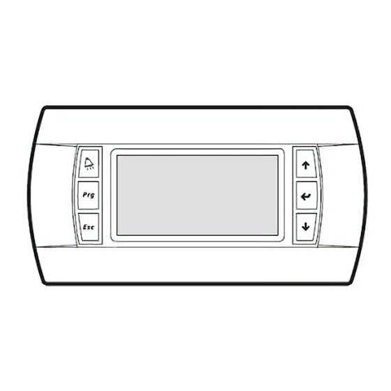
USER INTERFACE 2.1 User terminal 2.1.1 Technical features The user interface comprises: • 132x64 pixel backlit LCD display (22 columns, 8 rows). • 6 backlit buttons. The connection between the microprocessor board and the user terminal involves a 4-pole telephone cable equipped with RJ11 jack connector. -
Page 12: Buttons Functions
2.1.2 Buttons functions Name Function • Everywhere: accesses the Event menu where [ALARM] alarm and signalling events are displayed. • In the "Event" menu: restores the normal condition. • In the main loop: accesses the “Main” group. • In the groups: Accesses the selected menu [PRG] or group •... - Page 13 • In the shared keyboard mode, this [ALARM + combination allows to share screenshots and ESC] parameters among LAN connected units. [UP + ENTER • Press for 5 seconds to set the LAN address of + DOWN] the user terminal. •...
-
Page 14: Key Led Management
2.1.3 Key LED management The key led indicators turn on in the following instances: Keys Name Description The LED is fixed in case of alarm and flashing in case of signal. Once the [ALARM] key is pressed, the LED [ALARM] becomes fixed. - Page 15 Main Main Loop Group Unit Unit [ESC] [ESC] / [ENTER] Selection Menu Setpoint Setpoint [ESC] [ESC] / [ENTER] Selection Menu In/Out In/Out [ESC] [ESC] / [ENTER] Selection Menu Clock Clock [ESC] [ESC] / [ENTER] Selection Menu...
- Page 16 Main User Group Group Serial Serial [ESC] [ESC] / [ENTER] Selection Menu Alarm out Alarm out [ESC] [ESC] / [ENTER] Selection Menu Scheduler Scheduler [ESC] [ESC] / [ENTER] Selection Menu Info Info [ESC] [ESC] / [ENTER]...
- Page 17 Main Service Group Group Regulat. Regulations [ESC] [ESC] / [ENTER] Selection Menu FreeCool. Free Cooling [ESC] [ESC] / [ENTER] Selection Menu Settings Settings [ESC] [ESC] / [ENTER] Selection Menu [ESC] [ESC] / [ENTER] Selection Menu ...
-
Page 18: Password Management
Main Factory Group Group Config. Config. [ESC] [ESC] / [ENTER] Selection Menu Functions Functions [ESC] / [ENTER] [ESC] Selection Menu Compress. Compressor [ESC] [ESC] / [ENTER] Selection Menu Valve Valve [ESC] [ESC] / [ENTER] Selection Menu... - Page 19 “User” Password 1234 (modifiable) “Service” Password 9990 (modifiable) “Factory” Password 0000009982 (modifiable) The “Factory” password is managed using the Service software, which for each controller configures a password, which is then saved in the job. The password is only available to the after-sales service. Once at the last digit of the password, by pressing the [ENTER] key the software will compare the entered password with those stored in its memory.
-
Page 20: Language Management
2.2.3 Language management The controller pCO5+ has an additional memory containing all the supported languages. During programming, all the languages are loaded to the controller and the end user can select the language to display. The table below shows the languages available and their international codes: English Italian German... - Page 21 Unit - About Once the operation has finished, the masks will appear in the selected language. Evolution+ The installed language can be checked in the “About” mask of the “Unit” menu. Code ME 38.00 EN Perform all the steps of the procedure. If even just one file is omitted, the following faults may occur: Select one iup file No “.iup”...
-
Page 22: Status Display Masks
2.3 Status display masks The various status display masks provide: • a complete overview regarding the status of the unit; • useful information for the unit maintenance operator. In the main loop there are, in addition to the main mask and the Temperature Probes mask, only the masks that allow you to view the status of the various functions active on the unit, if any. - Page 23 Mask of the terminal Description PAC-IF013B-Client Client PAC-IF013B-E status Pressing [ENTER] will take to the section containing additional Client PAC-IF card information Active step: Mode: COOLING Status: Online icon will flash showing the “PAC-IF code:” message followed by In case of alarm, the the alarm code from the PAC-IF card.
- Page 24 Mask of the terminal Description Humidifier Display of the operating status of the internal humidifier. 000.0kg/h 00.0A 0000µS/cm Alarm Warning code:00 code:0 Visible only if internal humidifier is present. LAN STATUS Local network (LAN) status display mask. This mask is displayed on all units in the same pLAN group. •...
- Page 25 Mask of the terminal Description PAC-IF013B-E Client Client PAC-IF info mask: • Status Status: • Mode Mode: COOLING • Communication Step: Adjustment step Communication: Online Information visible only with S-MEXT unit enabled. PAC-IF013B-E Client Client PAC-IF info mask: • Suction temperature probe (TH11). •...
-
Page 26: Unit Menu
Mask of the terminal Description PAC-IF013B-E Server1 Server1 PAC-IF info mask: • Compressor status. Compressor Status: • Pre-defrost. Predefrost: • Defrost. Defrost: ACTIVE • Selfprotection: ACTIVE Self protection. PAC-IF SW version Software ver. 000001 Information visible only with S-MEXT unit and Server 1 enabled. 2.3.2 Unit Menu Accessible from: “Main”... - Page 27 Mask of the terminal Description Unit - Remote 1 T+H Mask that displays the value of the serial remote probe 1 (address 129). 30.2°C 53.0% Status: Online Visible if at least one serial remote probe is configured Unit - Remote 2 T+H Mask that displays the value of the serial remote probe 2 (address 130).
- Page 28 Mask of the terminal Description Unit - Int. Fan Status Display of the status of the internal EC 1 and 2 fans communicating via Modbus. Fan 1 00 00000 In case of alarm or signal coming from the fan, both the code (alarm on the left, Turned On RPM:0800 signal on the right) and the corresponding description are visible.
- Page 29 Mask of the terminal Description Unit - Energy Anlz. 1 Mask that displays the network analyser active energy and hour counter. Energy: 0075600kWh Time: 0000002h Visible if the network analyser is present and configured. Unit - Energy Anlz. 2 Mask that displays the values detected by the network analyser 2. The supply voltage, absorbed current and absorbed active power are displayed.
- Page 30 Mask of the terminal Description Unit - KIPlink Display of information on the KIPlink Ethernet network. Ethernet channel: IP: 192.168.030.001 Sub:255.255.255.000 Gw: 000.000.000.000 Unit - KIPlink Display of information on the KIPlink Wi-Fi network. WiFi channel: IP: 192.168.030.001 Sub:255.255.255.000 Gw: 000.000.000.000 Unit - KIPlink Display of the status and main information of the network of the KIPlink Priority Network Info...
-
Page 31: In/Out Menu
2.3.3 In/Out Menu Accessible from: “Main” group. Mask of the terminal Description Access mask to “In/Out” menu. For the meaning of the various inputs and outputs, please refer to In/Out the “input/output configuration tables”. In/Out - Anlg. Inputs Displays the status of the universal inputs. - Page 32 Mask of the terminal Description In/Out – Modbus Addr. Displays the modbus address used for communication with each of the enabled Supply T+H Probe: devices. EXP 1: 008 EXP 3: 010 Visible only if one or more of the devices listed are present. In/Out –...
-
Page 33: Log Menu
2.3.4 Log Menu Accessible from: “Main” group. Mask of the terminal Description Access mask to “Alarms Log” menu. History History Selection of the alarm type from the display history. Filter It is possible to select from Compressor, Circuit, Unit, and System alarms. for events: For a description of the Location field, please refer to the “Events”... -
Page 34: Main Status Display Masks
2.4 Main status display masks 2.4.1 Main Mask Visible from: Main loop. The figure below shows the main mask layout, including the (numbered) areas in which it is divided: Figure 2-7: representation of the main mask. The area above displays the hour and the date. It also displays room humidity and temperature (only when the probe is installed) in real time (also in case the average value mode for the local LAN units connected should be active). - Page 35 Area 1: general machine status Unit off Unit operating in normal mode Unit operating in maximum fan speed mode for fan alarm Normal operation Unit operating on steady capacity Maximum flow reached mode Minimum flow reached Unit operating on Normal operation steady residual ∆P Minimum flow reached mode...
- Page 36 Area 3: type of event; only displayed in case of active event: Fire/Smoke or water leak. Return humidity probe faulty. Wrong phase sequence. Remote humidity probe faulty. Water leaks (flooding). Differential air pressure transducer faulty. Lack of air flow. Feed air temperature probe faulty. Return temperature probe faulty.
- Page 37 Area 4: Cold resources currently in operation: At least one compressor of a Mr. Slim unit is active. If icon flashes intermittently, the request for compressor start-up is in process but a countdown is active for safety timing purposes (see the corresponding section in the protection function chapter). Area 5: Free Cooling resources currently in operation: Direct Free Cooling damper in adjustment.
- Page 38 Area 7: Cold resources currently in operation: First electric heater step active/Heater active. Second electrical element step active. Third electrical element step active. Electric heaters Post-Ventilation function active (flashing icon). Area 8: current unit status (ON/OFF): This indicator can also be used to switch the unit on/off. Area 9: BSM address of the unit (where the BMS one is engaged).
-
Page 39: Active Functions Mask
2.4.2 Active Functions Mask Visible from: Main loop. INFORMATION: The mask can be displayed only if one of the functions described below is active. The appearance of the mask is signalled by the presence of the icon on the main mask. The image below shows the representation: Figure 2-8: mask display. - Page 40 Areas 1 and 2: flashing of all the active functions Icon Function Meaning Time bands active. Time bands active. Time Bands Activated Free Cooling active. Unit in Free Cooling mode. Free Cooling Activated Free Cooling is disabled Direct Free Cooling is disabled from the supervisor. from the supervisor.
- Page 41 Icon Function Meaning High temperature pLAN The unit is in pLAN rescue mode due to the high rescue active. temperature limit being exceeded. High Temperature pLAN Rescue Activated Low temperature pLAN The unit is in pLAN rescue mode due to the low rescue active.
-
Page 42: Safety Reduction Load Mask, S-Mext Unit
2.4.3 Safety Reduction Load mask, s-MEXT unit Visible from: main loop ZONE ZONE ZONE ZONE 4 Figure 2-8: Safety Reduction Load mask representation. Zone 1: fan status Icon Meaning Normal fan operation. Fan in Alert mode (Flashing): • With SRL (LP) active: The speed of the fans increases with 2 alert steps Zone 2: status of the unit controlled by the PAC-IF interface Icon... -
Page 43: Lan Aplmask
2.4.4 LAN APLMask Visible from: Main loop. This mask allows the status of the following two functions to be displayed: • “Active Pressure Load”. • “H&L Local Pressure Protection”. ZONE 1 ZONE 2 ZONE 3 ZONE 5 ZONE 5 ZONE 4 ZONE 7 Figure 2-13: representation of the “LAN APL”... -
Page 44: Parameter Changing Masks
Zone 5: average pressure status: Icon Meaning The unit is not using the average pressure of the LAN for adjustment. The unit is using the average pressure of the LAN for adjustment. Zone 6: local pressure status: Icon Meaning The unit is not using the local pressure for adjustment. Local The unit is using the local pressure for adjustment. -
Page 45: [P10] Config. Menu
2.5.2 [P10] Config. Menu Accessible from: “Factory” group. Mask of the terminal Description Par.N. Access mask to Config. Menu. (Configuration). Config. Config --------------- P10.33 Parameter for setting the type of unit. Unit type: [Perimetral | Rack Cooler | Cooling Door | Modular Perimetral | TLC] Perimetral - - - - - - - - - - - Cold type set:... - Page 46 Mask of the terminal Description Par.N. Config. --------------- P10.53 Parameter for setting the type of gas used in direct expansion circuits Unit gas type: [R410A – R32]. R410A Visible only on units with at least one direct expansion circuit. 10.53 Config.
- Page 47 Mask of the terminal Description Par.N. Config --------------- P10.48 Parameter for managing the phase sequence control in power supply Phase sequence 2 mana- line 2. gement on unit: 10.48 Config. --------------- P10.50 Parameter for indicating the number of return air NTC probes installed Number of return NTC in the unit.
-
Page 48: [P11] Functions Menu
2.5.3 [P11] Functions Menu Accessible from: “Factory” group. Mask of the terminal Description Par.N. Access mask to “Functions” menu. Functions Functions --------------- P11.01 Air flow control type. Air flow control type: Disabled | Constant Range | Constant DeltaP | Read Only DeltaP | Read Only Rate]. Disabled Always disabled on PMESH units. -
Page 49: [P12] Compressor Menu
2.5.4 [P12] Compressor Menu Accessible from: “Factory” group. Mask of the terminal Description Par.N. Access mask to “Compressor” menu. Compressor Compressor --------------- P12.01 Parameter for setting Minimum compressor ON time. Compressor Minimum ON time: 180s --------------- P12.02 Parameter for setting Minimum compressor OFF time. Compressor 12.01 Minimum OFF time: 180s... -
Page 50: [P13] Valve Menu
2.5.5 [P13] Valve Menu Accessible from: “Factory” group. Mask of the terminal Description Par.N. Access mask to “Valve” menu. Valve Valve --------------- P13.05 Enable the electronic thermostatic valve (EEV). Electronic Expansion Valve (EEV) enable: 13.05 Version 38... -
Page 51: [P14] Menu Safety
2.5.6 [P14] Menu Safety Accessible from: “Factory” group. Mask of the terminal Description Par.N. Access mask to “Safety” menu. Safety Safety --------------- P14.03 Delay time of the probe alarms. Temperature probe alarms delay time:060s --------------- P14.04 Delay time of the low pressure alarms. Low Pressure 14.03 alarms delay time:180s... -
Page 52: [P15] Safety 2 Menu
2.5.7 [P15] Safety 2 Menu Accessible from: “Factory” group. Mask of the terminal Description Par.N. Access mask to “Safety 2” menu. Safety 2 Safety 2 --------------- P15.13 Parameter for setting the type of inhibition of the dehumidification due to Low return temperature low return temperatures. -
Page 53: P--] Default Menu
2.5.8 [P--] Default Menu Accessible from: “Factory” group. Mask of the terminal Description Par.N. Access mask to the “Default” menu (initialisation of the factory parameters). Default Default This restores the default values. Wipes the memory and restores the default values of the parameters. The chiller Default Setup must then be programmed with the parameter set during factory testing. - Page 54 Mask of the terminal Description Par.N. Regulations --------------- P20.03 Ventilation modulation start delay. Fan modulation delay: 120s 20.03 Regulations --------------- P20.04 Start regulation delay. Fan regulation delay: 060s 20.04 Regulations --------------- P20.05 Integral adjustment time. Regulation integral time: 900s Only visible on units without inverter compressor. 20.05 Regulations --------------- P20.08...
- Page 55 Mask of the terminal Description Par.N. Regulations --------------- P20.24 Cooling setpoint minimum limit. Cooling setpoint lower limit: 18.0°C --------------- P20.25 Cooling setpoint maximum limit. Cooling setpoint 20.24 upper limit: 32.0°C 20.25 Regulations --------------- P20.26 Heating setpoint minimum limit. Heating setpoint lower limit: 12.0°C --------------- ------...
- Page 56 Mask of the terminal Description Par.N. Regulations --------------- P20.98 Maximum Neutral Switch-On Zone for increasing the resources for delivery air Max Increase N.Zone control. for Tsupply reg:03.0°C --------------- P20.99 Maximum Neutral Switch-Off Zone for decreasing the resources for delivery air Max Decrease N.Zone control.
- Page 57 Mask of the terminal Description Par.N. Regulations --------------- P20.83 Function for control of ventilation (special function 02): Temperature type, fan • regulation function: disabled; • return temperature; • delivery temperature; • temperature delta (Return T. - Discharge T.). 20.83 Regulations --------------- P20.84 Temperature band for fan control.
-
Page 58: [P21] Free Cooling Menu
2.5.10 [P21] Free Cooling Menu Accessible from: “Service” group Mask of the terminal Description Par.N. ↑ Access mask to the “Free Cooling” menu. Free Cooling ← ↓ Mask displayed if the Free Cooling mode is not present. Unit Without Free Cooling --------------- P21.21 Value of the cooling ramp at which to have maximum opening of the Direct Free Cold ramp value for... - Page 59 Mask of the terminal Description Par.N. FC – FC damper --------------- P21.17 Parameter for setting the humidity hysteresis for inhibition of direct Free Cooling. Humid. Diff to deact. damper: 01.0%RH Visible only if direct free-cooling inhibition for high humidity is enabled. 21.17 FC –...
-
Page 60: [P22] Settings Menu
2.5.11 [P22] Settings Menu Accessible from: “Service” group. Mask of the terminal Description Par.N. Access mask to “Settings” menu. Settings Settings --------------- P22.01 Low temperature alarm setpoint. Low temperature alarm setpoint: 10°C --------------- P22.02 High temperature alarm setpoint. High temperature alarm 22.01 setpoint:... - Page 61 Mask of the terminal Description Par.N. Settings 22.31 ------------ P22.31-42 Configuration of the ETH channel of the KIPlink module. 22.32 KIPlink 22.33 Ethernet channel 22.34 192.168.030.001 22.35 SUB: 255.255.255.000 22.36 000.000.000.000 22.37 22.38 22.39 22.40 22.41 22.42 Settings 22.62 ------------ P22.62-73 Configuration of the WiFi channel of the KIPlink module.
- Page 62 Mask of the terminal Description Par.N. Settings --------------- P22.55 Enable the offline alarm of port BMS1. BMS1 offline alarm enable: --------------- P22.56 Timeout for offline detection of port BMS1. BMS1 offline 22.55 detection timeout:015s 22.56 Settings --------------- P22.57 Enable the offline alarm of port BMS2. BMS2 offline alarm enable: --------------- P22.58...
- Page 63 Mask of the terminal Description Par.N. Settings --------------- P22.85 Parameter for setting the type and reset of the Fire/Smoke event. Fire/smoke event type: Visible only if smoke/fire sensor management is enabled. 22.85 Settings --------------- P22.88 Enable the control of the external damper alarm (not controlled by the logic). External dumper alarm enable: --------------- ------...
- Page 64 Mask of the terminal Description Par.N. Settings – Pwd change Sets a new “Service” password. Insert a new Attention: the value set in this field is the one and only to access the “Service” Service password: group. 0000 Settings – About This mask contains the reference information of the software [Code ME 38.00 Evolution+ EN].
-
Page 65: [P22] Settings 2 Menu
2.5.12 [P22] Settings 2 Menu Accessible from: “Service” group. Mask of the terminal Description Par.N. Access mask to “Settings2” menu. Settings2 Settings --------------- P29.01 Hazardous high temperature alarm setpoint. Very High temperature alarm setpoint: 10°C 29.01 2.5.13 [P23] Fan Menu Accessible from: “Service”... - Page 66 Mask of the terminal Description Par.N. --------------- P23.74 Parameter for configuring the counter of the number of trips per hour due to Air Flow alarm manual pressure switch air flow missing alarm. rearm after count: --------------- P23.75 Parameter to set the number of interventions per hour for the passage from the AirFlow alarms cnt per automatic reset alarm to the manual reset.
- Page 67 Mask of the terminal Description Par.N. --------------- P23.11 Interval for acquisition of the air differential pressure. Air pressure diff. scan time: 060s --------------- P23.12 Enable the condensation control function. Condensation control 23.11 enable: 23.12 --------------- P23.61 Enable the heater post-ventilation function. Post-ventilation for el.
-
Page 68: [P24] Adjustments Menu
2.5.14 [P24] Adjustments Menu Accessible from: “Service” group. Mask of the terminal Description Par.N. Access mask to “Adjustments” menu. Adjustments Adjustments Parameter for ambient temperature probe calibration. --------------- P24.01 Return air temperature probe adj.: 0.0°C --------------- P24.02 Parameter for ambient humidity probe calibration. Return air humidity Visible only if the air return T/H probe is enabled. - Page 69 Mask of the terminal Description Par.N. Adjustments --------------- P24.44 Parameter for calibrating the remote temperature / humidity sensor 4. Remote 4 T+H temp. probe adj.: 0.0°C --------------- P24.45 Remote 4 T+H humidity 24.44 probe adj.: 00.0% Visible only if at least four serial remote T+H probes are configured. 24.45 Adjustments --------------- P24.23...
-
Page 70: P25] Demand Limit Menu
Mask of the terminal Description Par.N. Adjustments --------------- P24.48 Parameter for setting the external air temperature reading resolution. Extern. T+H hum. Probe updating diff.: 0.5% --------------- P24.49 Parameter for setting the external air humidity reading resolution. Extern. T+H tem. Probe updating diff.: 0.5°C 24.48... -
Page 71: [P26] Lan Menu
2.5.16 [P26] LAN Menu Accessible from: “Service” group. Mask of the terminal Description Par.N. Access mask to “LAN” (Local Area Network) menu. This mask indicates that the LAN menu parameters can be edited only on the Priority unit. Editable only from the Master unit (Add.01) Only displayed on Secondary units. - Page 72 Mask of the terminal Description Par.N. --------------- P26.14 Parameter for configuring the time of deactivation of the Hot & Cold Spot function Delay before after returning within the limits. protection OFF with Treturn in range: 300s Visible only if Hot&Cold spot management is enabled. 26.14 --------------- P26.15 Parameter for configuring the time of activation of the Hot &...
- Page 73 Mask of the terminal Description Par.N. --------------- P26.25 Parameter for setting the network units that will be taken into consideration by LAN Unit group enabling: logic. ----- (bit N: Unit with N address controller). Units: Param. Value: 000031 Visible only if LAN is enabled. 26.25 --------------- P26.26 Parameter for setting priority boards (Priority).
-
Page 74: [P--] Manual Menu
2.5.17 [P--] Manual Menu Accessible from: “Service” group Mask of the terminal Description Par.N. Access mask to “Manual” menu. This menu contains the masks for the manual control of the unit. Manual This menu is used to reset the network analyser counts and reset the operating hours and the start counts of the various unit components. - Page 75 Mask of the terminal Description Par.N. Manual ---------------------- Manual request for the activation of the dehumidification function. Dehumidification manual activation: ---------------------- Visible only if dehumidification management is enabled, if manual operation is ---------------------- enabled and the unit is running. Manual ---------------------- pLAN Standby Funct.
-
Page 76: [P27] Optional Menu
2.5.18 [P27] Optional Menu Accessible from: “Service” group. Mask of the terminal Description Par.N. Access mask to the “Optional” menu. Optional Optional --------------- P27.02 Enable the heating elements. Electric heater enable: --------------- P27.03 Heating elements type. Electric heater [ON/OFF]. - Page 77 Mask of the terminal Description Par.N. Optional --------------- P27.29 Parameter for setting the minimum difference between humidification setpoint and Diff. between setpoint dehumidification setpoint. humidification and dehumidification: Visible only if both the humidifier and the dehumidification function are enabled. 27.29 Optional --------------- P27.11 Enable the delivery air damper.
- Page 78 Mask of the terminal Description Par.N. Optional --------------- P27.24 Parameter for setting the maximum setpoint offset cooling. Maximum compensation of cooling set: 02.0°C Visible only if the setpoint compensation function is enabled. 27.24 Optional --------------- P27.25 Parameter for setting the start point of heating setpoint compensation. Temp.
-
Page 79: [P28] Regulations 2 Menu
2.5.19 [P28] Regulations 2 Menu Accessible from: “Service” group. Mask of the terminal Description Par.N. Access mask to “Regulations 2” menu. Regulations Regulations 2 Mask displayed when none of the parameters of this menu for the unit are available. -
Page 80: [P30] Serial Menu
2.5.20 [P30] Serial Menu Accessible from: “User” group. Mask of the terminal Description Par.N. Access mask to “Serial” menu (Serial connections). Serial Serial --------------- P30.01 Enable the BMS supervisor. BMS supervision enable: 30.01 Serial --------------- P30.02 BMS1 port address. BMS1 address: --------------- P30.03 BMS1 port protocol type. - Page 81 Mask of the terminal Description Par.N. Serial --------------- P30.11 Enabling Free Cooling operation block by BMS. FC Stop by Supervisor enable: Visible only on units with Direct Free Cooling. 30.11 Serial GSM modem management Modem password 0000 GSM Modem password request. Numbers in address Maximum number of numbers in the phonebook.
-
Page 82: [P31] Alarm Out Menu
2.5.21 [P31] Alarm out Menu Accessible from: “User” group. Mask of the terminal Description Par.N. Access mask to “Alarm out” menu (Addressing of alarms on the digital outputs). Alarm out Alarm out addressing --------------- P31.01 Logic of alarm contact A. Alarm out A [NO | NC]. - Page 83 Mask of the terminal Description Par.N. Alarm out addressing --------------- P31.14 Addressing of the delivery air temperature probe alarm on digital output. (140) Supply Air Temp. Probe Fail./Disc.: 31.14 Alarm out addressing --------------- P31.16 Addressing of the external air temperature probe alarm on digital output. (144) Outdoor Air Temp Probe Fail./Disc.: 31.16...
- Page 84 Mask of the terminal Description Par.N. ---------------------- --------------- P31.49 Addressing of the flooding alarm/signal on digital output. (010/510) Flood Alarm/ Flood Warning: 31.49 Alarm out addressing --------------- P31.50 Addressing of the LAN interrupted alarm on digital output. (520) LAN Interrupted: 31.50 Alarm out addressing --------------- P31.94...
- Page 85 Mask of the terminal Description Par.N. Alarm out addressing --------------- P31.68 Addressing of the BMS2 port offline alarm on digital output. (712) BMS2 Bus Offline: 31.68 Alarm out addressing --------------- P31.70 Addressing of the Remote T+H probe temperature sensor alarm on digital output. (121) Remote Temp.
-
Page 86: [P32] Scheduler Menu
2.5.22 [P32] Scheduler Menu Accessible from: “User” group. Mask of the terminal Description Par.N. Access mask to the “Scheduler” menu (Time bands manager). Scheduler Scheduler --------------- P32.01 Enable the time bands. Scheduler enable: 32.01 2.5.23 [P--] Info Menu Accessible from: “User”... -
Page 87: [P33] Alarm Out Menu 2
2.5.24 [P33] Alarm out Menu 2 Accessible from: “User” group. Mask of the terminal Description Par.N. Access mask to “Alarm out 2” menu (Addressing of alarms on the digital outputs). Alarm out Alarm out addressing 2 Mask displayed when none of the parameters of this menu for the unit are available. No Alarm out 2 Parameters Available Alarm out addressing 2... - Page 88 Mask of the terminal Description Par.N. Alarm out addressing 2 --------------- P33.53 Addressing of the remote serial humidity probe 2 alarm on digital output. (127) Remote 2 umidity out of range out: --------------- P33.54 Addressing of the remote serial temperature probe 2 alarm on digital output. (122) Remote 2 temp.
- Page 89 Mask of the terminal Description Par.N. Alarm out addressing 2 --------------- P33.76 Addressing of the delivery humidity above maximum limit alarm on digital output. (543) Supply Humid. above max limit: --------------- P33.77 Addressing of the delivery humidity below minimum limit alarm on digital output. (542) Supply Humid.
-
Page 90: [P50] Setpoint Menu
Mask of the terminal Description Par.N. Alarm out addressing 2 Addressing of PAC–IF Client proble alarm (0:A – 1:None – 2:B) ---------------P33.91 (050)GasLeakdetected alarmonoutput:A Addressing of PAC–IF Server 1 system alarm (0:A – 1:None – 2:B) 33.91 2.5.25 [P50] Setpoint Menu Accessible from: “Main”... -
Page 91: [P900] Clock Menu
Mask of the terminal Description Par.N. Setpoint --------------- P50.07 Dehumidification setpoint during LAN out of range. Dehumdific. Setpoint with LAN limits: 75%RH --------------- P50.08 Humidification setpoint during LAN out of range. Humdific. Setpoint 50.07 with LAN limits: 35%RH 50.08 Setpoint --------------- P50.09 Parameter for minimum room temperature and dehumidifier off. - Page 92 Mask of the terminal Description Par.N. Clock Selecting the type of time band programming. [Standard | Advanced]. Time band Advanced programming manages four different daily time bands (A, B, C, D); each programming: type can be personalised and each is independent from the others. Advanced Standard programming only allows for the use of A-type time bands.
- Page 93 Mask of the terminal Description Par.N. Clock Setting of the first and second type B daily time bands. 902.01 Band 1B 902.02 Time 00:00 / 05:00 In the example, the unit regulates from 05.00 am to 10.00 pm. During the 902.03 Sp C 24.0°C H 20.0°C remaining period the unit is off.
- Page 94 Mask of the terminal Description Par.N. Clock Setting of the third and fourth type C daily time bands. 903.13 Band 3C 903.14 Time 00:00 / 00:00 In the example, the unit is always off. 903.15 Sp C 24.0°C H 20.0°C 903.16 903.17 Band 4C...
- Page 95 Mask of the terminal Description Par.N. Clock Setting of the fifth and sixth type D daily time bands. 904.25 Band 5D 904.26 Time 00:00 / 00:00 In the example, the unit is always off. 904.27 Sp C 24.0°C H 20.0°C 904.28 904.29 Band 6D...
-
Page 96: Parameter Table
2.6 Parameter Table The numbering of the parameters is divided by menu: • 1x corresponds to the menus of the “Factory” group; • 2x corresponds to the menus of the “Service” group; • 3x corresponds to the menus of the “User” group; •... - Page 97 Par.N. Description Default U.M. Min. Max. 10.30 Start scale value of low pressure transducer 10.31 End scale value of low pressure transducer Configuration of the external T probe on I/O PCO (0:Disabled – 1:Enabled) 10.20 Initial logo (0:Evolution – 1:De' Longhi – 2:ICS – 3:Neutral – 4:EATON) 10.22 Inversion logic of cold water valve (0:NO –...
-
Page 98: Service Group
2.6.2 Service Group Par.N. Description Default U.M. Min. Max. Regulation probe configuration (0:Return – 1:Delivery) 20.01 20.02 Fan start delay after power on 20.03 Ventilation modulation start delay 20.04 Start regulation delay 20.05 Integral adjustment time (units without inverter) Dirty filter sensor configuration (0:Disabled – 1:Enabled) 20.08 Smoke sensor configuration (0:Disabled –... - Page 99 Par.N. Description Default U.M. Min. Max. 20.72 T&H limits alarm delay when unit ON Safety Reduction Load LP function configuration (0:Disabled – 1:Enabled) 20.73 20.74 Circuit 1 Safety Reduction Load LP function activation setpoint 20.75 Circuit 1 Safety Reduction Load LP function differential 20.76 Step time for Circuit 1 Safety Reduction Load LP function Auxiliary humidity probe address 129 configuration (0:Disabled –...
- Page 100 Par.N. Description Default U.M. Min. Max. Type of KIPlink module (0:MASTER_eth off_wifi off – 1:CLIENT_eth off_wifi 22.30 off – 2:MASTER_eth on_wifi off – 3:CLIENT_eth on_wifi off – 4:MASTER_eth off_wifi on – 5:CLIENT_eth off_wifi on – 6:MASTER_eth on_wifi on – 7:CLIENT_eth on_wifi on – 8:MASTER bridge – 9:CLIENT bridge) 22.31 Part 1 IP address of Ethernet channel KIPlink module...
- Page 101 Par.N. Description Default U.M. Min. Max. 22.76 Delay for decrease for air delivery control 22.77 Delay between two decreases for air delivery control 1200 Port used for the Fieldbus (1:Fbus1 – 2:Fbus2) 22.78 22.79 Air flow alarm detection delay from ventilation start 22.92 Air flow alarm activation delay without compressors or heaters active 22.80...
- Page 102 Par.N. Description Default U.M. Min. Max. 23.66 Pressure regulation differential for Constant Flow 23.67 Constant DeltaP adjustment setpoint 23.69 Pressure regulation differential for Constant DeltaP 23.68 Minimum internal fan speed in constant DeltaP (maximum nominal speed reduction) 10.11 23.70 Fan analogue outlet variation step 23.72 Start-up of the fan at maximum speed if the adjustment starts with the return temperature higher than the corresponding setpoint (0:Disabled –...
- Page 103 Par.N. Description Default U.M. Min. Max. 24.37 Delivery temperature 2 T+H probe calibration °C -9.9 24.38 Delivery temperature 3 T+H probe calibration °C -9.9 24.39 Delivery temperature 4 T+H probe calibration °C -9.9 24.46 External serial temperature TH probe calibration °C -9.9 24.47...
- Page 104 Par.N. Description Default U.M. Min. Max. Enable APL operation in case of pressure transducer alarm (0:Disabled – 26.19 1:Enabled) Enable the H&L Local Pressure Protection function (0:Disabled – 1:Enabled) 26.20 26.21 High local pressure function On differential 26.22 Low local pressure function On differential 26.23 Time before protection Off when the temperature is between the high and low local pressure limits...
- Page 105 Par.N. Description Default U.M. Min. Max. 27.32 Line 2 input current ampere transformation ratio 32767 Enable the setpoint compensation function (0:Disabled – 1:Enabled) 27.20 Type of signal for setpoint compensation (0:0-1VDC – 1:0-5 VDC – 2:0.5- 27.21 4.5VDC – 3:0-20mA – 4:4-20mA – 5:T+H Remote – 6:T+H External - 99.29 7:Temp.
-
Page 106: User Group
2.6.3 User Group Par.N. Description Default U.M. Min. Max. 30.01 Supervision presence configuration 30.02 BMS address configuration BMS protocol configuration (0:Standard – 1:Modbus – 2:GSM Modem – 30.03 3:LON – 4:Bacnet – 5:TCP/IP – 6:WinLoad) BMS baud rate configuration (0:1200 – 1:2400 – 2:4800 – 3:9600 – 4:19200 30.04 –... - Page 107 Par.N. Description Default U.M. Min. Max. Addressing of the eeprom alarm on digital output (0:A – 1:None – 2:B) 31.55 Addressing of the maintenance alarm on digital output (0:A – 1:None – 2:B) 31.56 Addressing of the dirty filters alarm on digital output (0:A – 1:None – 2:B) 31.58 Addressing of the circuit 1 frost–free protection alarm on digital output (0:A –...
- Page 108 Par.N. Description Default U.M. Min. Max. 33.56 Addressing of the remote 3 T+H probe humidity alarm (0:A - 1:None - 2:B) 33.57 Addressing of the remote 4 T+H probe temperature alarm (0:A - 1:None - 2:B) 33.58 Addressing of the remote 4 T+H probe humidity alarm (0:A - 1:None - 2:B) Addressing of the remote 2 T+H probe offline alarm (0:A –...
-
Page 109: Setpoint Menu
2.6.4 Setpoint menu Par.N. Description Default U.M. Min. Max. 50.01 Setpoint cooling °C 99.27 99.28 50.02 Hot setpoint °C 20.26 99.27 50.03 Dehumidification setpoint 99.02 50.04 Humidification setpoint 99.03 50.05 Cold setpoint for LAN limits °C 50.01 50.06 Hot setpoint for LAN limits °C 50.02 50.07... - Page 110 Par.N. Description Default U.M. Min. Max. 901.05 Winter temperature setpoint in time band 1 A °C 99.23 99.24 901.07 Unit status in time band 2 A (1:Off - 2:Adjustment) 99.19 99.20 901.08 End of time band 2 A (Hours) 901.02 901.09 End of time band 2 A (Minutes) 901.10...
- Page 111 Par.N. Description Default U.M. Min. Max. 901.38 End of time band 7 A (Hours) 901.32 901.39 End of time band 7 A (Minutes) 901.40 Summer temperature setpoint in time band 7 A °C 99.21 99.22 901.41 Winter temperature setpoint in time band 7 A °C 99.23 99.24...
- Page 112 Par.N. Description Default U.M. Min. Max. 902.13 Unit status in time band 3 B (1:Off - 2:Adjustment) 99.19 99.20 902.14 End of time band 3 B (Hours) 902.08 902.15 End of time band 3 B (Minutes) 902.16 Summer temperature setpoint in time band 3 B °C 99.21 99.22...
- Page 113 Par.N. Description Default U.M. Min. Max. 902.45 End of time band 8 B (Minutes) 902.46 Summer temperature setpoint in time band 8 B °C 99.21 99.22 902.47 Winter temperature setpoint in time band 8 B °C 99.23 99.24 902.49 Unit status in time band 9 B (1:Off - 2:Adjustment) 99.19 99.20 902.50...
- Page 114 Par.N. Description Default U.M. Min. Max. 903.20 End of time band 4 C (Hours) 903.14 903.21 End of time band 4 C (Minutes) 903.22 Summer temperature set point in time band 4 C °C 99.21 99.22 903.23 Winter temperature set point in time band 4 C °C 99.23 99.24...
- Page 115 Par.N. Description Default U.M. Min. Max. 903.52 Summer temperature set point in time band 9 C °C 99.21 99.22 903.53 Winter temperature set point in time band 9 C °C 99.23 99.24 903.55 Unit status in time band 10 C (1:Off - 2:Adjustment) 99.19 99.20 903.56...
- Page 116 Par.N. Description Default U.M. Min. Max. 904.27 End of time band 5 D (Minutes) 904.28 Summer temperature set point in time band 5 D °C 99.21 99.22 904.29 Winter temperature set point in time band 5 D °C 99.23 99.24 904.31 Unit status in time band 6 D (1:Off - 2:Adjustment) 99.19...
-
Page 117: Limiting Parameters
2.6.6 Limiting parameters Par.N. Description Minimum limit that can be set for the internal fan speed (Calculated as P10.10 – P10.11%) 99.01 Minimum limit that can be set for the dehumidification setpoint 99.02 (Calculated as P50.04 + 5) Maximum limit that can be set for the dehumidification setpoint 99.03 (Calculated as P50.03 - 5) 99.04... -
Page 118: Events Masks
2.7 Events masks Press the [ALARM] key once to enter the “Event” menu showing the alarm and signalling event messages along with their codes. 15:00:01 08/04/20 A003 Fire/Smoke Presence Alarm Reset: Manual Location: Plant Blocked: Unit If there is more than one event, scroll the menu using the [UP] and [DOWN] keys. Press [ESC] to exit this menu. In order to reset an event, press the [ALARM] key another time. -
Page 119: Table Of Alarm And Signalling Events
Action: El. Heater Block of the electric heater or heat resource involved in the event. Action: Function Block of the function involved in the event. Key of the “Action” column for the “Function” category. Block of the Free Cooling function Block of the function regarding the output air temperature limit. - Page 120 Event Code Display description Details Reset Time Position Action Time Remote T+H probe 2 temperature sensor Event A122 fault. Remote Temp. Probe2 Failed/Disconnected Visible only when the Remote T+H probe 2 is present. Remote T+H probe 3 temperature sensor Event A123 fault.
- Page 121 Event Code Display description Details Reset Time Position Action Time Event A142 Water In Temp. Probe Cold water temperature probe fault. Failed/Disconnected Event A143 Circuit 1 outlet cold water temperature Water Out Temp. Probe probe fault Failed/Disconnected External air temperature probe faulty. Event A144 Outdoor Air T.
- Page 122 Event Code Display description Details Reset Time Position Action Time Incorrect phase sequence for fan 5. Event A160 Fan 5 CI/- Visible only if the unit has at least one EC Phase Fault fan. Fan 1 motor blocked Event A161 Fan 1 CI/- Visible only if the unit has at least one EC...
- Page 123 Event Code Display description Details Reset Time Position Action Time Temperature problem on fan 2. See the third row for details on the Event A172 problem. Fan 2 CI/- Heat Problem Visible only if the unit has at least one EC fan.
- Page 124 Event Code Display description Details Reset Time Position Action Time Event A188 PAC-IF Client disconnection alarm (Mr. PAC-IF Client Slim connection board) offline alarm Event A189 PAC-IF Server 1 disconnection alarm (Mr. PAC-IF Server1 Slim connection board) offline alarm I/O expansion 4 disconnection alarm Event A191 (serial connection).
- Page 125 Event Code Display description Details Reset Time Position Action Time Circuit 2 low pressure transducer fault Event A321 alarm. Circ. 2 LP Probe Failed/Disconnected Visible only if the transducer is present. Event A322 Circuit 2 low pressure alarm from pressure Circ.
- Page 126 Event Code Display description Details Reset Time Position Action Time Current problem on fan 6. See the third row for details on the Event A457 problem. Fan 6 CI/- Voltage Problem Visible only if the unit has at least one EC fan.
- Page 127 Event Code Display description Details Reset Time Position Action Time Signals that the delivery humidity is below Event S542 the minimum set level. Supply Humidity Below Min. Limit Visible only if the delivery air T/H probe is present. Signals that the delivery humidity is above Event S543 the maximum set level.
-
Page 128: Pac-If013B-E Board Alarms Table
2.7.2 PAC-IF013B-E board alarms table EVOLUTION+ PAC-IF013B-E board alarms Code Display description Type Code Description A Event A188 PAC-IF Client PAC-IF Client disconnection alarm (Mr. Slim connection board) offline alarm Event A189 PAC-IF Server1 PAC-IF Server 1 disconnection alarm (Mr. Slim connection board) offline alarm Loss of communication between remote controller and Client PAC- E0/E4... - Page 129 EVOLUTION+ PAC-IF013B-E board alarms Code Display description Type Code Description A probes alarm Liquid temperature sensor faulty TH2 (Slave 1 PAC-IF013B-E) Two-phase temperature sensor faulty TH5 (Slave 1 PAC-IF013B-E) Version 38...
-
Page 130: Start Of The Unit
START OF THE UNIT 3.1 Software upload Upon initial installation the cards must be programmed by uploading the software inside the “Flash” memory. This operation can be performed only using the “Service” software. The computer communicates with the pCO board using a USB-RS485 converter. 3.2 Unit power supply WARNING: Connect the unit to the power supply at least 8 hours before starting it. - Page 131 Digital input: This procedure can only be used if the digital input is present and if the parameter "Enable On/Off from digital input" in the "Regulations" menu has been set to "Yes". The "Regulations" menu can be accessed using the "Service" password. Proceed as follows: •...
-
Page 132: Start Of Automatic Adjustment
Turn A Turn B Turn C Week Adjustment Unit off Figure 3-1: Example ofdaily time band settings. Using the supervision protocol This procedure can only be used if the serial card is present. Check in the “User menu” that the parameters “Serial line enabling” and “On/Off enabling from supervisor” are set to “Yes”. Proceed as follows: •... -
Page 133: Temperature Adjustment Considerations
TEMPERATURE ADJUSTMENT CONSIDERATIONS The heating and cooling resources are managed on the basis of the temperature values measured by the return or delivery probe depending on the parameter settings. This temperature is compared with the set value (setpoint), and based on the difference, the devices may activate. -
Page 134: Temperature Probes Management
Without Heating sources (°C) ambient P20.24 P20.25 P50.01 WITH Heating sources (°C) ambient P20.24 P20.25 P50.02 P50.01 Figure 4-1: Charts of management of the setpoint limits. 4.2 Temperature probes management The application can manage one NTC return probe, one NTC delivery probe, one T/H serial return air probe, one T/H serial delivery air probe and up to 4 TH serial remote probes at the same time. -
Page 135: Type Of Temperature Calculation
4.2.2 Type of temperature calculation Based on the number of the configured probes, and the ones selected for the calculations, it will be possible to define the type of calculation completed by the application for the return and delivery temperature. The following 4 calculation modes are available for both: •... -
Page 136: Setpoint Offset
4.3 Setpoint offset This function allows automatic cooling and heating setpoint variation within a preset range, based on a signal sent to the unit controller. The function monitors in real time the input value (analogue signal, or temperature read by the remote 1 T+H probe, or temperature red by the external T+H probe, or the calculated return temperature), and calculates the offset value based on the parameters. - Page 137 Note: The previous chart shows a condition when the entered P27.27 value is below 0. If the probe selected for compensation fails, the setpoints will assume the non–compensated values as per parameters P50.01 and P50.02. In case of compensation through analogue input, the only available parameters will be the maximum P27.24 and P27.27 offset values, as the minimum and maximum limits correspond to the signal sent to the controller (0–1V, 0–5V, 0.5–4.5V, 0–20mA, 4–20mA).
-
Page 138: Cooling
COOLING 5.1 Cooling in s-MEXT units 5.1.1 Communication with the Mr Slim unit During the management and control of Mr Slim units, it is necessary to use interface cards (PAC-IF013B-E), through which the s-MEXT unit will send commands and request information from the Mr. Slim units. There are 2 possible types of connections for the use of Mr Slim units, depending on the number of them being used with the s- MEXT unit. -
Page 139: Cold Request Generation
5.1.4 Cold request generation The external unit control logic requires DIP temperature control. This logic operates as follows. ) (t Setpoint ∑ Error ∑ Process Output Figure 5-3: PID control logic operation. The control variable is the return or delivery temperature and the controlled variable is the adjustment ramp (defined in values from 0 to 100%). - Page 140 In view of the long wait between two variations of request to the Client PAC-IF card, there is a time delay of 5 seconds before sending a power variation, to make sure that the value is the actually requested value, and not subjected to transitional and sudden request variations.
-
Page 141: Lack Of Voltage
5.1.5 Lack of voltage The behaviour of the machine differs depending on whether it is a power failure of the Client or Server Mr. Slim unit. Lack of voltage Unit not powered Description 5 minutes after the event (loss of voltage) has occurred, the alarm code sent by Mr. -
Page 142: Minimum Delivery Temperature Limit
5.2 Minimum delivery temperature limit 5.2.1 Objectives Setting a minimum limit to the delivery temperature may be a request justified by the presence, very close to the unit delivery outlet, of devices that are sensitive to relatively low temperatures. The delivery temperature can only fall excessively if there is a sudden decrease in the temperature of the cold coil (evaporation temperature or, more likely, the temperature of the chilled water coming from a chiller). -
Page 143: Heating
HEATING 6.1 Heating resources The sources available for ambient air heating are the following: • Heating elements, managed as simple on/off loads. INFORMATION: The activation of the electric heaters forces the demand for ventilation at the maximum speed. This speed is defined as the greater between P10.10 and that generated by the ventilation control logics. -
Page 144: Post-Ventilation Function For The Electric Heaters
6.3 Post-ventilation function for the electric heaters This function, available for all the units equipped with electric heaters, is for cooling the electric heaters when the unit is turned off and the electric heaters are still active. When the OFF command is given (at the keyboard, by the supervisor, or remotely), the fan continues to run at nominal speed for a period of time set in the parameter (P23.61). -
Page 145: Adjustment With Temperature Provided By The Supervisor
ADJUSTMENT WITH TEMPERATURE PROVIDED BY THE SUPERVISOR INFORMATION: To enable the parameter for this adjustment (P30.09) it will be necessary to enable the supervision. This adjustment is available only for the port BMS1 and compatible only with the Modbus protocol. The function involves use of the temperature from a Supervisor system. -
Page 146: Dehumidification
DEHUMIDIFICATION 8.1 Dehumidification start-up Activating dehumidification happens through an On/Off logic according to the step reported in the following diagram. Dehumidify P50.03 ambient P20.20 Differential Figure 8-1: dehumidification start-up graph. The dehumidify setting parameter is under the “Set point” menu. The dehumidify differential parameter is under the “Regulations”... -
Page 147: Upper Limit
8.2.2 Upper limit In the first case, the following must be observed: Even in the absence of an upper limit the temperature increase cannot continue indefinitely, as with the increase of the room temperature: • the sensible capacity of the unit increases and the latent capacity increases; •... -
Page 148: Lower Limit
8.2.3 Lower limit There is also an absolute lower limit for dehumidifier operation; it is managed according to a step whose position on the room temperature axis depends on the presence or absence of resources for post-heating, if any. If there are no heat resources available (heaters or hot water coil), the lower limit step refers to the cooling setpoint, as shown in the following figure: Dehumidify (°C) -
Page 149: Combination Of The Limits
8.2.4 Combination of the limits Combined use of the high and low limits is shown in the graph below: Dehumidify Dehumidify (°C) ambient P50.01 2 * Differential P20.18 2 * Differential P20.18 Figure 8-5: dehumidification temperature limit graph. Dehumidify Dehumidify (°C) P50.02 P50.01... -
Page 150: Post - Heating
The following graph shows how this function works: (°C) ambien t P50.09 Compressor Time (min) P14.11 P14.11= Maxi m um dehumidification cycle ON time P14.12 P14.12= Minimum delay for new dehumidification cycle Figure 8-7: timed dehumidification adjustment graph. Dehumidification therefore remains enabled for a time equal to the “Max DH time” parameter (expressed in minutes). When this time elapses the compressor is disabled for a time equal to the “Max waiting time”... -
Page 151: Dehumidification Setpoint Limit
Step 3 Step 2 Step 1 P50.02 - P50.02 - (°C) P50.02 ambient P20.19 P20.19 P20.19 Figure 8-8: post heating resource management. All the resources, if present, can be selected from the “Config” menu accessible through the “Factory” password. The following table summarises the methods used to manage the heating resources both in heating and in post-heating: Heating resources present Central heating resources Post-heating resources... - Page 152 Operation in the two conditions described above can be summarised with the chart below: Limite setpoint deumidi f ica dipendente da setpoint UMIDIFICA Umidifica Deumidifi c a P50.03 ambiente P50.04 Differenziale P20.20 Differenziale P20.21 5% fisso Limite minimo setpoint deumidifica P14.10 Figure 8-9: chart of management of the limit of the dehumidification setpoint.
-
Page 153: Humidification
HUMIDIFICATION 9.1 Introduction The software allows the humidification to be performed by the integrated humidifier installed on the unit. Activating the humidifying device is enabled only when all the following conditions are met: • adjustment consent is active; • There is no humidity probe alarm. •... -
Page 154: Vapour Production Regulation
9.2.2 Vapour production regulation The production of vapour by the integrated humidifier constantly depends on the humidification demand according to ambient humidity adjustment. The programme adjusts humidity according to the reading of the humidity probe, the humidity setpoint and the humidity differential. -
Page 155: Periodic Drain
9.2.6 Periodic drain It is recommended that this function is enabled through parameter P27.16 when using water rich in substances such as humus and slit. The humidifier drains and automatically replaces the water in the cylinder to prevent the accumulation of these substances. -
Page 156: Alarm Management
9.2.8 Alarm management The terminal displays the active alarms. The Alarms and Signals relative to humidifier operation are detailed in the controller alarms section. A crucial point of humidifier operation is excess current control. In fact, whenever voltage is applied to the boiler electrodes after a period of shutdown, short but very intense current peaks can be observed. -
Page 157: Temperature And Humidity Measurement
10 TEMPERATURE AND HUMIDITY MEASUREMENT 10.1 Return air T+H probe This probe is available for all the units that require humidity control and allows the enabling of the following functions: • dehumidification; • Humidification. It also allows the reading of the humidity, in addition to temperature, and can be used for the calculation of the return temperature. The probe is connected via Modbus to the Fieldbus port defined using the controller parameters at address 128. -
Page 158: External T+H Probe
10.4 External T+H Probe This probe is available for all the units. It also allows the reading of the external temperature and humidity. Probe 1 is connected via Modbus to the Fieldbus port defined using the parameter of the controller at address 133. 11 INTERNAL AIR FAN MANAGEMENT 11.1 Introduction The unit is fitted with EC radial evaporating fans. -
Page 159: Automatic Speed Regulation Function
11.5 Automatic speed regulation function This function allows to automatically adjust EC radial fan speed. It may follow two logics: • Constant flow rate regulation. • Constant residual ∆P regulation. For these two logics, a differential pressure transducer is used and positioned so as to detect the pressure value used for regulation. - Page 160 When configuring the unit the project flow value and the number of fans in the unit are entered. The programme also requires that the fan flow is never less than the set rated flow. The parameters entry mask is under the “Fan” menu accessible through the “Service” password. The purpose of regulation is to keep the flow rate constant when there is an increase in the loss of load, with reference to the graph below.
-
Page 161: Constant Residual ∆P Regulation
Constant residual ∆P regulation 11.5.2 The pressure transducer is positioned according to the following figure: Figure 11-5: chart for positioning the pressure taps for the differential pressure probe. The controller adjusts following the chart below: INCREASE speed NO Action DECREASE speed Differential pressure P23.67 Differential... - Page 162 The purpose of regulation is to keep the residual ∆P constant when there is an increase in the counter–pressure, with reference to the following graph. Figure 11-7: constant head fan operation curve Starting from nominal work point (A), the increase in counter-pressure (due, for instance to a damper closing) causes a shift in the fan work point along the curve towards point B, with the ensuing increase in pressure.
-
Page 163: Calibrating The Constant Flow Function
11.5.3 Calibrating the constant flow function To allow greater adjustment precision a calibration mask has been included, which evaluates the difference between the real value read by the transducer and the value to reach. Calibration is performed during production testing using the following mask: Fan - Const. -
Page 164: Command From Supervisor
11.6 Command from supervisor This function allows direct control of the internal fans of the unit by sending a ventilation command to the controller from the supervision system. The fan speed is changed according to the last command received. This means that if communication fails between the controller and the supervisor, the fans will continue to run at the same speed of the command received before communication failure. -
Page 165: Fan Adjustment Based On Temperature (Former Fan Special Function 02)
11.8 Fan adjustment based on temperature (former fan special function 02) Fan speed can be controlled on the basis of: • return temperature; • delivery temperature; • temperature differential (return temperature - delivery temperature). 11.8.1 Fan adjustment based on return temperature This special function permits modulation of the EC fan using the return air (ambient air) probe as the adjustment temperature, at the same time adjusting the actuators using the delivery air temperature. - Page 166 The following diagram shows possible use of the function by a plant: Remote ambient air temperature probe ROOM EQUIPMENT Delivery air temperature probe Figure 11-8: diagram showing the possible use of the fan adjustment based on return temperature function. WARNING: In case of an alarm signalling a faulty or disconnected return temperature probe, the speed of the fans is set at the speed defined in the parameter P23.01.
-
Page 167: Damper Management
12 DAMPER MANAGEMENT 12.1 Delivery damper There is a delay before the fan is started up to allow the delivery damper to open. This involves use of the auxiliary damper contact. As soon as the damper is almost completely open, the fan is cleared for start-up. For further details, please refer to the electrical diagrams. -
Page 168: Temperature Adjustment In Units With Direct Freecooling
12.3 Temperature adjustment in units with Direct Freecooling INFORMATION: Parameter P21.21 is set as follows, depending on the type of unit: • P21.21 = 33% if the unit has two connected Mr. Slim units. • P21.21 = 50% if the unit only has one connected Mr. Slim unit. The parameter can in any case be set using the “Free Cooling”... -
Page 169: Enable Direct Free Cooling
12.4 Enable Direct Free Cooling Enabling Direct Free Cooling is allowed by the difference between external and room temperatures. In case the difference between room and external temperature should be higher that a set value, the Free Cooling regulation is enabled. Freecooling ON Freecooling OFF P21.11... -
Page 170: Direct Free Cooling Operation During Cold Resource Alarm
12.6 Direct Free Cooling operation during cold resource alarm With Direct Free Cooling enabled, it is possible to select whether or not to enable Free Cooling operation when a cold resource alarm appears (compressors). In particular, the parameter can be used to select the compressor alarm setpoint and band. The setpoint and adjustment band values for all the types of units are in the “Free Cooling”... -
Page 171: Control And Protection Functions
13 CONTROL AND PROTECTION FUNCTIONS 13.1 Pressure control 13.1.1 Safety Reduction Load function (LP) Also in S-MEXT units with Mr. Slim, the main purpose of the function is to keep the low pressure at a value set using the parameter, should it fall below a "setpoint" value. This is to avoid the frost-free function from tripping at low temperatures, and stopping the unit due to the probability of ice forming on the coil. - Page 172 SAFETY REDUCTION LOAD – LP FAN MANAGEMENT FUNCTION ACTIVATION FUNCTION RESTORE Protection not active. Protection not active. Ventilation Speed: Req. REGULATION Ventilation Speed: Req. REGULATION FAN SPEED Protection activated for C1 or C2. IF the protection is still not active The logic check the FAN SPEED status: The logic will slow down the fan to the original regulation A- FAN SPEED <...
-
Page 173: Frost-Free Function With Low Pressure Probe
As indicated by the chart, the alert level is bypassed if the fan is already running at 90% of the maximum nominal speed. The way the function works can be displayed from the “Unit” menu. 13.1.2 Frost-Free Function with low pressure probe This function enables to control and prevent the formation of frost on the evaporator coil. -
Page 174: Periodic Forcing On The Ventilation And The Cold Demand (Periodic Check)
The parameters for enabling and configuring the function are in the “Regulations menu that can be accessed with the "Service" password. INFORMATION: In case of S-MEXT units with two circuits, the frost protection alarm is only mapped on circuit 1. 13.2 Periodic forcing on the ventilation and the cold demand (periodic check) This function, hereafter also called “Periodic check”, is only available for S-MEXT units. -
Page 175: Analysis And Functions On The Power Supply Network
14 ANALYSIS AND FUNCTIONS ON THE POWER SUPPLY NETWORK The application includes functions that take into account the electric power supply networks to which the units are connected. In specific, the application can: • acquire the electrical data of the power supply networks to which the unit is connected through one or two network analysers: •... -
Page 176: Management Of Dual Supply
15 MANAGEMENT OF DUAL SUPPLY Units with management of dual supply with ATS (Automatic Transfer Switch) can be combined with a buffer battery module that keeps the controller powered during automatic switch-over from one supply to the other. The logic constantly monitors the supply of power between the G and G0 terminals of the controller, and the state of the contact of the phase sequence relay. -
Page 177: Ht Room High Temperature Alarm
16.2.1 HT room high temperature alarm ACTIVE alarm NO alarm (°C) P22.02 ambient Differential 2°C Figure 16-1: high temperature alarm enable chart. 16.2.2 HHT hazardous high ambient temperature alarm HTT alarm active HT alarm active No active alarm (°C) P29.01 ambient P22.02 (35°C) -
Page 178: High Room Humidity Alarm
16.2.4 High room humidity alarm ACTIVE alarm NO alarm P22.04 ambient Differential Figure 16-4: high humidity alarm enable chart. 16.2.5 Low room humidity alarm ACTIVE alarm NO alarm P22.03 ambient Differential Figure 16-5: low humidity alarm enable chart. Version 38... -
Page 179: Delivery High Temperature Alarm
16.2.6 Delivery high temperature alarm ACTIVE Alarm NO Alarm T Delivery (°C) P22.95 Differential 2°C Figure 16-6: high delivery temperature alarm activation chart. 16.2.7 Delivery low temperature alarm ACTIVE Alarm NO Alarm P22.94 (°C) delivery Differential 2°C Figure 16-7: low delivery temperature alarm activation chart. Version 38... -
Page 180: Delivery High Humidity Alarm
16.2.8 Delivery high humidity alarm ACTIVE Alarm NO Alarm P22.97 delivery Differential Figure 16-8: high delivery humidity alarm activation chart. 16.2.9 Delivery low humidity alarm ACTIVE Alarm NO Alarm P22.96 delivery Differential Figure 16-9: low delivery humidity alarm activation chart. Version 38... -
Page 181: Pac-If013B-E Alarms
16.3 PAC-IF013B-E alarms The PAC-IF013B-E info dedicated masks - for S-MEXT units -, show the alarm codes read by the boards, if present, as shown below. Mask of the terminal PAC-IF013-E position PAC-IF013B-E CLIENT Client Active step: Mode: COOLING Status:Online PAC-IF code: 5101 PAC-IF013B-E Server1... -
Page 182: Alarm Or Signal Events
16.4 Alarm or signal events A distinction must be made between two (for the user manual and three for the technical manual) event types: • Warning: this event does not stop anything but, if the condition continues, it could generate an Alarm event. The alarm cumulative does not need to be set. -
Page 183: Output Contact Setting
16.6.2 Output contact setting In the “Alarm Out” menu, accessible through the “User” password, it is possible to set, for each type of event included in the configured unit, the contact to which the signal is to be addressed. The operator may choose from: •... -
Page 184: Black Box For Event Log
16.8 Black box for event log Through the “Service” software, the application software allows displaying the event log, with the possibility of graphically representing the events stored by the controller. The controller stores the following variables. If present and enabled, depending on the type of machine. Variable Description Temperature active setpoint... - Page 185 The Fan status variable can have the following meaning: Fan switched off. Fan switched on. Constant flow control activated. Constant DeltaP control activated. Maximum flow reached. Minimum flow reached. Maximum output to fan. Minimum DeltaP reached. Maximum ventilation request per alarm. The Humidifier status variable can have the following meaning: Humidifier not activated (switched off, disabled, not demanded).
- Page 186 Low active dehumidification temperature limit (depends on the Bit 6 parameter). Bit 7 Bit 8 Bit 9 Bit 10 Bit 11 Bit 12 Bit 13 Bit 14 Bit 15 Version 38...
- Page 187 Therefore, using the Service software, it is possible to obtain the following graph: Figure 16-10: black box analysis screen with Service Software. The points in the graph with the "time" = 20 value correspond to the time at which the event is activated. The points in the graph with the “time”=0 value correspond to the situation of the unit 10 minutes before the occurrence of the event.
-
Page 188: Black Box For Parameters
16.9 Black box for parameters The application software logs all changes made to the unit parameters, recording the date and time of the change and indicating the old value and the new one after the change. It also keeps a record of all the unit parameters, to offer an overview of the status of the unit. -
Page 189: Local Lan Network Management
17 LOCAL LAN NETWORK MANAGEMENT 17.1 Purpose of the local LAN network Connecting the units to the LAN network (meaning the PCO boards mounted on each unit) allows the following functions to be performed: • balancing the operating hours among the different units by rotating the reserve units (Stand-by); •... -
Page 190: Network Configuration
WARNING: The connections must be made directly on the unit main terminal board: The RX/TX+, RX/TX-, and GND connection terminals do not vary from unit to unit and are clearly indicated on the electrical diagram on board the unit. All control boards being part of the local network are connected according to a bus arrangement. The user terminals are directly connected to the board. -
Page 191: Addressing Of The Control Board - From The Board
The address may be checked directly on the control board or by means of the user terminal, following the steps indicated under the following sections. 17.2.4 Addressing of the control board - From the board The control board address is displayed by 7-segment screen in the following image: 7-segment display for addressing procedure via hardware Figure 17-1: addressing of the pCO5+ control board. -
Page 192: Addressing Of The User Terminal
INFORMATION: If no key is pressed for a few seconds, the display will exit the configuration screen. In this case, the procedure must be repeated. 17.2.6 Addressing of the user terminal Once the keyboard has been connected to the device, run the following procedure. Display address Press and hold [UP]+[DOWN]+[ENTER] at the same time for at least 3 seconds to enter Setting..: 00... -
Page 193: Network Status Display (Netstat)
17.2.8 Network status display (NetSTAT) Press and hold the [UP]+[DOWN]+[ENTER] configuration buttons for at least 10 seconds (only in the LAN mode) to open the synoptic screen of the network seen from the user terminal in question. The screen exemplifies the status of the LAN, showing how many and what devices are connected, and with which address. -
Page 194: Information Exchanged Between Units In Lan
17.4 Information exchanged between units in LAN To be able to work in a coordinated manner, the units in LAN exchange a set of information necessary to execute group logics correctly and to be able to display their operating states on the display. The information exchanged includes both dynamic information (for example temperatures) and parameters. -
Page 195: Election Of Priority Controller
17.5 Election of Priority Controller Since the LAN logic requires that the various units that are part of the same group work in a coordinated way, it is necessary to have a unit that plays the role of Priority and that coordinates all the others. Bearing in mind that the composition of the group may change, both due to voluntary actions (e.g. -
Page 196: Backup Unit Management (Stand-By)
17.6 Backup unit management (Stand-by) 17.6.1 Introduction In an installation made up of on units and stand-by units, there may be imbalances in the operating hours that cause the former to age faster because of the failure to use the latter. In order to solve this problem, the local network (LAN) always rotates between the units of the same group in order to even out the operating hours. -
Page 197: Backup Unit Activation Events
17.6.4 Backup unit activation events See the events table in the chapter "Event masks" to know the events that contribute to activate the backup units, highlighted by their code in bold. If one of the units in operation stops due to one of the alarms described above and causes activation of a back-up unit, calculation of the time for rotation is stopped until all the units return to normal operation and are no longer in alarm mode. - Page 198 The Dehumidification and Humidification setting parameters are under the “Set Point” menu. The Hot and Cold differential parameters are under the “Regulations” menu, which can be accessed by entering the “Service” password. For the default values, see the parameters table. Stand-by unit ON Stand-by unit OFF (°C)
- Page 199 Stand-by unit ON Stand-by unit OFF P50.08 ambient P20.21 Differential Figure 17-2: graph of backup unit activation for exceeding humidify setpoint. When one of the above four steps is activated, 30 seconds (unmodifiable value) must elapse before the backup unit is actually active, meaning before ventilation is active.
- Page 200 UNIT 3 UNIT 4 Unit Status UNIT 5 UNIT 2 U1 = On U2 = On U3 = On U4 = On U5 = STDBY StandBy units: 2 Stand-BY U6 = U7 = On U8 = On U9 = On U10 = On STDBY UNIT 6...
-
Page 201: Active Fan On Stand-By
17.7 Active fan on stand-by Adjustment is available only on units with stand-by management enabled. 17.7.1 Introduction The function allows the use of dynamic standby: during standby, reserve units do not turn off the fan, but keep it running at the speed set in parameter P26.17. - Page 202 The diagram below represents the operating mode described above UNIT 4 UNIT 3 UNIT 5 UNIT 2 Unit Status U1 = On U2 = On U3 = On U4 = On U5 = AFS ON StandBy units: 2 AFS Speed: 70% Active Fan on Stand by (AFS) U6 = U7 = On...
-
Page 203: Temperature And Humidity Average Management
INFORMATION: This mask is displayed on all units in the same group. 17.8 Temperature and humidity average management 17.8.1 Introduction When the units are connected to a LAN network, it is possible to leverage their connection to operate them according to the average humidity and temperature value of all active units (that is, with active ventilation) not in the alarm status. -
Page 204: H&L Local Temperature Protection
17.9 H&L Local Temperature Protection This function, available for all units in the same group and that adjust according to the average temperature (P26.02=Y), permits monitoring the formation of Hot and Cold Spots in a room controlled by various units on the LAN network. INFORMATION: The function can be viewed only after enabling the LAN network and adjustment according to the average temperature. - Page 205 LAN Status 24.0°C 24.0°C UNIT T.LOCAL T.MEDIA DELTA DELTA T.REG. 24.0°C 24.0°C HOTSPOT COLDSPOT UNIT 3 UNIT 4 MA S TER MA S TER 24.0°C 24.0°C UNIT 2 UNIT 5 MA S TER MA S TER 24.2°C 24.0°C H&L Local Temperature Protection 23.8°C 24.0°C 24.0°C...
-
Page 206: Active Pressure Load (Apl)
17.10 Active Pressure Load (APL) The function can be enabled for all units in the same group with Constant Head ventilation adjustment. The APL function allows the units on which it is enabled to adjust the fan according to the average, minimum or maximum pressure read by the local pressure transducer of each unit. - Page 207 UNIT 3 UNIT 4 UNIT 5 UNIT 2 Units Pressure U1 = U2 = U3 = U4 = U5 = P: 20.2 pa P: 19.7 pa P: 20.8 pa P: 19.5 pa P: 20.0 pa Min: 19.2 pa U6 = U7 = U8 = U9 =...
-
Page 208: H&L Local Pressure Protection
17.11 H&L Local Pressure Protection This function, available for all units in the same group and with APL function enabled, permits monitoring the formation of High Pressure Spots and Low Pressure Spots in a room controlled by various units on the LAN network. INFORMATION: The function can be viewed only after enabling the LAN network and the Active Pressure Load function. - Page 209 WARNING: The function does not activate even in conditions of high or low temperature, if the unit is affected by an offline expansion alarm or if the pressure transducer is faulty or disconnected. The parameters for enabling and configuring the function are in the “LAN” menu that can be accessed with the “Service” password.
-
Page 210: Lan Alarm Management
17.12 LAN alarm management 17.12.1 Preliminary considerations The network may be disconnected because of one of the following instances: • fault in the LAN board of the controller (integrated into the board: in this case the entire board must be replaced); •... -
Page 211: Examples
17.12.3 Examples The following examples refer to a LAN with 8 “Perimeter” units connected. Example 1 • Situation: unit 4 disconnected from all the others. • Units signalling the LAN disconnected alarm: 1 and 4 (if powered and working). Example 2 •... -
Page 212: Consequences Of The Alarm
Example 4 • Situation: “Perimeter” unit network split into two sections. • Units signalling the LAN disconnected alarm: 3 and 4. Example 5 • Situation: “Perimeter” unit network split into three sections. • Units signalling the LAN disconnected alarm: 2, 3, 4 and 5. Example 6 •... -
Page 213: Shared User Terminal
17.13 Shared user terminal The shared user terminal (address 32) is managed by the application as follows: • Usually, it displays the information regarding the unit selected by the user by pressing [ESC] and [ALARM] simultaneously. Whenever this is done the terminal switches onto the upper unit address. •... -
Page 214: Remote Keyboard Up To 200 Metres
17.13.3 Remote keyboard up to 200 metres The connection of a remote keypad requires the use of two “T” shunt boards: • one near the controller; • one near the remote keypad. In case of a remote keyboard monitoring a single unit for a distance of less than 200 metres, the correct configuration is as follows: 6x1 mm shielded and... -
Page 215: Remote Keyboard From 200 Metres Up To 500 Metres
17.13.4 Remote keyboard from 200 metres up to 500 metres If the remote keyboard must be installed over 200m away from the local network (LAN), a power unit must be installed near the remote keyboard. The remote keyboard cannot be installed more than 500 m away. The only difference between this and a remote keyboard up to 200 metres is the connection of the power unit to terminals 1 and 2 of the T shunt (the one near the remote keyboard). -
Page 216: Remote Keyboard For More Than One Unit
17.13.5 Remote keyboard for more than one unit To connect more than one unit to the same remote keyboard, connect the two boards together by jumpering connectors J11. A configuration similar to the two shown above should only be used on the first board in the network (the one nearest the remote keyboard). -
Page 217: Hardware
18 HARDWARE 18.1 Hardware architecture Figure 18-1: S-MEXT unit hardware architecture diagram. Version 38... -
Page 218: Parts
18.2 Parts 18.2.1 PCO5+ controllers The various pieces of hardware used for the software architecture are shown below Figure 18-2: pCO5+ size “S” controller board. Version 38... -
Page 219: Other Connected Boards
18.2.2 Other connected boards Figure 18-3: pCOe I/O expansion board. Figure 18-4: Humidifier CPY control board. Version 38... -
Page 220: Meaning Of The Leds
18.3 Meaning of the LEDS Some of the hardware uses the LEDs described below. LEDs on the pCO5+ “controller” board. A 7-segment display for viewing and setting the address of the board. Power LED. Overload LED. Figure 18-5: LEDs on the controller board. LEDs on the pCOe I/O expansion board: Powered up. -
Page 221: Configuration Of Modbus Devices
18.4 Configuration of Modbus devices 18.4.1 Table of Modbus devices addresses Each device connected to the controller via the Modbus protocol must have a univocal Modbus address. The addresses that must have the devices connected to the Modbus network are listed below, together with the methods for changing address with respect the one initially set by the supplier. -
Page 222: Configuration Of The I/O Expansions
18.4.2 Configuration of the I/O expansions Dip–switches are used to configure the addresses of the I/O expansions: Expansion No. Address Dip-switches 18.4.3 Configuration of T+H probes The T+H probe module communication parameters are configured using the Dip-Switches on the probe electronic boards. Figure 18-7: T+H probe module layout. -
Page 223: Pac-If013B-E Board Configuration
18.4.4 PAC-IF013B-E board configuration The configuration of the communication parameters for the Master PAC-IF013B-E interface card is completed using the Dip Switches of the electronic cards. Client PAC-IF013B-E board configuration (address 21) Dip-switches Description Position Value SW6: 1÷2 Manual step control through the Modbus protocol SW1: 1÷3 with IMOUC... -
Page 224: Input/Output I/Configuration Tables
18.5 Input/output I/configuration tables 18.5.1 s-MEXT-G00 HW PCOOEM+ s-MEXT-G00 pCO5+ size Small Circuits Analogue Inputs Analogue Outputs Connector Type Description Connector Type Description Internal Electronic Fan Circuit 2 evaporation pressure transducer Ambient air temperature Delivery air temperature Evaporation pressure transducer Remote on/off Free Free... - Page 225 I/O expansion 8 Analogue Inputs Connector Type Description Air differential pressure transducer 4-20mA As an alternative: Delivery air 0-5V temperature from superv. Free External Air Temperature Free Free Digital Inputs Connector Type Description Internal electronic fan 1 alarm Internal electronic fan 2 alarm Internal electronic fan 3 alarm Internal electronic fan 4 alarm Free...
-
Page 226: Functions Req. Expansions
18.6 Functions req. expansions 18.6.1 Overview Minimu Additional I/Os Expansion Type of Function / Signals function used address function Air Flow Helps to keep air flow constant. Uses a 4-20mA transducer to Standard ME00 Control measure differential pressure. Alternative to Delta P Control. Delta P Helps to keep air Delta P constant. -
Page 227: Annexes
19 ANNEXES 19.1 PID Controller control parameters The EVOLUTION+ software is equipped with some PID adjusters for controlling: • on/off compressors (enabling/disabling only); • inverter compressors; • water valves; • humidifier.; • fans with special function 01 active. The graph below shows the operating logic of a PID control: ) (t ... -
Page 228: Proportional Action
19.1.1 Proportional Action The proportional action sets a basic control action for what is currently happening. The value of this action is proportional to the error, i.e. the deviation of the measured unit in relation to the setpoint. This action is defined using the proportional constant K (also known as proportional gain) calculated with this formula: ��... -
Page 229: Derivative Action
19.1.3 Derivative Action The derivative action sets a control action based on the prediction of what will happen in the future. The value of this action is proportional to the error trend (increase or decrease). This action helps to improve dynamic performance, while maintaining the high value of the proportional action, but is less simple to adjust. -
Page 230: Anti-Windup Control (Control Of Integral Error)
Error Future Time Present Past Figure 19-2: representation of the three actions. 19.1.5 Anti-Windup control (control of integral error) The PID adjuster has an integral error control function called Anti-Windup. This function is used when the demand of the PID reaches 100%. In this case, without the function, the integral action of the controller would continue to integrate the error and render the PID adjuster inactive even if the error were to decrease in relation to the setpoint, causing the system to overshoot. -
Page 231: Definition Of The Humidifier's Configuration Parameter
19.2 Definition of the humidifier's configuration parameter Below is the conversion table for the value of the parameter P27.06 and the configured type of cylinder. Value P27.06 Definition Value P27.06 Definition <Select the Model> 035-8 kg/h 575V 3-ph Drain Pump 001-1 kg/h Reduct 200V 1-ph Drain Pump 036-9 kg/h 208V 1-ph Drain Pump 002-1 kg/h Reduct 208V 1-ph Drain Pump... - Page 232 Value P27.06 Definition Value P27.06 Definition 070-1 kg/h Reduct 1-ph Drain Valve 096-5 kg/h 575V 3-ph Drain Valve 071-1 kg/h 200V 1-ph Drain Valve 097-8 kg/h 200V 3-ph Drain Valve 072-1 kg/h 208V 1-ph Drain Valve 098-8 kg/h 208V 3-ph Drain Valve 073-1 kg/h 230V 1-ph Drain Valve 099-8 kg/h 230V 3-ph Drain Valve 074-3 kg/h Reduct 200V 1-ph Drain Valve...
- Page 233 Version 38...
- Page 234 Via Caduti di Cefalonia, 1 • 36061 Bassano del Grappa (VI) • Italy TM_s-MEXT_ME38_00_06_22_EN...
Need help?
Do you have a question about the Evolution+ s-MEXT and is the answer not in the manual?
Questions and answers