Mitsubishi Electric AE-200A Instruction Book
Air conditioning control system
Hide thumbs
Also See for AE-200A:
- Instruction book (192 pages) ,
- Service handbook (108 pages) ,
- Installation manual (40 pages)
Table of Contents
Advertisement
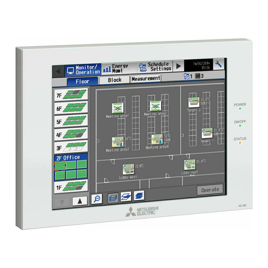
Air Conditioning Control System
Centralized Controller
AE-200A/AE-50A
AE-200E/AE-50E
Before using the controller, please read this Instruction Book carefully to ensure proper operation.
Retain this manual for future reference.
Contents
1. Safety precautions ..............................................................4
1-1. General precautions ...................................................................4
1-2. Precautions for relocating or repairing the unit ...........................5
1-3. Additional precautions .................................................................5
2. Introduction .........................................................................6
2-1. Terms used in this manual ..........................................................6
2-2. Required licenses .......................................................................6
2-3. About this manual .......................................................................6
3. Basic operations .................................................................7
3-1. Monitor/Operation .......................................................................7
3-2. Energy Management ................................................................21
3-3. Schedule ...................................................................................24
3-4. Status List .................................................................................44
3-5. Malfunction Log ........................................................................48
4. Practical operations ..........................................................50
4-1. Cleaning the touch panel ..........................................................50
5. Initial startup settings ........................................................51
5-1. Initial startup setting procedures ...............................................51
5-2. Initial Settings ...........................................................................56
Control Web ..............................................................................80
6. Maintenance .....................................................................84
6-1. Backing up settings data ...........................................................84
6-2. Importing settings data .............................................................85
6-3. Software Update .......................................................................86
6-4. Software information .................................................................88
7. Specifications ....................................................................89
Instruction Book
Advertisement
Table of Contents

Related Manuals for Mitsubishi Electric AE-200A


Summary of Contents for Mitsubishi Electric AE-200A
-
Page 1: Table Of Contents
Air Conditioning Control System Centralized Controller AE-200A/AE-50A AE-200E/AE-50E Instruction Book Contents 1. Safety precautions ..............4 1-1. General precautions ..............4 1-2. Precautions for relocating or repairing the unit ......5 1-3. Additional precautions ..............5 2. Introduction .................6 2-1. Terms used in this manual ............6 2-2. - Page 2 Contents 1. Safety precautions ....................4 1-1. General precautions ....................4 1-2. Precautions for relocating or repairing the unit ............5 1-3. Additional precautions ..................... 5 2. Introduction ......................6 2-1. Terms used in this manual ..................6 2-2. Required licenses ....................6 2-3.
- Page 3 5-2-5. Unit Information ..................62 5-2-6. Network ...................... 66 5-2-7. Groups ......................70 5-2-8. Blocks ......................72 5-2-9. Floor Layout....................73 5-2-10. System View ..................... 78 5-2-11. Floor Layout settings on the Integrated Centralized Control Web .... 79 5-3. Environment settings for Integrated Centralized Control Web ......80 5-3-1.
-
Page 4: Safety Precautions
1. Safety precautions ►Observe these precautions carefully to ensure safety. ►After reading this manual, pass the manual on to the end user to retain for future reference. ►The user should keep this manual for future reference and refer to it as necessary. This manual should be made available to those who repair or relocate the units. -
Page 5: Precautions For Relocating Or Repairing The Unit
Consult your dealer for the proper disposal of the controller. Improper disposal will pose a risk of environmental pollution. 1-2. Precautions for relocating or repairing the unit The controller must be repaired or moved only by qualified personnel. Do not disassemble or modify the controller. -
Page 6: Introduction
Peak Cut control can be performed without a use of a PI controller (PAC-YG60MCA). Each AE-200A/AE-50A/AE-200E/AE-50E can control up to a total of 50 indoor units and other equipment. By connecting AE-200A/AE-200E (main controller) and AE-50A/AE-50E/EW-50A/EW-50E (sub controllers), up to 200 indoor units and other equipment can be controlled. -
Page 7: Basic Operations
3. Basic operations 3-1. Monitor/Operation Unit groups can be monitored and operated on the AE-200/AE-50’s LCD or the Integrated Centralized Control Web. This section explains how to monitor and operate the unit groups. 3-1-1. Screen sequence 3-1-1-1. LCD [Floor] display (zoomed-in) [Floor] display (zoomed-out) Touch [ Touch [... - Page 8 3-1-1-2. Integrated Centralized Control Web Home Home (preview) Floor Layout (simple operation) Floor Layout Advanced settings Group list Group list (simple operation) Measurement status WT07982X03...
-
Page 9: Group Icons
3-1-2. Group icons Each group icon indicates the operation condition of the group. Touch the icon, and then touch [Operate] to bring up the operation settings screen. Air conditioning unit group Error Schedule set Note: Refer to the Instruction Book (Detailed operations) or Instruction Book (Integrated Centralized Control Web) for details and other icons. - Page 10 Item Description Floor selection Select a floor you want to monitor. Area selection Select an area of the selected floor you want to monitor. Group name The name of the group will appear. Room temperature Indoor unit return air temperature will appear. Room humidity The room humidity will appear.
- Page 11 3-1-3-2. Integrated Centralized Control Web [1] Group display Click [Monitor/Operation] in the menu, and then click [Show groups] to display the operation status of unit groups. Show groups Controller Select all Deselect all Number of units Group icon currently in error Item Description Click to narrow down the unit groups to display into “Centralized controller units,”...
- Page 12 [2] Floor Layout display Click [Monitor/Operation] in the menu, and then click [Floor Layout] or “Floor display area” to display the operation status of unit groups on the floor layout. The floor layout to be displayed can be changed by clicking “Floor display area”...
-
Page 13: Selecting The Icons Of The Groups To Be Operated
3-1-4. Selecting the icons of the groups to be operated On the [Floor] or [Block] display under the [Monitor/Operation] menu, select the icon(s) of the group(s) to be operated as explained below, and then touch [Operate] (click [Advanced] on the Integrated Centralized Control Web) to bring up the operation settings screen. - Page 14 (3) Selecting all groups on all floors On the [Floor] or [Block] display, touch the “Select-all- groups” button. All floor and group icons will appear with an orange frame. To cancel all group selections, touch the “Deselect-all” button. Select-all-groups Deselect-all (4) Selecting all groups in the selected block On the [Block] display, touch the block(s) you want to Block icon...
- Page 15 3-1-4-2. Integrated Centralized Control Web [1] Selecting group icons (1) Selecting unit group(s) (1) In the Floor Layout screen or group list, click the icon(s) of the group(s) you want to operate. The selected group icon(s) will appear with a checkmark and a dark blue frame. Click again to deselect.
- Page 16 (3) Selecting all groups (1) In the group list, click [Select all]. The all icon(s) will appear with a checkmark and a dark blue frame. To cancel all group selections, click [Deselect all] or [Close] in the taskbar. Group list Select all Deselect all Close...
- Page 17 (6) Selecting all groups in the entire building (1) In the Home screen, click [Entire building]. To cancel all group selections, click [Close] in the taskbar. Close Entire building WT07982X03...
- Page 18 [2] Selecting equipment type (1) When the equipment types of all selected groups are the same Selecting the group icons to operate and clicking [Advanced] in the taskbar will bring up the operation settings screen for the selected groups. Refer to section 3-1-5 “Operation settings screen” for details about the advanced settings. Selecting groups of the same equipment type...
-
Page 19: Operation Settings Screen
Filter Sign Touch to go to the previous page. Note: The Setback mode can be selected on the AE-200A/AE-50A, but not on the AE-200E/AE-50E. Note: The Hold function can be used on the AE-200A/AE-50A, but not on the AE-200E/AE-50E. WT07982X03... - Page 20 Click to reset the screen without making any filter sign. changes. Note: The Setback mode can be selected on the AE-200A/AE-50A, but not on the AE-200E/AE-50E. Note: The Hold function can be used on the AE-200A/AE-50A, but not on the AE-200E/AE-50E. WT07982X03...
-
Page 21: Energy Management
3-2. Energy Management Only the outline of energy management function is given in this manual. For details on how to use the function, refer to the AE-200/AE-50 Instruction Book (Detailed operations) or the AE-200/AE-50/EW-50 Instruction Book (Integrated Centralized Control Web). 3-2-1. -
Page 22: Ranking
3-2-2. Ranking On the Ranking screen, the rankings in electric energy consumption, fan operation time, and Thermo-ON time (Total/ Cool/Heat) of given indoor units can be displayed per block, group, and unit address in descending order in the bar graph. 3-2-2-1. -
Page 23: Target Value
3-2-3. Target value This section explains how to set the target electric energy consumption values for the entire system for the current year, each month, each day of the week, and each block. 3-2-3-1. LCD 3-2-3-2. Integrated Centralized Control Web Note: Target values can only be displayed on the Integrated Centralized Control Web. -
Page 24: Schedule
3-3. Schedule Weekly (5 types), annual (5 types), and current day scheduling are available. Schedules can be set for each group, each floor, each block, or all groups. Important ● When one or more AE-50/EW-50 controllers are connected, the schedule settings must be made with the AE-50/EW-50 properly connected to ensure proper settings. - Page 25 Note: When the schedules overlap, schedule with the highest priority will run as shown below. Priority High Today’s schedule Schedules can be set for the current day without modifying the weekly or annual schedules. Annual schedule Different schedules can be set for public holidays or summer vacation.
-
Page 26: Weekly Schedule
3-3-1. Weekly Schedule Schedules can be set for each day of the week. Note: When today’s schedule and weekly schedule are set for the same day, today’s schedule settings take precedence over weekly schedule settings. Note: When the “Schedule: Season setting” setting is set to [Available] (default setting), weekly schedule date range settings can be configured. - Page 27 (2) If different equipment types exist together, a screen to select an equipment type will appear. Touch one of the equipment types to set the schedule. (3) A [Schedule Settings] screen will appear. To create a schedule for the given block from scratch, touch [New settings] and touch [OK].
- Page 28 [4] Setting the contents of the schedule (1) Touch the row of the schedule to be set in the “Contents of Schedule” section to display the schedule settings screen. Set the start time to apply to the schedule, set the operations to be scheduled, and then touch [OK]. Note: If [Optimized Start] is selected, the operation mode and the set temperature need to be set as well.
- Page 29 [5] Copying a schedule to another day of the week (1) To copy the schedule settings of a day to the schedule Day of the week selection settings for another day of the week, select the day Paste whose schedule settings are to be copied, touch [Copy], Copy select the day to which the copied schedule settings are to be pasted, and touch [Paste].
- Page 30 3-3-1-2. Integrated Centralized Control Web [1] Selecting a target to which the schedule will be applied In the Floor Layout screen or group list, select a group icon(s) to which the schedule will be applied, and click [Schedule settings]. A screen to set a schedule for the selected group(s) will appear. Refer to section 3-1-4 “Selecting the icons of the groups to be operated”...
- Page 31 [2] Setting the date range for each schedule Five types of weekly schedules can be set. (One year is divided into the maximum of five periods.) Note: This setting is “Season Settings” on the LCD. Note: The weekly schedule date ranges are set for each centralized controller (AE-200/AE-50/EW-50). When the weekly schedule date ranges are set with Integrated Centralized Control Web, the same settings will be sent to all the centralized controllers that are control targets of Integrated Centralized Control Web.
- Page 32 [3] Selecting a day of the week Schedules can be set for each day of the week for each weekly schedule (Weekly 1 to 5). (1) In the Schedule settings screen, select one of the weekly schedule (Weekly 1 to 5). (2) Click the day to set the schedule.
- Page 33 (2) In the schedule contents settings screen, set the start time to apply to the schedule, set the operations to be scheduled, and then click [OK]. If [Optimized Start] is selected, the operation mode and the set temperature need to be set as well. Schedule contents settings (1/2) Schedule contents settings (2/2) Scheduled...
- Page 34 [5] Saving the schedules (1) After the schedule settings are completed, click [Send] on the Schedule settings screen to send and save the settings to the centralized controllers. To undo the changes made, click [Cancel]. Schedule settings Cancel Send Click to save the settings. Click to undo the changes made and close the Schedule settings screen.
- Page 35 • Group list Procedure (1) Procedure (3) Procedure (2) Group icon Copy Name of the group Copied Group icon Select the group Click to copy the whose schedule The group icon Select the group whose schedule schedule contents of settings are copied will appear to which the settings are to be...
-
Page 36: Annual Schedule
3-3-2. Annual Schedule On the Annual Schedule settings screen, schedules can be set for public holidays or summer vacation. Up to five operation patterns (Pattern A through E) can be set for the 24 months including the current month, and total of 50 days can be allocated to the patterns. - Page 37 [3] Setting the contents of the schedule (1) Touch the row of the schedule to be set in the “Contents of Schedule” section to display the schedule settings screen. Set the start time to apply to the schedule, set the operations to be scheduled, and then touch [OK]. (Refer to section 3-3-1-1 [4] “Setting the contents of the schedule”...
- Page 38 [6] Saving the schedules (1) To undo the changes made, touch [Cancel] before saving the schedules. After completing the settings, touch [OK] to save the schedules. Cancel [7] Copying a schedule to another group (1) Refer to 3-3-1-1 [7] “Copying a schedule to another group” for details. WT07982X03...
- Page 39 3-3-2-2. Integrated Centralized Control Web [1] Selecting a target to which the schedule will be applied (1) In the Floor Layout screen or group list, select a group icon(s) to which the schedule will be applied. Refer to 3-3-1-2 [1] “Selecting a target to which the schedule will be applied” for details. [2] Selecting a schedule pattern Up to five operation patterns can be set.
- Page 40 [4] Allocating schedule patterns to special dates Each schedule pattern can be allocated to the specified dates such as public holidays and summer vacation. (1) In the Schedule settings screen (Month or Week display), click the date to set a pattern. (2) Select the pattern to be allocated to the selected date.
- Page 41 [7] Creating a schedule based on existing settings of other pattern When setting annual schedule patterns, the schedule settings can be created based on existing settings of other pattern. (1) In the Edit schedule settings screen, click [Based on...]. (2) In the [Based on...] screen, select the pattern or the day of the week whose schedule is to be based on. (3) The contents of the schedule that have been set for the selected pattern or the day of the week will appear in the Edit schedule settings screen.
-
Page 42: Today's Schedule
3-3-3. Today’s Schedule On the Today’s Schedule settings screen, schedules can be set for the current day without modifying the weekly or annual schedules. Note: Be sure to set the contents of schedule in a way that will not impact on the next day’s operation. For example, if Prohibit setting of remote controller operation is made for any time such as 17: 00, Permit setting needs to be made for any time before the date changes such as 23: 59. - Page 43 3-3-3-2. Integrated Centralized Control Web [1] Selecting a target to which the schedule will be applied (1) In the Floor Layout screen or group list, select a group icon(s) to which the schedule will be applied. Refer to 3-3-1-2 [1] “Selecting a target to which the schedule will be applied” for details. [2] Setting or changing the contents of the schedule (1) In the Schedule settings screen (Month or Week display), click the date of the current day.
-
Page 44: Status List
3-4. Status List 3-4-1. Malfunction List 3-4-1-1. LCD Touch [Status List] in the menu bar, and then touch [Malfunction]. A list of units that are currently malfunctioning will appear. Note: The [Controller] setting will appear (only on the AE-200’s LCD) when the [System Exp] setting on the [Unit Info.] screen is set to [Expand]. - Page 45 3-4-1-2. Integrated Centralized Control Web Click [Notice] in the menu, and then click [Error List] to access the Error List screen. A list of units that are currently malfunctioning will appear. Note: When an error occurs, check the address of the unit in error, error code and its definition, and then contact your dealer. Reset All Controller Group name...
-
Page 46: Filter Sign List
3-4-2. Filter Sign List 3-4-2-1. LCD A list of units whose filter sign is turned on can be displayed. Touch [Status List] in the menu bar, and then touch [Filter Sign]. Note: The [Controller] setting will appear (only on the AE-200’s LCD) when the [System Exp] setting on the [Unit Info.] screen is set to [Expand]. - Page 47 3-4-2-2. Integrated Centralized Control Web A list of units whose filter sign is turned on can be displayed. Click [Notice] in the menu, and then click [Filter sign] to access the Filter sign screen. Reset All Group name Controller Reset Unit address Item Description...
-
Page 48: Malfunction Log
3-5. Malfunction Log 3-5-1. Unit Error/Communication Error 3-5-1-1. LCD Touch [Log] in the menu bar, and then touch [Unit Error] to display unit errors, or touch [Communication Error] to display M-NET communication errors. Note: The [Controller] setting will appear (only on the AE-200’s LCD) when the [System Exp] setting on the [Unit Info.] screen is set to [Expand]. - Page 49 3-5-1-2. Integrated Centralized Control Web Click [Notice] in the menu, and then click [Unit error log] to access the Unit error log screen. Note: The latest 64 unit errors will appear for each AE-200/AE-50/EW-50. Note: Unit errors of all AE-200/AE-50/EW-50 controllers will appear in a list. Clear log Controller Group name...
-
Page 50: Practical Operations
4. Practical operations 4-1. Cleaning the touch panel (1) Touch [ ] to display the login window. (2) On the Login window, touch the “Touch-panel-cleaning” button. Touch-panel-cleaning (3) Clean the touch panel with a soft dry cloth, a well-wrung cloth that has been soaked in water with mild detergent, or a cloth dampened with ethanol. -
Page 51: Initial Startup Settings
5. Initial startup settings 5-1. Initial startup setting procedures 5-1-1. AE-200 initial start-up for a system without connection to an AE-50/EW-50 controller (1) After the power is turned on, a language selection screen will appear. Select the language to be used for display, and then touch [OK]. Note: It will take approximately one minute for the display to appear after the power is turned on. -
Page 52: Ae-50/Ew-50 Controller
(4) Touch the right triangle button to display the [Groups] tab, and touch it. Referring to section 5-2-7, make group settings, and then touch [Save Settings]. (5) Make the following settings, as required. ● Block settings (See section 5-2-8 “Blocks”.) ●... -
Page 53: Ae-200 Initial Start Up For A System With Connection To One Or More
5-1-2. AE-200 initial start up for a system with connection to one or more AE-50/EW-50 controllers Note: When connecting one or more AE-50/EW-50 controllers, make sure to make network settings for the AE-50/EW-50 first, and then make network settings for the AE-200. [1] Settings on the AE-50 (1) After the power is turned on to the AE-50, a language selection screen will appear. - Page 54 (2) Touch the [Unit Info.] and [Unit Info. 2] tabs. Unit Info. Referring to section 5-2-5, make necessary basic settings, and then touch [Save Settings]. Note: Make sure to set the [System Exp] setting for the AE-200 to [Expand]. Note: The [AE-200 Apportion] setting will appear only when the “Charge”...
- Page 55 (5) Touch the [Groups] tab. Referring to section 5-2-7, select [AE], [1], [2], [3], or [4] in the [Controller] section, make group settings for each AE-200/AE-50/EW-50, and then touch [Save Settings] on each settings screen. A message “Collecting connected equipment status data. Please wait...”...
-
Page 56: Initial Settings
5-2. Initial Settings 5-2-1. Logging in to the Initial Settings menu (1) Touch [ ] to display the login window. (2) Enter the user name and the password on the keyboard screen (See [1] “Keyboard screen”), and touch [Login]. [Initial Settings] menu screen will appear. The table below shows the default user names, passwords, and functions that are available for maintenance users and building managers. - Page 57 [1] Keyboard screen Arrow The entered characters will appear here. Touch to move the cursor. Delete Touch to delete one character to the left of the cursor. Touch to display the keyboard for entering capital Cancel alphabetic characters. Touch to undo the changes made and return to the previous screen.
-
Page 58: Locking The Screen
5-2-2. Locking the screen Locking the screen prevents unauthorized users from accessing. (1) To activate the screen lock function, set the [Screen lock] setting to [Use] on the [Unit Info.] screen under the [Initial Settings] menu. If the screen lock function is activated, the screen locks when the backlight turns off (after three minutes of not touching the screen). -
Page 59: Date And Time
5-2-3. Date and time Touch [Initial Settings] in the menu bar, and then touch [Date and time]. Set the current date and time, and then touch [Save Settings]. Note: The date and time settings may not be accessible if logged in as a building manager. Note: The date and time settings made on this screen will be reflected on all the units in the M-NET system, all connected AE-50/EW-50 units, and the AE-200 units whose [Time Master/Sub] setting is set to [Sub]. - Page 60 Note ● Message that will appear when the date and time have been reset If the power supply is cut off for a long time due to power failure or other reasons, the date and time will be reset, and the following popup message will appear when the power is turned on next.
-
Page 61: License Registration For Optional Functions
5-2-4. License registration for optional functions Touch [Initial Settings] in the menu bar, and then touch [License]. Please ask your dealer for more details on the optional functions and how to purchase a license number. Note: The current date and time settings are required for license registration. Refer to section 5-2-3 “Date and time” for date and time settings. -
Page 62: Unit Information
5-2-5. Unit Information Touch [Initial Settings] in the menu bar, and then touch [Unit Info.] or [Unit Info. 2]. Make necessary basic system settings such as unit settings, display format, sound/brightness settings, use or non- use of test run, and display or non-display of room temperature/humidity, and then touch [Save Settings]. Note: The Unit Information settings may not be accessible if logged in as a building manager. - Page 63 (2) Touch the [Unit ID] button to display the keyboard. Enter the unit ID in 6 figures. Use this setting to manage the multiple unit IDs. The unit ID entered here will be used on the screen of the software that controls multiple AE-200 units and will also be used as a sender ID in the error notification e-mail and e-mail alarm.
- Page 64 (8) In the [Brightness] section, make the Show/Hide setting for the brightness/darkness status that is detected by the built-in brightness sensor on the ME remote controller (North America: PAR-U01MEDU, Europe: PAR- U02MEDA). Select [Hide] not to display the brightness/darkness icons on the [Floor] or [Block] display. Select [ ] (yellow) to display the brightness icon when the brightness level in the room reaches the predetermined brightness level.
- Page 65 (2) In the [Room temperature] section, select the desired temperature display option to be used on the [Floor] or [Block] display. Select [Always show] to display the temperature at all times, [Show during operation] to display the temperature only during operation, and [Hide] not to display the temperature. Note: This setting is effective only on the LCD and will not be reflected to the Web browser.
-
Page 66: Network
5-2-6. Network Touch [Initial Settings] in the menu bar, and then touch [Network]. Make necessary basic system settings such as LAN settings, M-NET settings, and external input settings for each AE-200, AE-50, and EW-50, and then touch [Save Settings]. A message will appear asking whether or not to restart the controller. - Page 67 Only when an AE-50/EW-50 is connected By using a communication error detection function, communication errors between AE-200/AE-50/EW-50 can be displayed on the AE-50’s LCD via AE-200. Detect communication error IP address of AE-200 Select whether “Detect” or “Do not detect” communication error for each IP address.
- Page 68 (4) When monitoring the system remotely or using e-mail function via a dial-up router, enter the router IP address in the [Gateway] field. Leave the [Gateway] field blank when not connecting a dial-up router. [192.168.1.254] is recommended for use as the IP address of the dial-up router. Refer to the dial-up router instruction manual for details of how to set the IP address.
- Page 69 [3] M-NET Settings Note: Make the M-NET settings only on the AE-200. (1) Switch the [Controller] setting between [AE200] and [Exp1] through [Exp4] to make settings for each AE-200, AE-50, and EW-50 individually. (2) Enter [0] in the [M-NET Address] field (unless otherwise specified). (3) Select [SC/RC] to prohibit the operation from both the sub system controllers and the remote controllers.
-
Page 70: Groups
5-2-7. Groups Touch [Initial Settings] in the menu bar, and then touch [Groups]. Register the groups of air conditioning units to be connected to the AE-200/AE-50/EW-50, and then touch [Save Settings]. Note: Some settings may not be accessible if logged in as a building manager. Note: If the system is connected to a TG-2000A, make or change the settings from the TG-2000A. - Page 71 [2] Registering air conditioners to a group (1) To register air conditioners to each group, touch the “Unit selection” button under the target group name. A screen to select the units will appear. Select the group type in the [Model] section, and select the address numbers of the units to be registered.
-
Page 72: Blocks
5-2-8. Blocks By making block settings, multiple groups in a given block can be collectively monitored or operated. Touch [Initial Settings] in the menu bar, and then touch [Blocks]. Register the groups to each block, and then touch [Save Settings]. Note: Some settings may not be accessible if logged in as a building manager. -
Page 73: Floor Layout
5-2-9. Floor Layout The floor layout on the [Floor] display under the [Monitor/Operation] menu can be changed, and the display position of the groups on the floor can be changed. Touch [Initial Settings] in the menu bar, and then touch [Floor Layout]. All unit groups that are under the control of both AE-200 and AE-50 can be displayed on the Floor Layout screen of the AE-200. - Page 74 The display range of the area on the [Floor Layout] screen vary, depending on the selected floor layout. Floor layout Display area Floor layout Display area (3) Touch the “Floor level name” button to display the Floor level name keyboard. Enter the floor level name in 3 alphanumeric Floor name or symbol characters or less.
- Page 75 Available colors (RGB) to be used in the file * Use the colors in the table above, otherwise the floor plan will appear in different colors. * The default background color is RGB [103, 103, 103]. WT07982X03...
- Page 76 [3] Moving a group to other areas (1) On the [Floor Layout] screen, touch the group icon to be moved. The selected group icon will appear with an orange frame. Note: When the “Unassigned groups” button is touched, groups that have not been assigned to any area will appear in the order of their group numbers.
- Page 77 (4) Touch [Save Settings]. Note: To move the pasted group icon within the area, refer to [4] “Moving a group within the area” below. [4] Moving a group within the area Note: It is recommended to use a commercially available touch pen. (1) On the [Floor Layout] screen, touch the group icon to be moved.
-
Page 78: System View
5-2-10. System View Refrigerant system information (connection information of outdoor and indoor units) can be checked for each AE-200, AE-50, and EW-50. Touch [Initial Settings] in the menu bar, and then touch [System View]. Note: This screen shows the information of the units that have been registered to a group and have started up successfully. Note: The [Controller] setting will appear (only on the AE-200’s LCD) when the [System Exp] setting on the [Unit Info.] screen is set to [Expand]. -
Page 79: Floor Layout Settings On The Integrated Centralized Control Web
5-2-11. Floor Layout settings on the Integrated Centralized Control Web [1] Matching the floor layout on the AE-200’s LCD and the Integrated Centralized Control Web On the Integrated Centralized Control Web, a setting can be made to use the same layout as the one used on the LCD. -
Page 80: Environment Settings For Integrated Centralized Control Web
5-3. Environment settings for Integrated Centralized Control Web 5-3-1. Operating environment The following table shows the supported operating systems and browsers for using this Integrated Centralized Control Web with PCs. Item Requirement 1 GHz or faster (2 GHz or faster recommended) Memory 2 GB or more Screen resolution... -
Page 81: System Settings
5-3-2. System Settings To use Integrated Centralized Control Web, you need to configure the settings using Initial Setting Tool. Refer to the AE-200/AE-50/EW-50 Instruction Book (Initial Settings) for details. Important ● When using Initial Setting Tool, be sure to configure the settings as described in the procedures of Instruction Book (Initial Settings). -
Page 82: Setting The Ip Address Of The Pc
5-3-3. Setting the IP address of the PC Follow the instructions below to set the PC’s IP address to connect the Integrated Centralized Control Web and multiple centralized controllers. The PC’s IP address must have the same network address as the AE-200/AE-50/EW-50’s IP address. (1) Click [Control Panel] in the Start menu. -
Page 83: Logging In To The Integrated Centralized Control Web
5-3-4. Logging in to the Integrated Centralized Control Web (1) Enter the web page address in the address field of the Web browser as follows: http://[IP address of AE-200/EW-50]/control/index.html (2) A login screen will appear. Note: If the IP address of the AE-200/EW-50 is [192.168.1.1], the web page address is [http: //192.168.1.1/control/index.html]. Note: Default IP address of AE-200/EW-50 is [192.168.1.1]. -
Page 84: Maintenance
6. Maintenance 6-1. Backing up settings data The settings data can be exported to a USB memory as a backup. Touch [Maintenance] in the menu bar, and then touch [Backup]. Note: Use the USB memory device that meets the requirements described in 7 “Specifications”. Note: IP address settings will not be backed up. -
Page 85: Importing Settings Data
6-2. Importing settings data The exported data can be imported back to the AE-200/AE-50/EW-50 to restore the previous settings after the controller replacement. Touch [Maintenance] in the menu bar, and then touch [Import]. All settings Read from USB Memory Touch to import the settings data. -
Page 86: Software Update
6-3. Software Update The AE-200/AE-50/EW-50 software can be updated by either directly reading the update file in a USB memory device or by using a Web browser. ① Directly reading the update file in a USB ② Using a Web browser memory device PC for update This manual explains how to update the software by directly reading the update file in a USB memory device ( ①... -
Page 87: Update Procedures
6-3-2. Update procedures Note: The software cannot be downgraded to an earlier version. (1) Remove the controller cover, and insert a USB memory device in which the update file is stored to the USB port. Note: Do not remove the USB memory device while the software is being updated. Note: The USB memory device may not be recognized if you insert and remove it within a short time. -
Page 88: Software Information
(7) Touch [ ] to display the login window. Check that the version on the login window is the same as the version of the update file (AExx_FW####_****.dat). 6-4. Software information Detailed information about the open source software of the AE-200/AE-50/EW-50 can be checked by accessing the following address: https://[IP address of each AE-200, AE-50, or EW-50]/license/ * Accessible only if logged in as a maintenance user. -
Page 89: Specifications
7. Specifications Item Specifications Power supply Rated input 100–240 VAC ± 10%; 0.3–0.2 A 50/60 Hz Single-phase No specifications M-NET power feeding coefficient * Only an MN converter can be connected. Operating temperature 0°C – +40°C (+32°F – +104°F) range Temperature Ambient Storage temperature... - Page 90 This equipment has been tested and found to comply with the limits for a Class B digital device, pursuant to Part 15 of the FCC Rules. These limits are designed to provide reasonable protection against harmful interference in a residential installation.
- Page 91 WT07982X03...
- Page 92 This product is designed and intended for use in the residential, commercial and light-industrial environment. The product at hand is based on the following EU regulations: • Low Voltage Directive 2006/95/EC • Electromagnetic Compatibility Directive 2004/108/EC • Restriction of Hazardous Substances 2011/65/EU Please be sure to put the contact address/telephone number on this manual before handing it to the customer.
Need help?
Do you have a question about the AE-200A and is the answer not in the manual?
Questions and answers
Hi, trying to register a new ae200 but won’t accept either passwords administrator or initial, thoughts please