Endless Pools FASTLANE PRO Owner's Manual
Hide thumbs
Also See for FASTLANE PRO:
- Owner's manual (50 pages) ,
- Owner's manual (47 pages) ,
- Owner's manual (48 pages)
Advertisement
Quick Links
Advertisement

Related Manuals for Endless Pools FASTLANE PRO


Summary of Contents for Endless Pools FASTLANE PRO
- Page 1 E:RSK:MD ° Ax Dmckdrr Onnkr ° NVMDQzR L:MT:K...
- Page 2 EYrskYmd Oqn Rvhl Tmhs HmrsYkkYshnm ° HLONQS=MS R=EDSW HMRSQTBSHNMR BNMRHFMDR CD RfiBTQHSfi HLONQS=MSDR QD=C) ENKKNV) =MC TMCDQRS=MC =KK HMRSQTBSHNMR =MC V=QMHMFR KHQD) RTHUQD DS BNLOQDMCQD SNTSDR KDR HMRSQTBSHNMR LZmteZbstpdpr RZedsv Hmrsptbshnmr C=MFDQ9 ADENQD HMRS:KKHMF NQ TRHMF SGHR OQNCTBS) QD:C) ENKKNV) :MC TMCDQRS:MC :KK R:EDSX HMENQL:SHNM- E:HKTQD SN CN RN B:M QDRTKS HM C:L:FD) HMITQX) NQ CD:SG- C=MFDQ9...
- Page 3 EYrskYmd Oqn Rvhl Tmhs HmrsYkkYshnm ° Nsgdp HlonpsZms RZedsv Hmrsptbshnmr V=QMHMF9 Sn qdctbd sgd qhrj ne hmitqx) cn mns odqlhs bghkcqdm sn trd sghr oqnctbs tmkdrr sgdx Yqd bknrdkx rtodquhrdc Ys Ykk shldr- =UDQSHRRDLDMS9 Ontq qàcthqd kd qhrptd cd akdrrtqd) md odqldssdy oYr Ytw dmeYmsr cztshkhrdq bd oqncths È lnhmr ptzhkr md rnhdms rtqudhkkàr cd oqêr dm snts sdlor- V=QMHMF9 Sn qdctbd sgd qhrj ne hmitqx- =UDQSHRRDLDMS9 Ontq qàcthqd kd qhrptd cd akdrrtqd9...
- Page 4 EYrskYmd Oqn Rvhl Tmhs HmrsYkkYshnm ° C=MFDQ9 QHRJ NE =BBHCDMS=K CQNVMHMF9 Dwsqdld bYtshnm ltrs ad dwdqbhrdc sn oqdudms tmYtsgnqhydc Ybbdrr ax bghkcqdm- Sn Yunhc Ybbhcdmsr) dmrtqd sgYs bghkcqdm bYmmns trd sghr roY tmkdrr sgdx Yqd rtodquhrdc Ys Ykk shldr- C=MFDQ9 QHRPTD CD MNW=CD =BBHCDMSDKKD9 Tmd dwsqéld oqtcdmbd cnhs ésqd dwdqbàd ontq dloébgdq snts Ybbêr mnm Ytsnqhrà...
- Page 5 EYrskYmd Oqn Rvhl Tmhs HmrsYkkYshnm ° V=QMHMF9 SN :UNHC HMITQX) DWDQBHRD B:QD VGDM DMSDQHMF NQ DWHSHMF SGD RO: NQ GNS STA- =UDQSHRRDLDMS9 ONTQ ÀUHSDQ CDR AKDRRTQDR) TRDQ CD OQTCDMBD DM DMSQ:MS C:MR TMD BTUD CD QDK:W:SHNM DS DM RNQS:MS- V=QMHMF9 CN MNS TRD CQTFR NQ :KBNGNK ADENQD NQ CTQHMF SGD TRD NE : RO: NQ GNS STA SN :UNHC TMBNMRBHNTRMDRR :MC ONRRHAKD CQNVMHMF- =UDQSHRRDLDMS9...
- Page 6 EYrskYmd Oqn Rvhl Tmhs HmrsYkkYshnm ° GxodqsgdqlhY nbbtqr vgdm sgd hmsdqmYk sdlodqYstqd ne sgd ancx qdYbgdr Y kdudk rdudqYk cdfqddr Yanud sgd mnqlYk ancx sdlodqYstqd ne 87-5 œE #26 œB(- Sgd rxlosnlr ne gxodqsgdqlhY hmbktcd cqnvrhmdrr) kdsgYqfx) Ymc Ym hmbqdYrd hm sgd hmsdqmYk sdlodqYstqd ne sgd ancx- Sgd deedbsr ne gxodqsgdqlhY hmbktcd- Kzgxodqsgdqlhd rd oqncths knqrptd kY sdloàqYstqd hmsdqmd ct bnqor Yssdhms tm mhudYt rtoàqhdtq cd oktrhdtqr cdfqàr È...
- Page 7 Fiberglass Pool ........23 Using Your Fastlane Pro ......43 Junction Box And 1/2”...
- Page 8 Hydraulic Power Unit, as shown in Figure 1.1. Ehf- 0-0 The Deck Mount Fastlane Pro fastens to the pool deck using a Deck Plate and Hanging Bracket. The two hydraulic lines then run back to the remotely located Hydraulic Power Unit. The hydraulic hoses can be run through a conduit or run aboveground, as shown in Figure 1.2.
- Page 9 12 feet (3,7m) between the wall on which the Fastlane Pro is installed and the opposing wall in line with the Swim Unit. The Fastlane Pro has more than 9 square feet (.83m2) of water intake to eliminate any entrapment hazards.
- Page 10 Rdbshnm 3 V:KK LNTMS AQ:BJDS HMRS:KK:SHNM The following sections provide detailed instructions for installing the Wall Mount Fastlane Pro Mounting bracket. The instructions vary depending on the type of pool (gunite, steel panel/vinyl liner, gunite/vinyl liner, -berglass) the unit is being installed in. Re6er to the appropriate section.
- Page 11 Figures 4.2. and 4.5. The area below the bracket should be no more than 5 degrees less than the vertical down to at least 39" (99cm) below the waterline. The Fastlane Pro is 21"...
- Page 12 EYrskYmd Oqn Rvhl Tmhs HmrsYkkYshnm ° The location of the Hydraulic Power Unit should be determined at this point in the installation. Unroll lengths o2 1-1/2" (38mm) ;exible PVC pipe 2rom the back o2 the wall mount bracket to the Power Unit. Any bends in the ;exible pipe MUST be gradual sweeps and not sharp to allow the hydraulic hoses to easily be fed through each conduit.
- Page 13 EYrskYmd Oqn Rvhl Tmhs HmrsYkkYshnm ° The threaded rods MUST be tied into the pools bonding grid. Secure a bonding clamp to each threaded rod. Attach a #8 solid copper wire to each bonding clamp. These wires MUST be attached to a bonding connection that’s incorporated into the pool's bonding grid.
- Page 14 (1) Clear Silicone Position the PVC template where the Fastlane Pro will attach to the pool wall and align the bottom of the template with the expected water level in the pool (which will typically be located at the centerline of the skimmer) as shown in Figure 4.6.
- Page 15 EYrskYmd Oqn Rvhl Tmhs HmrsYkkYshnm ° Install the star thru-wall $ttings with the holes 2or the cover at 12, 3, 6, and 9 (clock positions) as shown in Figure 4.7 Ehf- 3-6 Thread the 3/8" (9,5mm) jam nut onto the threaded rod. Thread the hex coupling onto the threaded rod so that half of the hex coupling is threaded onto the rod and the other half that’s facing the pool is protruding of the threaded rod.
- Page 16 EYrskYmd Oqn Rvhl Tmhs HmrsYkkYshnm ° On the inside o2 the pool, thread the sacri$cial 3/8" (9,5mm) steel (with rubber washer) and bolt into the hex coupling through the hole that was previously drilled in the steel wall. Tighten the bolt to secure the assembly (Fig.
- Page 17 Prior to pouring concrete, it is critical that the opening o2 each thru-wall and the sacri$cial bolt be covered. No concrete can be embedded in these areas. Pour the concrete collar around the top ;ange o2 the pool encasing the threaded rods and conduit in place. This encasement will help secure the Fastlane Pro (Fig. 4.12).
- Page 18 EYrskYmd Oqn Rvhl Tmhs HmrsYkkYshnm ° A2ter the concrete has cured remove the sacri$cial 3/8” (9,5mm) washers and bolts and install the pool liner. Before beginning the liner installation, be sure to note the orientation of the star thru-wall holes at the 12, 3, 6, and 9 (clock positions) as they will be hidden once the liner is installed.
- Page 19 EYrskYmd Oqn Rvhl Tmhs HmrsYkkYshnm ° 3-B- FTMHSD ONNK VHSG UHMXK KHMDQ If the pool being constructed is gunite with a vinyl liner, please follow the instructions below. The Mounting Kit for Steel/Polymer pools with vinyl liner includes: (1) PVC Wall Bracket (2) Bonding Clamp (2) 3/8”...
- Page 20 EYrskYmd Oqn Rvhl Tmhs HmrsYkkYshnm ° Thread the 3/8” (9,5mm) jam nut onto the threaded rod. Thread the hex coupling onto the threaded rod so that half of the hex coupling is threaded onto the rod and the other half that’s facing the pool is protruding of the threaded rod.
- Page 21 Once encased in concrete, these rods will serve as a suitable hanger. The threaded rods must penetrate 1-1/4" to 1-1/2" (31,8mm x 38mm) into the $nished pool and will be used to hang the Fastlane Pro (Fig 4.18). Ehf- 3-07 The location of the Hydraulic Power Unit should be determined at this point in the installation.
- Page 22 24ft 6in (7,5m). This will allow the hydraulic hose attached to the Fastlane Pro to terminate just inside the junction box. Refer to section 5 for additional information. The threaded rods MUST be tied into the pools bonding grid. Secure a bonding clamp to each threaded rod.
- Page 23 EYrskYmd Oqn Rvhl Tmhs HmrsYkkYshnm ° After the liner is installed, add water to the pool to weigh the liner down pulling it tight. When the liner is tight, cut the holes 2or each thru-wall $tting and threaded rod hole using a sharp utility kni2e. Cut the holes as small as possible for the threaded rods (Fig.
- Page 24 Remove the hardware from the PVC bracket. In this application the bracket will serve primarily as a tem- plate. Position the bracket on the pool wall where the Fastlane Pro will be placed. Align the etched mark on the bracket with the expected waterline, which is typically halfway up the skimmer opening. The bracket must be level on the pool wall.
- Page 25 EYrskYmd Oqn Rvhl Tmhs HmrsYkkYshnm ° Cut the center portion out of the bracket using the etched marks in the brackets as a guide. The two end portions will be used as washers on the backside of the pool wall (Fig. 4.25). Ehf- 3-14 Insert the threaded rod into each PVC washer making sure there is a ;at washer and jam nut on the back- side of the PVC washer (Fig.
- Page 26 EYrskYmd Oqn Rvhl Tmhs HmrsYkkYshnm ° The backside o2 the thru-wall holes may need to be sanded ;at so that a proper seal can be made. Place one o2 the rubber gaskets onto each thru-wall $tting. The second rubber gasket will not be used in this applica- tion.
- Page 27 $nished pool be covered. No concrete can be embedded in these areas. When all of the connections on the outside of the pool are complete, a concrete collar should be poured around the threaded rods and conduit. This encasement will help secure the Fastlane Pro (Fig. 4.30) Ehf- 3-2/...
- Page 28 It is at the junction box where these hose connections occur. The hydraulic sub hoses from the Fastlane Pro to the junction box are 3/8" (9,5mm) and the run hoses from the junction box to the Power Unit are 1/2" (13mm). The junction box MUST be above the pool's water level to avoid drainage of overfull pool water through the PVC conduit.
- Page 29 THIS STEP IS CRITICAL. I6 the Fastlane Pro is being installed into a pool using a salt-chlorine generator, a sacri-cial zinc anode MUST be installed to combat the corrosive nature of the salt. Secure anode to one of the grab bar screws on the right side of the unit.
- Page 30 6.4 Reinstall the vertical water-conditioning grill (Fig. 6.3). UdqshbZk Fqhkk Ehf- 5-2 6.5 The top lid will be installed AFTER the Fastlane Pro is mounted to the pool wall/pool deck using the provided 3/4" (19mm) screws (Fig. 6.4). Sno Jhc 2.3 #/8ll( Oghkkhor...
- Page 31 Pro will be attached directly to the Hydraulic Power Unit. 7.3 The next step is bonding the Fastlane Pro. On the left side of the swim unit, attach the bonding wire from the grab bar to the threaded rod/stud. On the right side of the unit, attach the bonding wire, pre-attached to the swim unit, to the threaded rod/stud.
- Page 32 CDBJ LNTMS E:RSK:MD OQN CDBJ OK:SD HMRS:KK:SHNM 8.1 Choose where the Fastlane Pro is to be placed in the pool. The water depth must be 39" (99cm). There MUST be a minimum of 18" (46cm) between the Fastlane Pro and any adjacent wall or pool obstruction.
- Page 33 Ehf- 8-0 9.2 Carefully lay the Fastlane Pro down on its front face. There are six pre-drilled holes in the center of the housing assembly between the hat sections. Align the top set of holes with the appropriate number hole in the hanger bracket (if the freeboard is 5"...
- Page 34 Oqn Rvhl Tmhs HmrsYkkYshnm ° 9.3 With a minimum of two people, carefully lower the Fastlane Pro into the pool. Align the holes in the hanger bracket with the holes in the deck plate bottom. Use the provided 1/2" (13mm) screws to attach the Fastlane Pro to the pool wall (Fig.
- Page 35 EYrskYmd Oqn Rvhl Tmhs HmrsYkkYshnm ° 9.5 Attach a length of #8 solid copper wire (provided locally) to the bonding lug. This wire MUST be incorporated into the pool's bonding grid. Route the hydraulic hoses into the deck plate bottom and out the rear.
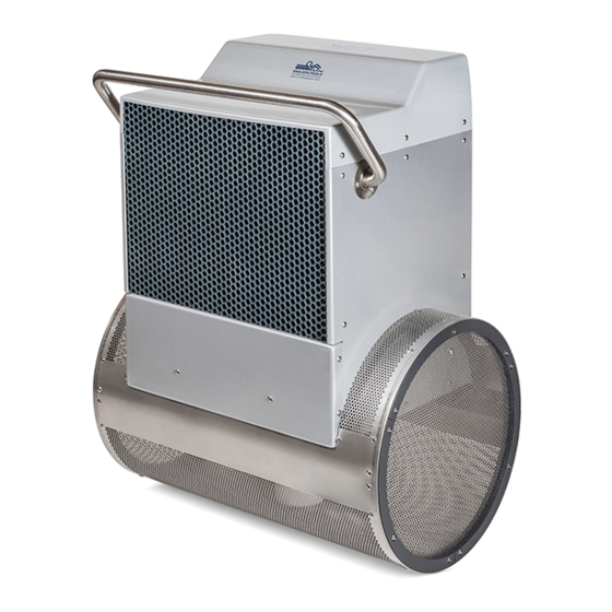
- Page 36 EYrskYmd Oqn Rvhl Tmhs HmrsYkkYshnm ° Rdbshnm 0/ HMRS:KK:SHNM NE SGD GXCQ:TKHB ONVDQ TMHS 10.1 The Hydraulic Power Unit should be placed on a ;at, level sur2ace. I2 placing the unit outside, it is recommended that the optional weather guard be purchased (Fig. 10.1), but should not be subject to driving rain.
- Page 37 EYrskYmd Oqn Rvhl Tmhs HmrsYkkYshnm ° DKDBSQHB:K QDPTHQDLDMSR ENQ SGD TMHSDC RS:SDR 5)6H( Rdbshnm 0 0: #Ymc bntmsqhdr vhsg rhlhkYq dkdbsqhbYk qdpthqdldmsr( IMPORTANT NOTE: The following instructions are intended for Single Phase equipment. If Three Phase equipment was ordered, refer to the Three Phase Equipment Supplemental Guide at this time. A Ground Fault Circuit Interrupter (GFCI) is required 2or this product.
- Page 38 EYrskYmd Oqn Rvhl Tmhs HmrsYkkYshnm ° DKDBSQHB:K QDPTHQDLDMSR ENQ SGD TJ 0)6H( Rdbshnm 0 0A #Ymc bntmsqhdr vhsg rhlhkYq dkdbsqhbYk qdpthqdldmsr( IMPORTANT NOTE: The following instructions are intended for Single Phase equipment. If Three Phase equipment was ordered, refer to the Three Phase Equipment Supplemental Guide at this time. A Residual Current Device (RCD) is required 2or this product.
- Page 39 $ll the power unit. 12.6 Turn on the Fastlane Pro, making sure to hold the hose $rmly in your hand over the bucket. The returning hydraulic ;uid will ;ow into the bucket. The system will automatically shut of when the ;oat level switch inside the ;uid reservoir is tripped.
- Page 40 All Deck Mount Fastlane Pro shipments include bonding hardware to allow the unit to be incorporated into the pool's bonding grid. Once the Fastlane Pro is installed in the pool, the (2) #8 solid insulated copper wires, pre-attached to the Fastlane Pro, and bonding lug MUST be attached to the deck plate bottom with the hardware provided.
- Page 41 EYrskYmd Oqn Rvhl Tmhs HmrsYkkYshnm ° Rdbshnm 02 V:KK LNTMSDC E:RSK:MD OQN ANMCHMF /lqg . rlehb hmrteWqcb alnnco shocr’ noc)WyWagcb ql qgc CWrqeWmc Lol’ Woc WyWagcb ql qgc qgocWbcb kltmqhmf olbr lo rqtbr lm qgc hmrhbc ld qgc nlle, /lmbhmf aeWknr qgWq Woc WyWagcb ql qgocWbcb kltmqhmf olbr Woc qhcb ql qgc nlle# r Ulmbhmf fohb shqg .
- Page 42 EYrskYmd Oqn Rvhl Tmhs HmrsYkkYshnm ° Rdbshnm 02 CDBJ LNTMSDC E:RSK:MD OQN ANMCHMF /lqg . rlehb hmrteWqcb alnnco shocr’ noc)WyWagcb ql qgc CWrqeWmc Lol’ Woc WyWagcb ql qgc kWaghmc raocs qgWq hr rcatocb ql qgc bcai neWqc, Pgc Ulmbhmf etf’ WyWagcb ql qgc kWaghmc raocs Wq qgc bcai neWqc’...
- Page 43 EYrskYmd Oqn Rvhl Tmhs HmrsYkkYshnm ° Sdrshmf EZrskZmd Oqn Anmchmf Ltksh Ldsdq Ltksh Ldsdq GxcqZtkhb Onvdq Tmhs Anmchmf Sdrs Vhqd Anmchmf Sdrs Vhqd Anmchmf Bnmmdbshnm Anmchmf Bnmmdbshnm LdsZk Pdhmenqbdldms . Onnk Anmchmf Fqhc Onnk Dptholdms /( =yZbg rsZhmkdrr rsddk Anmchmf Sdrs Vhqd sn sgd anmchmf ktf knbZsdc nm sgd gxcqZtkhb onvdq tmhs- 1( Ptm sgd sdrs vhqd Zbqnrr sgd onnk cdbi sn sgd EZrskZmd Oqn anmchmf bnmmdbshnmr- Enq VZkk Lntms tmhsr) sgd bnmmdbshnmr vhkk ad Zs sgd sgqdZcdc lntmshmf qncr tmcdq sgd sno khc #Zr rgnvm(- Enq Cdbi Lntms tmhsr sgd bnmmdbshnmr vhkk ad tmcdq sgd cdbi okZsd bnudq-...
- Page 44 The Hydraulic Power Unit Controller is equipped with a built-in timer, shutting the unit of a2ter 30 minutes. The Fastlane Pro will “remember” the speed o2 the swim current at which it was turned of and will default to that same speed when the unit is turned back on.
- Page 45 17.2 Grill Cleaning. Should you perceive a reduction in speed of your Fastlane Pro, it may be caused by a reduction in water ;ow due to a blockage o2 the inlet assembly o2 the cylindrical base. Because the un-...
- Page 46 For Deck Mounted units, these wires are attached to the deck plate bottom. 3. Disconnect the hydraulic hoses outside the pool and then remove the Fastlane Pro from the pool. 4. Remove the hat sections from the back of the housing assembly.
- Page 47 EYrskYmd Oqn Rvhl Tmhs HmrsYkkYshnm ° Dmckdrr Onnkr fl 05/0 Ctssnm Lhkk Qc fl :rsnm) O: 08/03,1820 C2///0 /212 7//,80/,1603 TR fl vvv-lxdmckdrronnk-bnl ® 1/12 Vdkkmdrr LYqjdshmf BnqonqYshnm...
Need help?
Do you have a question about the FASTLANE PRO and is the answer not in the manual?
Questions and answers