Endless Pools FASTLANE PRO Owner's Manual
Hide thumbs
Also See for FASTLANE PRO:
- Owner's manual (47 pages) ,
- Owner's manual (47 pages) ,
- Owner's manual (48 pages)
Table of Contents
Advertisement
Quick Links
Advertisement
Table of Contents

Related Manuals for Endless Pools FASTLANE PRO


Summary of Contents for Endless Pools FASTLANE PRO
- Page 1 FASTLANE ® By Endless Pools ® OWNER’S MANUAL...
- Page 2 Consult the local building and health code for more information. WARNING: Before each use, examine the unit for damage or signs of wear. Do not use the product if found in this condition. Contact Endless Pools Customer Service. WARNING: NEVER operate the unit without reading and completely understanding the results of any operational change you request from the controller.
- Page 3 Fastlane Pro Swim Unit Installation ® Other Important Safety Instructions WARNING: To reduce the risk of injury, do not permit children to use this product unless they are closely supervised at all times. AVERTISSEMENT: Pour réduire le risque de blessure, ne permettez pas aux enfants d'utiliser ce produit à moins qu'ils ne soient surveillés de près en tout temps.
- Page 4 Fastlane Pro Swim Unit Installation ® DANGER: RISK OF ACCIDENTAL DROWNING: Extreme caution must be exercised to prevent unauthorized access by children. To avoid accidents, ensure that children cannot use this spa unless they are supervised at all times. DANGER: RISQUE DE NOYADE ACCIDENTELLE: Une extrême prudence doit être exer- cée pour empêcher tout accès non autorisé...
- Page 5 Fastlane Pro Swim Unit Installation ® WARNING: TO AVOID INJURY, EXERCISE CARE WHEN ENTERING OR EXITING THE SPA OR HOT TUB. AVERTISSEMENT: POUR ÉVITER DES BLESSURES, USER DE PRUDENCE EN ENTRANT DANS UNE CUVE DE RELAXATION ET EN SORTANT. WARNING: DO NOT USE DRUGS OR ALCOHOL BEFORE OR DURING THE USE OF A SPA OR HOT TUB TO AVOID UNCONSCIOUSNESS AND POSSIBLE DROWNING.
- Page 6 WARNING: Loose cover/grates shall be reattached before bathers are allowed to use the unit. Suction Outlet Fitting User Maintenance Instructions Field Modifications: Any field modification made to the suction outlet fitting not authorized by Endless Pools installation instructions shall void the suction outlet fitting assembly certification. Configuration Modifications: No modification shall be made to a suction outlet fitting structure or flow path unless the new configuration has been certified as a new suction outlet fitting assembly.
-
Page 7: Table Of Contents
Gunite Pool with a Vinyl Liner .....18 Using Your Fastlane Pro ......46 Fiberglass Pool . -
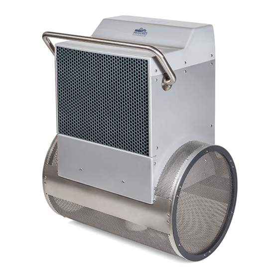
Page 8: General Overview Of Fastlane Pro
The Fastlane Pro can be mounted one of two ways: The Wall Mount Fastlane Pro fastens to the wall of the pool using the bracket provided. Two 1 1/2" (38mm) PVC pipes which serve as conduits for the hydraulic hoses run under the pool deck to a remotely located, 5-horsepower, hydraulic Power Unit, as shown in Figure 1.1. -
Page 9: Choosing A Location For Your Fastlane Pro
12 feet (3,7m) between the wall on which the Fastlane Pro is installed and the opposing wall in line with the Swim Unit. The Fastlane Pro has more than 9 square feet (.83m2) of water intake to eliminate any entrapment hazards. -
Page 10: Wall Mount Bracket
Note: Please read instructions fully prior to installing the wall mount bracket. 4.A. Gunite Pool If the pool being constructed is gunite, please follow the instructions below. The Wall Mount Fastlane Pro Mounting Kit for Gunite pools includes the following: (refer to Fig 4.1) (1) PVC Wall Bracket (2) Bonding Clamp (2) 3/8"... - Page 11 Figures 4.2. and 4.5. The area below the bracket should be no more than 5 degrees less than the vertical down to at least 39" (99cm) below the waterline. The Fastlane Pro is 21"...
- Page 12 Fastlane Pro Swim Unit Installation ® The location of the Hydraulic Power Unit should be determined at this point in the installation. Unroll lengths of 1-1/2" (38mm) flexible PVC pipe from the back of the wall mount bracket to the Power Unit. Any bends in the flexible pipe MUST be gradual sweeps and not sharp to allow the hydraulic hoses to easi- ly be fed through each conduit.
- Page 13 Fastlane Pro Swim Unit Installation ® The threaded rods must be tied into the pools bonding grid. Secure a bonding clamp to each threaded rod. Attach a #8 solid copper wire to each bonding clamp. These wires MUST be attached to a bonding connection that’s incorporated into the pools bonding grid.
-
Page 14: Steel/Polymer Pool With A Vinyl Liner
(1) Clear Silicone Position the PVC template where the Fastlane Pro will attach to the pool wall and align the bottom of the template with the expected water level in the pool (which will typically be located at the centerline of the skimmer) as shown in Figure 4.6. - Page 15 Fastlane Pro Swim Unit Installation ® Install the star thru-wall fittings with the holes for the cover at 12, 3, 6, and 9 (clock positions) as shown in Figure 4.7 Fig. 4.7 Thread the 3/8" (9,5mm) jam nut onto the threaded rod. Thread the hex coupling onto the threaded rod so that half of the hex coupling is threaded onto the rod and the other half that’s facing the pool is protruding off the threaded rod.
- Page 16 Fastlane Pro Swim Unit Installation ® On the inside of the pool, thread the sacrificial 3/8" (9,5mm) steel (with rubber washer) and bolt into the hex coupling through the hole that was previously drilled in the steel wall. Tighten the bolt to secure the assembly (Fig 4.9).
- Page 17 No concrete can be embedded in these areas. Pour the concrete collar around the top flange of the pool en- casing the threaded rods and conduit in place. This encasement will help secure the Fastlane Pro (Fig 4.12). Fig. 4.12...
- Page 18 Fastlane Pro Swim Unit Installation ® After the concrete has cured remove the sacrificial 3/8” (9,5mm) washers and bolts and install the pool liner. Before beginning the liner installation, be sure to note the orientation of the star thru-wall holes at the 12, 3, 6, and 9 (clock positions) as they will be hidden once the liner is installed.
-
Page 19: Gunite Pool With A Vinyl Liner
4.C. Gunite Pool with a Vinyl Liner If the pool being constructed is a gunite pool with a vinyl liner, please follow the instructions below. The Wall Mount Fastlane Pro Mounting Kit for steel/polymer/gunite pools with a vinyl liner includes the following: (1) PVC Wall Bracket (2) Bonding Clamp (2) 3/8”... - Page 20 Fastlane Pro Swim Unit Installation ® Thread the 3/8” (9,5mm) jam nut onto the threaded rod. Thread the hex coupling onto the threaded rod so that half of the hex coupling is threaded onto the rod and the other half that’s facing the pool is protruding off the threaded rod.
- Page 21 Once encased in concrete, these rods will serve as a suitable hanger. The threaded rods must pene- trate 1-1/4" to 1-1/2" (31,8mm x 38mm) into the finished pool and will be used to hang the Fastlane Pro (Fig 4.18).
- Page 22 24ft 6in (7,5m). This will allow the hydraulic hose attached to the Fastlane Pro to terminate just inside the junction box. Refer to section 5 for additional information. The threaded rods must be tied into the pools bonding grid. Secure a bonding clamp to each threaded rod.
- Page 23 Fastlane Pro Swim Unit Installation ® After the liner is installed, add water to the pool to weigh the liner down pulling it tight. When the liner is tight, cut the holes for each thru-wall fitting and threaded rod hole using a sharp utility knife. Cut the holes as small as possible for the threaded rods (Fig 4.22).
-
Page 24: Fiberglass Pool
Remove the hardware from the PVC bracket. In this application the bracket will serve primarily as a tem- plate. Position the bracket on the pool wall where the Fastlane Pro will be placed. Align the etched mark on the bracket with the expected waterline, which is typically halfway up the skimmer opening. The bracket must be level on the pool wall. - Page 25 Fastlane Pro Swim Unit Installation ® Cut the center portion out of the bracket using the etched marks in the brackets as a guide. The two end portions will be used as washers on the backside of the pool wall (Fig 4.25). Fig.
- Page 26 Fastlane Pro Swim Unit Installation ® The backside of the thru-wall holes may need to be sanded flat so that a proper seal can be made. Place one of the rubber gaskets onto each thru-wall fitting. The second rubber gasket will not be used in this applica- tion.
- Page 27 No concrete can be embedded in these areas. When all of the connections on the outside of the pool are complete, a concrete collar should be poured around the threaded rods and conduit. This encasement will help secure the Fastlane Pro (Fig 4.30) Fig. 4.30...
-
Page 28: Junction Box And 1/2" Run Hoses
It is at the junction box where a step up to 1/2" run hose occurs. The hydraulic hose from the Fastlane Pro Swim Unit to the junction box is 3/8" (9,5mm) and the run hose from the junction box to the Power Unit is 1/2". -
Page 29: Assembly Of The Fastlane Pro Swim Unit
The packaging can be collapsed and used as a protective surface upon which to assemble the Fastlane Pro. The foam packing material can be used to wedge under the base to prevent it from tipping over. When assembling the Fastlane Pro, a low torque setting should be used on the drill to prevent the holes in the acrylic from stripping. - Page 30 Fastlane Pro Swim Unit Installation ® 6.4 Remove the throat from the upper housing. There are two screws on each side of the throat. Pull the throat off of the housing and set it aside. Pull the vertical water-conditioning grill up and out of the housing.
- Page 31 ® 6.7 Carefully lay the Fastlane Pro onto its face. Position the hydraulic hoses up the back of the upper hous- ing. The two hat sections will be placed over the hydraulic hoses. Make sure that the mounting hole in the end of the hat section is facing up.
- Page 32 Fastlane Pro Swim Unit Installation ® 6.9 Slide the horizontal water-conditioning grill back into its track inside the housing. The horizontal grill is the wider of the two grills (Fig 6.7). Fig. 6.7 6.10 Install the stainless steel grab bar to the upper housing using the provided stainless steel screws and lock nuts.
- Page 33 Fastlane Pro Swim Unit Installation ® 6.11 Reattach the throat to the upper housing. Again, there will be 2 screws on either side of the throat (Fig 6.9). Fig. 6.9 6.12 Slide the vertical water-conditioning grill back down into the housing (Fig 6.10). Fig.
- Page 34 Fig. 6.11 6.14 Once the Fastlane Pro is installed in the pool, place the housing lid onto the housing and use the pro- vided screws to attach. There will be three screws per side, for a total of six (Fig 6.12).
-
Page 35: Installation Of Your Wall Mount Fastlane Pro
Fig. 7.1 Using two people, carefully lower the Fastlane Pro into the pool. Align the holes at the top of the protective hat sections with the threaded mounting rods and rest the Fastlane Pro into place. The Fastlane Pro will hang from the mounting rods. -
Page 36: Deck Mount Fastlane Pro Hose Cover Tray Installation
DECK MOUNT FASTLANE PRO HOSE COVER TRAY INSTALLATION 8.1 Choose where the Fastlane Pro is to be placed in the pool. The water depth must be 39" (99cm). There must be a minimum of 24" (61cm) between the Fastlane Pro and any adjacent wall or pool obstruction. -
Page 37: Deck Mount Fastlane Pro Installation
Fig. 9.1 9.2 Carefully lay the assembled Fastlane Pro down on its front face. There are six pre-drilled holes in the center of the top housing (between the protective hat channels). Align the top set of holes in the rear of the housing with appropriate number hole in the hanger bracket (if the freeboard is 6"... - Page 38 9.6 Place the Fastlane Pro lid onto the top of the Fastlane Pro and use the six 3/4" (19mm) stainless steel screws that were provided (3 on each side) (See Fig 6.12).
-
Page 39: Installation Of The Hydraulic Power Unit
Fastlane Pro Swim Unit Installation ® Section 10 INSTALLATION OF THE HYDRAULIC POWER UNIT 10.1 Placement Considerations: The Power Unit should be placed on a flat, level surface. If placing outside, it is recommended the Outdoor Power Unit Weather Guard be purchased (see Fig 10.1), but should not be subject to driving rain. -
Page 40: Electrical Requirements For The United States
Fastlane Pro Swim Unit Installation ® Section 11A ELECTRICAL REQUIREMENTS FOR THE UNITED STATES (60HZ) (and countries with similar electrical requirements) A Ground Fault Circuit Interrupter (GFCI) is required for this product. A GFCI is a device that shuts off an electrical circuit when it detects that electricity is flowing along an unintended path. -
Page 41: Electrical Requirements For The Uk
(and countries with similar electrical requirements) The unique design of the Fastlane Pro facilitates sales to UK and international customers. The Fastlane Pro is shipped in kit form for easy assembly and installation into any new conventional pool following the detailed instructions provided. -
Page 42: Equipment Startup
(19L) bucket used to fill the power unit. 12.4 Turn on the Fastlane Pro, making sure to hold the hose firmly in your hand over the bucket. The re- turning hydraulic fluid will flow into the bucket. The system will automatically shut off when the float level switch inside the fluid reservoir is tripped. -
Page 43: Bonding The Fastlane Pro
All Deckmount Fastlane Pro shipments include a copper bonding lug that's pre-attached to the hose cover tray (deck plate). Once the Fastlane Pro is installed into the pool, the stainless steel wire that exits the top of the unit must be attached to the bonding lug on the hose cover tray. A #8 solid copper wire is then attached to the bonding lug which must tie into the pool's bonding grid. -
Page 44: Wall Mount Fastlane Pro Bonding
Fastlane Pro Swim Unit Installation ® Section 13 WALL MOUNTED FASTLANE PRO BONDING Fig. 13.1... -
Page 45: Deck Mount Fastlane Pro Bonding
Fastlane Pro Swim Unit Installation ® Section 13 DECK MOUNTED FASTLANE PRO BONDING Fig. 13.2... - Page 46 Fastlane Pro Swim Unit Installation ® Testing Fastlane Bonding Multi Meter Multi Meter Hydraulic Power Unit Bonding Test Wire Bonding Test Wire Bonding Connection Bonding Connection Metal Reinforcement / Pool Bonding Grid Pool Equipment Attach stainless steel "Bonding Test Wire" to the bonding lug located on the hydraulic power unit. 2) Run the test wire across the pool deck to the Fastlane bonding connection.
-
Page 47: Using Your Fastlane Pro
The hydraulic power unit controller is equipped with a built-in timer, shutting the unit off after 30 minutes. The Fastlane Pro will “remember” the speed of the swim current at which it was turned off and will default to that same speed when the unit is turned back on. -
Page 48: Scheduled Maintenance
16.2 Grill Cleaning. Should you perceive a reduction in speed of your Fastlane Pro, it may be caused by a reduction in water flow due to a blockage of the inlet assembly of the cylindrical base. Because the un-... -
Page 49: Suction Outlet Fitting Service Instructions
® Section 18 SUCTION OUTLET FITTING SERVICE INSTRUCTIONS Suction Outlet Fitting Information: Model: Fastlane Pro Suction Outlet Fitting # 196310 Suction Outlet Fitting Fastener # 710980 Suction Outlet Fitting Replacement Instructions Service Access: The use of adhesives or other attachment methods that prevent access to suction piping or suction outlet fitting components requiring periodic servicing is prohibited. - Page 50 Endless Pools • 1601 Dutton Mill Rd • Aston, PA 19014-2931 D30001 0820 800-910-2714 US • 610-497-8693 fax • www.myendlesspool.com © Copyright 2020 Wellness Marketing Corporation...
Need help?
Do you have a question about the FASTLANE PRO and is the answer not in the manual?
Questions and answers