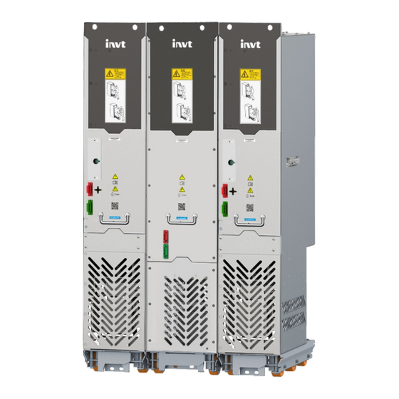
INVT Goodrive800 Pro Series Hardware Manual
Regenerative rectifier
Hide thumbs
Also See for Goodrive800 Pro Series:
- Hardware manual (57 pages) ,
- Hardware manual (83 pages) ,
- Hardware manual (80 pages)
Table of Contents
Advertisement
Quick Links
Advertisement
Table of Contents

Related Manuals for INVT Goodrive800 Pro Series


Summary of Contents for INVT Goodrive800 Pro Series
- Page 2 Goodrive800 Pro Series Regenerative Rectifier Hardware Manual Change history Change description Version Release date First release. V1.0 December 2022 Modified the content in Table 2-2, Table 2-3; Updated the power interface description in V1.1 August 2023 Table 5-1, Table 5-3;...
- Page 4 Goodrive800-81 series is the regenerative rectifier unit of Goodrive800 Pro series. If not otherwise specified, the regenerative rectifier in this manual refers to the regenerative rectifier unit of Goodrive800 Pro series, that is, Goodrive800-81 series product. The rated power of a single unit is 423kW–1027kW, and the max.
-
Page 5: Table Of Contents
Goodrive800 Pro Series Regenerative Rectifier Hardware Manual Contents Contents 1 Safety precautions .............................1 1.1 Safety declaration ..............................1 1.2 Safety definition ..............................1 1.3 Warning symbols ..............................1 1.4 Safety guidelines ..............................2 1.4.1 Delivery and installation ..........................2 1.4.2 Commissioning and running ........................3 1.4.3 Maintenance and component replacement .................... - Page 6 Goodrive800 Pro Series Regenerative Rectifier Hardware Manual Contents 4.3.3 Wiring suggestions ............................ 35 4.3.4 Shielded cable connection ........................37 4.4 Electrical wiring ..............................38 4.4.1 Main circuit wiring ............................ 38 4.4.2 Electrical installation checklist ........................ 41 5 Rectifier Control Unit (RCU) ........................42 5.1 RCU composition ..............................
-
Page 7: Safety Precautions
Goodrive800 Pro Series Regenerative Rectifier Hardware Manual Safety precautions 1 Safety precautions 1.1 Safety declaration Read this manual carefully and follow all safety precautions before moving, installing, operating and servicing the product. Otherwise, equipment damage or physical injury or death may be caused. -
Page 8: Safety Guidelines
Do not refit the Goodrive800 Pro series product unless authorized; otherwise fire, electric shock or other injury may result. The base may become hot when the Goodrive800 Pro series product is running. Do not touch. Otherwise, you may get burnt. -
Page 9: Commissioning And Running
Goodrive800 Pro Series Regenerative Rectifier Hardware Manual Safety precautions 1.4.2 Commissioning and running Cut off all power supplies connected to the regenerative rectifier before terminal wiring, and wait for at least the time designated on the rectifier unit after disconnecting the power supplies. -
Page 10: Product Overview
Product overview 2 Product overview For Goodrive800 Pro series regenerative rectifier, the rated power of a single unit is 423kW–1027kW, while that of parallel units can be up to 5726kW. The regenerative rectifier consists of regenerative rectifier filter unit and regenerative rectifier unit. It is compact in structure and easy to integrate and maintain, reducing cabinet footprint. -
Page 11: Product Nameplate And Model
Goodrive800 Pro Series Regenerative Rectifier Hardware Manual Product overview 2.2 Product nameplate and model Figure 2-1 Product nameplate Note: The preceding nameplate is a standard product nameplate example. The marking varies slightly depending on the model. The model designation code contains basic product information such as rated current and rated voltage. -
Page 12: Overload Capability
Goodrive800 Pro Series Regenerative Rectifier Hardware Manual Product overview Light overload Heavy overload Rating Heat application application dissipation volume Model Structure A (AC) A (DC) A (DC) kVA kW (DC) A (DC) kW (DC) A (DC) kW (DC) m³/h GD800-81-1770-4-01 1770 2168 2818 1226... -
Page 13: Hardware Principles
Goodrive800 Pro Series Regenerative Rectifier Hardware Manual Product overview Figure 2-3 Light overload application Short-time overload current 110% I Rated current I (Continuous) Light overload rating I Based on the heavy overload continuous run current (I ), the regenerative rectifier can keep running for 60s at 150% of the rated current. -
Page 14: Paralleling Principle
Goodrive800 Pro Series Regenerative Rectifier Hardware Manual Product overview Figure 2-5 Simplified main circuit diagram of the regenerative rectifier Regenerative rectifier Regenerative rectifier filter unit unit Regenerative reactor Name Description To protect against overload and short-circuit on the AC fuse regenerative rectifier unit side. - Page 15 Goodrive800 Pro Series Regenerative Rectifier Hardware Manual Product overview Figure 2-6 Simplified parallel system diagram of the regenerative rectifier Regenerative Regenerative rectifier rectifier filter unit unit Regenerative reactor Regenerative rectifier unit Name Description To protect against overload and short-circuit on the AC fuse regenerative rectifier unit side.
-
Page 16: Product Structure
Goodrive800 Pro Series Regenerative Rectifier Hardware Manual Product overview 2.6 Product structure 2.6.1 Layout of L+A8 The following figure shows the frame layout of L+A8. Figure 2-7 Structure of regenerated rectifier frame (L+A8) Name Cabinet Regenerative rectifier unit Regenerative rectifier filter unit Channel steel base 202308 (V1.1) -
Page 17: Layout Of L+2*A8
Goodrive800 Pro Series Regenerative Rectifier Hardware Manual Product overview 2.6.2 Layout of L+2*A8 The following figure shows the frame layout of L+2*A8. Figure 2-8 Structure of regenerated rectifier frame (L+2*A8) Name Cabinet Regenerative rectifier unit Regenerative rectifier filter unit Regenerative rectifier unit Channel steel base 202308 (V1.1) -
Page 18: System Configuration
Goodrive800 Pro Series Regenerative Rectifier Hardware Manual Product overview 2.7 System configuration Figure 2-9 shows the typical topology in which the regenerative rectifier works with three inverter units. Figure 2-9 System configuration Name Transformer Breaker Regenerative rectifier filter unit Regenerative rectifier unit... -
Page 19: Breaker
Goodrive800 Pro Series Regenerative Rectifier Hardware Manual Product overview Recommended Power supply module Rated current Recommended model specification 400V 640–1770A 690V 65A LC1-D65M7C 690V 600–1770A 690V 65A LC1-D65M7C Buffer rectifier bridge 400V 640–1770A 200A, 1600V 3-phase rectifier bridge MDS200-16 3-phase rectifier bridge 690V 600–1770A... -
Page 20: Dc Fuse
900A 2.9 Lightning protection component The product adopts INVT lightning protection component to prevent damage from lightning and surge. The lightning protection component is installed in the incoming cable cabinet and connected to the outgoing side of main circuit breaker. Figure 2-10 shows the dimensions of the component. - Page 21 Goodrive800 Pro Series Regenerative Rectifier Hardware Manual Product overview Table 2-8 Lightning protection component selection Model Grid voltage (V) RV-380V RV-660V 202308 (V1.1)
-
Page 22: Mechanical Installation
Ensure all the input power supplies have been disconnected before wiring or inspection, and wait for at least the time designated on the Goodrive800 Pro series product or until the DC bus voltage is less than 36V. 3.2 Installation environment... -
Page 23: Preparing
Goodrive800 Pro Series Regenerative Rectifier Hardware Manual Mechanical installation Environment Condition Install the equipment in a place: Without the chance Do not install the Away from Away from oil for foreign objects VFD onto electromagneti mist, corrosive such as metal... -
Page 24: Unpacking
Goodrive800 Pro Series Regenerative Rectifier Hardware Manual Mechanical installation Figure 3-1 Transportation requirements When transported with a forklift, the regenerative rectifier must be fixed to the pallets and transported together, which means you are not allowed to remove the pallets to transport the regenerative rectifier. If the forklift's fork tines are too short, it may cause the unit/cabinet to tip over, resulting in serious injury, property damage or even death. -
Page 25: Lifting
Goodrive800 Pro Series Regenerative Rectifier Hardware Manual Mechanical installation Step 2 Use tools such as a pry bar or large one-piece screwdriver to remove the wooden box cover and the steel tongue nails of the surrounding boards. Step 3 Remove the surrounding boards and EPE filling materials from the wooden box. - Page 26 Goodrive800 Pro Series Regenerative Rectifier Hardware Manual Mechanical installation Figure 3-5 Unit top structure Never apply force Lifting ring The regenerative rectifier unit has a high center of gravity and must be placed on a flat and solid ground with sufficient support strength and a tilt angle of less than 5°.
-
Page 27: Installation Space And Heat Dissipation
Goodrive800 Pro Series Regenerative Rectifier Hardware Manual Mechanical installation Figure 3-7 Unfolding the anti-tipping stand Anti-tipping stand Figure 3-8 Folding the anti-tipping stand 3.3.5 Installation space and heat dissipation To ensure that regenerative rectifier units are installed reliably and in good heat dissipation, pay attention to the following: 1. -
Page 28: Cabinet Installation
Goodrive800 Pro Series Regenerative Rectifier Hardware Manual Mechanical installation Figure 3-9 Mounting space requirements Air outlet ≥20 ≥20 ≥20 ≥6 ≥20 Sealing sponge or air baffle Sealing sponge (preventing hot air from circuilating back) Air inlet Air inlet Front view... - Page 29 Goodrive800 Pro Series Regenerative Rectifier Hardware Manual Mechanical installation To fix the bottom support crossbeams and install the unit tray: (1) Use ten M8 cage nuts to fix the five bottom support crossbeams to the base of the nine-fold profile cabinet frame.
- Page 30 Goodrive800 Pro Series Regenerative Rectifier Hardware Manual Mechanical installation Name DC fuse AC fuse Regenerative rectifier unit Regenerative rectifier filter unit Figure 3-13 shows the 600mm-wide cabinet installation for L+A8. Figure 3-13 Installation diagram of L+A8 in an 600mm-wide cabinet...
- Page 31 Goodrive800 Pro Series Regenerative Rectifier Hardware Manual Mechanical installation Name Front sealing sponge Back sealing sponge Left protective plate Note: A 40X40 sealing sponge must be used at the position corresponding to the air baffle in the front/back door panel, which prevents air duct reflow.
- Page 32 Goodrive800 Pro Series Regenerative Rectifier Hardware Manual Mechanical installation Figure 3-15 shows the 850mm-wide cabinet installation for L+2*A8. Figure 3-15 Installation diagram of L+2*A8 in an 850mm-wide cabinet Name Cabinet Unit bottom fixed plate Busbar clamp support Busbar clamp R-phase copper busbar...
- Page 33 Goodrive800 Pro Series Regenerative Rectifier Hardware Manual Mechanical installation 3.3.6.4 Unit installation and replacement The installation procedure is as follows: 1. Insert the unit entry/exit guide rail into the slot of the cabinet front bottom beam. See Figure 3-16. Figure 3-16 Unit entry/exit guide rail placement...
- Page 34 Goodrive800 Pro Series Regenerative Rectifier Hardware Manual Mechanical installation (2) Push the regenerative rectifier unit into the cabinet slowly. See Figure 3-18. Note: Since the regenerative rectifier unit barycenter is too high, use the auxiliary rope for mounting to prevent ...
- Page 35 Goodrive800 Pro Series Regenerative Rectifier Hardware Manual Mechanical installation (4) After confirming that the unit is pushed into place, install the unit fixing screws and remove the unit entry/exit guide rail. See Figure 3-20. Figure 3-20 Unit fixing 4-M8 (5) Install the regenerative rectifier on the other side in the same way.
-
Page 36: Fastening Torque
Goodrive800 Pro Series Regenerative Rectifier Hardware Manual Mechanical installation Figure 3-22 LED keypad structure 37.1 71.3 20.4 71.3 Figure 3-23 Mounting the keypad bracket 82.0 87.0 3.3.7 Fastening torque You need the following tools to install the regenerative rectifier unit: Standard toolbox, including screwdrivers, nut wrenches, socket wrenches Torque wrenches with torques from 1.5 N·m to 100 N·m... -
Page 37: Checklist
Goodrive800 Pro Series Regenerative Rectifier Hardware Manual Mechanical installation 3.3.8 Checklist Operation Compliant Completed Installed the beam for regenerative rectifier fixing in the □ □ nine-fold profile cabinet. Installed the bottom tray for regenerative rectifier fixing in the □ □... -
Page 38: Electrical Installation
Goodrive800 Pro Series Regenerative Rectifier Hardware Manual Electrical installation 4 Electrical installation 4.1 Safety notes All safety precautions in this manual must be read and followed. Only trained and qualified professionals are allowed to carry out the operations mentioned in this chapter. -
Page 39: Emc Regulations
Goodrive800 Pro Series Regenerative Rectifier Hardware Manual Electrical installation 4.3 EMC regulations General knowledge of electromagnetic compatibility EMC is short for electromagnetic compatibility, which refers to the ability of a device or system to function properly in its electromagnetic environment and not constitute an unbearable electromagnetic disturbance to anything in that environment. -
Page 40: Power Cable
Goodrive800 Pro Series Regenerative Rectifier Hardware Manual Electrical installation Three categories of grounding: special pole grounding, common pole grounding and series-wound grounding. Different control system needs to use special pole grounding, different devices in the same control system needs to use common pole grounding, and different devices connected by the same power cables needs to use series-wound grounding. -
Page 41: Control Cable
Goodrive800 Pro Series Regenerative Rectifier Hardware Manual Electrical installation 4.3.2 Control cable All analog signal cables, communication cables, and encoder cables must be shielded cables. Analog signal cables need to be double-shielded twisted-pair cables (as shown in figure a). Use one separate shielded twisted pair for each signal. - Page 42 Goodrive800 Pro Series Regenerative Rectifier Hardware Manual Electrical installation Analog signals and digital signals cannot share a same cable, and their cables must be routed separately. If a control cable and power cable must cross each other, ensure that the angle between them is 90 ...
-
Page 43: Shielded Cable Connection
Goodrive800 Pro Series Regenerative Rectifier Hardware Manual Electrical installation Figure 4-6 Routing multiple types of cable 4.3.4 Shielded cable connection The shield layer of signal cable is grounded at both ends, of which the grounding points must be the same. -
Page 44: Electrical Wiring
Goodrive800 Pro Series Regenerative Rectifier Hardware Manual Electrical installation Figure 4-8 Power cable shield connection Shield layer Shield busbar AC wires Outer layer of wire EMC shield clamp PE potential PE busbar 4.4 Electrical wiring 4.4.1 Main circuit wiring 4.4.1.1 Wiring diagram of the main circuit... - Page 45 Goodrive800 Pro Series Regenerative Rectifier Hardware Manual Electrical installation Table 4-2 Main circuit terminal description for regenerative rectifier filter unit Terminal symbol Description 3PH AC input interface 3PH AC output interface Synchronous voltage detection. RST detection card is R, S, T offered.
- Page 46 Goodrive800 Pro Series Regenerative Rectifier Hardware Manual Electrical installation 4.4.1.2 Main circuit wiring terminals Figure 4-10 Regenerative rectifier filter wiring terminals A ( 4 : 1 ) Description DC pre-buffer terminal RST signal detection terminal, connected with the RST detection card in the main control box.
-
Page 47: Electrical Installation Checklist
Goodrive800 Pro Series Regenerative Rectifier Hardware Manual Electrical installation 4.4.2 Electrical installation checklist Operation Compliant Completed Checked the input and output power wiring and ensured □ □ the wiring positions and voltages were correct. Ensured that the input and output power wiring was □... -
Page 48: Rectifier Control Unit (Rcu)
Goodrive800 Pro Series Regenerative Rectifier Hardware Manual Rectifier Control Unit (RCU) 5 Rectifier Control Unit (RCU) 5.1 RCU composition Figure 5-1 RCU diagram Table 5-1 Components Symbol Component Description Indicator Indicators for the power, run, fault, and status Fiber optic... -
Page 49: Rcu Size And Installation
Goodrive800 Pro Series Regenerative Rectifier Hardware Manual Rectifier Control Unit (RCU) 5.2 RCU size and installation 5.2.1 Preparing 1. Required tools Phillips screwdriver may be required during installation. 2. Fastening torque Screws are used to install the RCU with fastening torque. - Page 50 Goodrive800 Pro Series Regenerative Rectifier Hardware Manual Rectifier Control Unit (RCU) Figure 5-3 RCU installation space diagram Front view Side view Table 5-2 Requirements on RCU installation space (unit: mm) ≥100 ≥100 ≥30 ≥30 ≥100 202308 (V1.1)
-
Page 51: Rcu Installation Procedure
Goodrive800 Pro Series Regenerative Rectifier Hardware Manual Rectifier Control Unit (RCU) 5.2.4 RCU installation procedure Place the RCU as shown in the figure. Use Phillips screwdriver to tighten the four M4 screws to fix the RCU to the metal plate as shown in the figure. -
Page 52: Rcu Interface
Goodrive800 Pro Series Regenerative Rectifier Hardware Manual Rectifier Control Unit (RCU) 5.3 RCU interface Figure 5-5 RCU circuit wiring Multifunction input 1 Multifunction input 2 Analog output 0–10V/0–20mA Multifunction input 3 Multifunction input 4 Multifunction input 5 Analog output -10–10V/-20–20mA... - Page 53 Goodrive800 Pro Series Regenerative Rectifier Hardware Manual Rectifier Control Unit (RCU) Figure 5-6 RCU interface diagram Table 5-3 RCU interface Terminal Category Terminal name Description symbol +10V 10V output power 10V power supply. Max. output 10mA . +24V 24V output power 24V power supply.
-
Page 54: Rst Signal Detection Card
You can choose whether to connect the 485- 120Ω terminal resistor through J5. 5.4 RST signal detection card Models of RST signal detection board: ASY01_PA1112_DT1 (400V), ASY02_PA1112_DT1 (660V). Note: The RST signal detection board is applicable to Goodrive800 Pro series rectifier control units. 202308 (V1.1) - Page 55 Goodrive800 Pro Series Regenerative Rectifier Hardware Manual Rectifier Control Unit (RCU) It is installed on the back of the control board. Terminal structure: FANA FANC Terminal description: Terminal Description Common terminal of main circuit breaker switch-on feedback RLYBK Main circuit breaker switch-on feedback signal...
-
Page 56: Maintenance And Inspection
Goodrive800 Pro Series Regenerative Rectifier Hardware Manual Maintenance and inspection 6 Maintenance and inspection 6.1 Periodical maintenance 6.1.1 Overview Only trained and qualified professionals are allowed to maintain the equipment. Before operating the interior of the equipment: Disconnect the power to the equipment (note that no switch/breaker installed in the cabinet can ... - Page 57 Maintenance and inspection Little maintenance is required when the VFD is installed in an environment that meets requirements. The following table describes the routine maintenance periods recommended by INVT. The following table describes the routine maintenance periods recommended by INVT.
-
Page 58: Replacement Of Wearing Parts
Visual inspection No exception occurs. duct Check whether there are foreign objects attached. For more details about maintenance, contact the local INVT office, or visit our website www.invt.com, and choose Support > Services. 6.2 Replacement of wearing parts 6.2.1 Cooling fan 6.2.1.1 Replacement of regenerative rectifier unit cooling fan... - Page 59 Goodrive800 Pro Series Regenerative Rectifier Hardware Manual Maintenance and inspection Stop the unit, disconnect the AC power supply, and wait for a time no shorter than the waiting time designated on the unit. Remove the fan module front cover from the unit housing.
-
Page 60: Replacement Of Regenerative Rectifier Filter Unit Power Box
Goodrive800 Pro Series Regenerative Rectifier Hardware Manual Maintenance and inspection Figure 6-2 Fan maintenance for the regenerative rectifier filter Front cover Fan box Fan air direction 6.2.2 Replacement of regenerative rectifier filter unit power box To replace the power box of the regenerative rectifier filter unit: Only qualified electricians can perform this task. -
Page 61: Fuse Replacement
Goodrive800 Pro Series Regenerative Rectifier Hardware Manual Maintenance and inspection Figure 6-3 Removing front maintenance plate of the regenerative rectifier filter Front maintenance plate Figure 6-4 Removing power box of the regenerative rectifier filter Step 3: Manually unscrew the screws. -
Page 62: Regenerative Rectifier Unit
Goodrive800 Pro Series Regenerative Rectifier Hardware Manual Maintenance and inspection 4. Remove the upper and lower screws of the fuse. Be careful not to fall the flat washer into the cabinet. As shown in Figure 6-5. 5. Install a new fuse into the cabinet in reverse sequence. - Page 63 Goodrive800 Pro Series Regenerative Rectifier Hardware Manual Maintenance and inspection Figure 6-6 Replacing regenerative rectifier unit Front protective plate Disassemble the (+) and (-) cpooer bars. Remove the connection cables and optical fibers. Unit entry/exit guide rail 202308 (V1.1)
-
Page 64: Appendix A Technical Data
When the altitude of the site where the VFD is installed is lower than 1000 m, the VFD can run at the rated power. When the altitude exceeds 1000m, derate by 1% for every increase of 100m. When the altitude exceeds 3000m, consult the local INVT dealer or office for details. A.1.2.3 Derating due to carrier frequency The VFDs in different power classes are different in carrier frequency. -
Page 65: Grid Specifications
Goodrive800 Pro Series Regenerative Rectifier Hardware Manual Technical data A.2 Grid specifications AC 3PH 380V(-15%) – 440V(+10%) Grid voltage AC 3PH 520V(-15%)–690V(+10%) According to the definition in IEC61439-1, the maximum allowable short-circuit Short-circuit current at the incoming end is 100 kA. Therefore, the VFD is applicable to scenarios... -
Page 66: Vfd Category Of C2
Goodrive800 Pro Series Regenerative Rectifier Hardware Manual Technical data Rated voltage lower than 1000V, non-plug, socket, or mobile devices; power drive systems that must be installed and operated by specialized personnel when applied to the first environment. Note: The EMC standard IEC/EN 61800-3 no longer restricts the power distribution of VFDs, but it specifies their use, installation, and commissioning. -
Page 67: Appendix B Expansion Card
Goodrive800 Pro Series Regenerative Rectifier Hardware Manual Expansion card Appendix B Expansion card B.1 External view Figure B-2 Ethernet + CANopen communication card Figure B-1 Ethernet + PROFIBUS communication card Figure B-3 Ethernet + PROFINET communication card B.2 Naming rule EC –... -
Page 68: Function
Goodrive800 Pro Series Regenerative Rectifier Hardware Manual Expansion card B.3 Function Figure B-4 EC-TX103 communication card outline Name Description Interface with the control Used to connect to the control board board Shielded twisted copper wire transmission is one of the most common PROFIBUS transmission means. - Page 69 Goodrive800 Pro Series Regenerative Rectifier Hardware Manual Expansion card Name Description Status Name Color Function indicator On--The module is online and data exchange can be performed. Online Green Off--The module is not in the online state. On--The module is offline and data exchange cannot be performed.
- Page 70 Goodrive800 Pro Series Regenerative Rectifier Hardware Manual Expansion card Name Description There are two CANopen communication interfaces, a DB9 female connector (A) and a 3-pin open interface terminal (C), either of which you can choose to use. CANopen communication Function...
- Page 71 Goodrive800 Pro Series Regenerative Rectifier Hardware Manual Expansion card Name Description Status Indicati Name Color Status Description indicator Blinking Component in once and Stop stopped state then off Component in Blinking Pre-operation pre-operation state Component in Operation operating state indicator...
- Page 72 Goodrive800 Pro Series Regenerative Rectifier Hardware Manual Expansion card Name Description Ethernet interface 1 for The PROFINET communication card uses two standard RJ45 PROFINET communication interfaces, which do not distinguish the direction and can be swappable. Two standard RJ45 interfaces...
-
Page 73: Appendix C Dimension Drawings
Goodrive800 Pro Series Regenerative Rectifier Hardware Manual Dimension drawings Appendix C Dimension drawings The following figure shows the dimension drawings of the regenerative rectifier filer. Figure C-1 Installation dimensions 2-OB10X16 16.5 16.5 16.5 62.9 56.9 Back view 60 105 2-OB10X16 Top view 202308 (V1.1) - Page 74 Goodrive800 Pro Series Regenerative Rectifier Hardware Manual Dimension drawings The following figure shows the dimension drawings of regenerative rectifier unit Figure C-2 Installation dimensions 70 70 97.5 202308 (V1.1)
- Page 75 Website: www.invt.com 6 6 0 0 1 - 0 1 0 7 8...
Need help?
Do you have a question about the Goodrive800 Pro Series and is the answer not in the manual?
Questions and answers