
Related Manuals for Mase Generators IS 6.1


Summary of Contents for Mase Generators IS 6.1
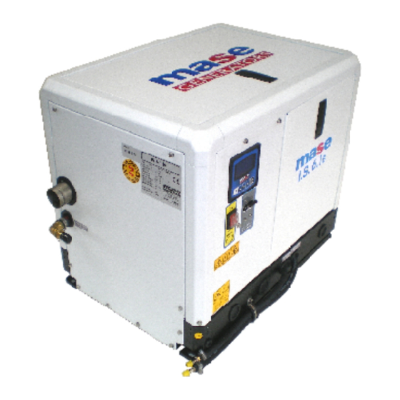
- Page 1 MANUALE USO, MANUTENZIONE E INSTALLAZIONE USE, MAINTENANCE AND INSTALLATION MANUAL IS 6.1 Rev.0 A.A. 09/08/2016 cod.43478 Tipo modello N° matricola Codice...
- Page 2 IS 6.1...
-
Page 3: Table Of Contents
IS 6.1 CONTENTS DEFINITIONS USED ..........5 PRELIMINARY PRESCRIPTIONS ......7 GENERAL INFORMATIONS ......6 MAINTENANCE ..........34 1.1 Conform use ............ 8 6.1 Preamble ............34 1.2 Residual risks ........... 8 6.2 Routine engine maintenance ......34 1.3 Safety symbols ..........9 6.3 Engine oil check .......... -
Page 4: Definitions Used
IS 6.1 DEFINITIONS USED The terms used are current technical terms, and where considered necessary the meaning is described below - Generator An assembly of an internal combustion piston engine and an alternate current, synchronous, 2-4 pole, self- excited generator, joined together to create a station for self-production of electrical energy. - Page 5 IS 6.1 - Connection in bad state The live parts are not fully covered with insulation removable by destruction only, the connections are not secure because of unstable tightening of the parts and a development of oxide between the parts.
-
Page 6: Preliminary Prescriptions
IS 6.1 PRELIMINARY PRESCRIPTIONS FIELD OF EMPLOYMENT: THE GENERATOR IS PROPER FOR TO PRODUCE IN WAY AUTONOMOUS ELECTRIC ENERGY IN THE LIMITS OF TENSION AND WATT DECLARED BY THE BUILDER Consult this manual carefully before proceeding to the use and to any operation on the genset. -
Page 7: General Informations
IS 6.1 1 GENERAL INFORMATIONS 1.1 C ONFORM USE The generator is suitable for independent production of electrical energy within the voltage and wattage limits declared by the manufacturer. Any other use outside the already stated field of use is prohibited: the generator is intended for marine use. -
Page 8: Safety Symbols
IS 6.1 SAFETY INSTRUCTIONS The electromechanics equipments, included the generating sets, switch, command electric equipments and accessories, can cause damages to people and,if they are installed, used or mainteined with not qualified operations, they can put in serious danger the life of people. To avoid accidents is necessary to know the potential risks and operate with caution.Read and follow all the precautions and the instructions for the safety. -
Page 9: Symbols On The Generator Group
IS 6.1 1.4 S YMBOLS ON THE GENERAT OR GROUP Cod. 42653 Cod.42585 Cod. 42655 Cod. 42656 Cod. 42657 Cod. 41781 Cod. 41763 Cod. 42654 cod. 42118 - 10... -
Page 10: Safety Label Informations
IS 6.1 1.5 S AFET Y LABEL INFORMAT IONS • These labels warn the user of any danger which may cause serious injury. Carefully read the meaning and the precautions described in this manual. • If the label detaches or becomes illegible, replace it with a new one which can be requested from an authorised dealer. - Page 11 IS 6.1 Danger Symbols Description PREVENTING FIRE Can cause severe injury or death. • Start • Start the engine only from a starter switch without any load or in neutral posi- tion of the clutch of machine unit. The machine unit suddenly starts to move or generates power to cause serious personal injury.
- Page 12 IS 6.1 Danger Symbols Description EXHAUST SYSTEM Carbon monoxide. Group generator use. Carbon monoxide can cause severe nausea, fainting, or death. Carbon monoxide is an odorless, colorless,tasteless, non irritating gas,able to, if inhaled only also for brief time to provoke the death.
- Page 13 IS 6.1 Danger Symbols Description BATTERY Do not touch the electrolitic battery acid Sufficient ventilation of the battery area. • Keep the area around the battery well ventilated, paying attention to keep sparks, open flame and any other form of ignition away. During engine running or charging battery, hydrogen gas is produced from the battery and can be easily ignited.
-
Page 14: Reference Documents
IS 6.1 1.6 R 1.8 M EFERENCE DOCUMENTS ARKING The instructions for use provided with each generator The generator identification plate carries all the are made up of a collection of documents of which this identification data conforming to ISO 8528 and in manual represents the General Part. -
Page 15: General Characteristics
IS 6.1 2 GENERAL CHARACTERISTICS The generators have been designedfor use in the marine field, using highly reliable 3000/3600 rpm air/water- cooleddiesel engines. Particular attention has been paid to the degree of protection against external agents, engine protection and protection of the electrical parts... -
Page 16: Command And Control Panel
IS 6.1 2.2 C OMMAND AND CONTROL PANEL STANDARD VERSION Each generator is fitted with an instrument panel for commands and controls with the following components: 1) Emergency button 2) General magnetothermal switch 3) Engine protection module 4) Display 5) START / STOP switch... -
Page 17: Table Of Technical Characteristics
IS 6.1 2.3 T ECHNICAL CHARACTERISTICS TABLE MODEL IS 6.1 GENERAL FEATURES MAX POWER (LTP) CONTINUOUS POWER (PRP) POWER FACTOR (Cos F) RATED VOLTAGE RATED FREQUENCY GRADE OF PROTECTION IP 23 °C - °F MAX TEMP. OF USE 40 - 104 MIN TEMP. -
Page 18: Installation
IS 6.1 3 INSTALLATION The generator m ay only be installed by qualified technicians. Malfuncti oning due to im proper installation may cause injury or death. 3.1 G ENERA TOR HOUSING CHARACTERISTICS - The generator must be installed in a sufficiently ventilated room able to assure the small amount of air required for engine combustion. -
Page 19: Cooling Water Circuit
IS 6.1 3.5 C OOLING WATER CIRCUIT The generator engine is cooled by an open-circuit system in which seawater circulates. At the time of installation, a seawater feed circuit must be arranged for cooling, and an exhaust system for the combustion gas and water mixture. -
Page 20: 2Components
IS 6.1 3.5.2 C OMPONENTS If the generator is installed at a height over 1m (3,3ft) above the waterline, a check valve (ref.2) must be fitted after the seawater intake to prevent the water circuit from emptying out when the engine is off. If the circuit is empty, the water pump impeller may be damaged during starting. -
Page 21: 3Typical Installation
IS 6.1 3.5.3 T YPICAL NSTALLATIONS YPICAL INSTALLATION WITH GENERATOR ABOVE THE WATERLINE YPICAL INSTALLATION WITH GENERATOR UNDER THE WATERLINE - 22... - Page 22 IS 6.1 YPICAL INSTALLATION WITH GENERATOR ABOVE THE W ATERLINE WITH WATER GAS SEPARATOR YPICAL INSTALLATION WITH GENERATOR UNDER THE WA TERLINE WITH WATER GAS SEPARATOR - 23...
- Page 23 IS 6.1 YPICAL INSTALLATION WITH GENERATOR ABOVE THE WATERLINE WITH GENSEP WATER GAS SEPARATOR YPICAL INSTALLATION WITH GENERAT OR UNDER THE WATERLINE WITH GENSEP WATER GAS SEPARATOR - 24...
-
Page 24: 4Exhaust System
IS 6.1 3.5.4 E XHAUST SYSTEM The generator combustion “gas/water exhaust” system Muffler must be independent of that of the main engines. See installation diagrams. The pipe length from the highest point of the exhaust pipe to the exhaust must not exceed 2m (6.6... -
Page 25: Fuel Circuit
IS 6.1 3.6 F IRCUIT The generator is diesel-powered by means of the unions marked "DIESEL FUEL INLET" (rif.1) e "DIESEL FUEL OUTLET" (rif.2); the latter serves to return excess fuel. The fuel pipes must be in hydrocarbon-resistant rubber with an inside diameter of 8mm (0.31in). -
Page 26: Electrical Connections
IS 6.1 3.7 E LECTRICAL CONNECTIONS 3.7.1 B A TTERY CONNECTION Use a 12V stand-alone battery to start the generator. Connect it to the generator terminals using cables of 25mm cross-section for a distance up to 5m (16.4ft) cables of 35mm... -
Page 27: Connection
IS 6.1 The control panel must necessarily be installed as it is essential for generator operation. Do not use devices different from the control provided with the generator, since they may be incompatible with the generator. Make the connection with the battery detached. -
Page 28: Generator-Networkswitching
IS 6.1 Feedback to utility. Feedback voltage may cause serious injury or death. Connect the generator to the electrical systemof the structure/boat only through an approved electrical system and after opening the main switch of the structure/boat. The feedback circuit may cause serious injury or death of the personnel working on the power lines and/or personnel near the working area. -
Page 29: Using The Generator
IS 6.1 4 USING THE GENERATOR 4.1 P RELIMINARY HECKS Before beginning with any starting procedures, it is extremely important to “familiarise” yourself with the generator and its controls. Furthermore, visually inspect the generator and the installation. Any source of real or potential risk must be eliminated before proceeding. -
Page 30: Starting The Generator
IS 6.1 4.3 S TARTING THE GENERATOR Before starting the generator check that all the doors is closed. Before starting the generator ensure that all the preliminary checks have been carried out. Start Press the ON/OFF pushbutton (ref.1) to turn on the module. -
Page 31: Safety Switches And Warning Signals
IS 6.1 5 SAFETY SWITCHES AND WARNING SIGNALS 5.1 E NGINE PROTECTION MODULE CBU device (Can-Bus transmission unit) controls and driving the genset. Large display and the control push-buttons allow an easy use and monitoring of the CBU unit. Displayed information... -
Page 32: Protection Against Short Circuits And Overload . 32 5.3 Control Panel - Alarm Codes
IS 6.1 The generators are equipped with a set of safety switches which protect it against improper use and problems which may jeopardise its integrity. 5.3 P ROTECTION AGAINST SHORT CIRCUITS AND OVERLOAD The generator is protected against short-circuits and electrical overload. -
Page 33: Maintenance
IS 6.1 6 MAINTENANCE 6.1 P REAMBLE 6.3 E NGINE HECK It is recommended to strictly follow the instructions in the manual provided by the engine manufacturer, - Check the oil level by means of the cap/dipstick (ref.1). which accompanies each generator. -
Page 34: Engine Oil Change
IS 6.1 6.4 E NGINE OIL CHANGE Use diesel engine oil Top up the engine oil through the hole (ref.1). To change the oil in the engine oil sump, take out the dipstick (ref.2). Suct exhaust oil with a manual pump (ref.3). -
Page 35: Replacing / Cleaning The Fuel Pump Filter
IS 6.1 Do not let the fuel come into contact with the skin. W ea r gl ov es a nd p ro te c ti ve g og gl es d urin g maintenance operations. In the event of contact with fuel, immediately and thoroughly wash the affected part with soap and water. -
Page 36: Draining The Cooling System
IS 6.1 DRAINING THE COOLING SYSTEM In order to carry out maintenance on the water/air Genset exchanger or the cooling system, the seawater intake circuit must be drained. Carry out this operation as follows: - Close the seawater intake cock (ref.1). -
Page 37: Seawater Pump Maintenance
IS 6.1 6.12 S EAWATER PUMP MAINTENANCE At least once a year check the integrity of the rubber seawater pump impeller. Before opening the seawater pump to inspect the impeller, drain the seawater from the cooling system as described in paragraph 6.12. -
Page 38: Checking / Replacing The Alternator V-Belt
IS 6.1 6.13 C HECKING REPLACING THE ALTERNATOR V BELT Asecondbelt is used to transmit the rotary motionfromthe drive shaft pulley to that of the closed-circuit coolant pump and the battery chargerDC alternator (rif.1). Adjust the belt tension as follows: Loosen the adjusting screw (rif.2) and move the battery... -
Page 39: List Of Recommended Spare Parts
IS 6.1 6.16 L IST OF RECOMMENDED SPARE PARTS Description Seawater pump impeller Seawater pump gasket Seawater pump belt Oil filter Fuel filter Zinc anode Fuses A kit with recommended spare parts is available and may be ordered from Service Network or Technical Service. -
Page 40: Period Checks And Maintenance
IS 6.1 6.18 P ERIOD CHECKS AND MAINTENANCE PERIOD CHECKS AND MAINTENANCE Every 50 Every 100 Every 200 Every 400 Before Every 500 Every 800 Perform service at intervals indicated hrs.or 1 hrs.or 2 hrs.or 3 hrs.or starting hrs. hrs. -
Page 41: Anomalies, Causes And Remedies
IS 6.1 6.19 A NOMALIES CAUSES AND REMEDIES The starter motor turns but the main engine does not start - Check that there is fuel in the tank. (Fill up) - Check if the stop electromagnet is in the firing position. (Consult Service Centre) - Check that the emergency button is in ON position. -
Page 42: Handling And Packaging
IS 6.1 7 TRANSPORT, STORAGE, LIFTING AND, HANDLING AND PACKAGING 7.1 T RANSPORT AND ST ORAGE customer Packaging: Supplied directly by The total weight of the packed generator is given in Paragraph 2.3 “Table of technical characteristics”. Transport: During transport the generator (with or... -
Page 43: Guarantee And Responsability
IS 6.1 8 GUARANTEE AND RESPONSIBILITY 8.1 G UARANTEE • Generators and all their components are guaranteed free of defects and are covered by the guarantee for a period as required by current legislation from the date of installation. • Not covered by the guarantee are: failed observance of the installation regulations, damage caused by natural... -
Page 44: Wiring Diagrams
IS 6.1 10 WIRING DIAGRAM TANDARD VERSION - 45... - Page 45 IS 6.1 INSULATED POLE VERSION - 46...
- Page 46 Mase Generators S.p.a. • Via Tortona, 345 • 47522 Cesena (FC) ITALY • Tel. (+39) 0547.35.43.11 Fax (+39) 0547.31.75.55 • www.masegenerators.com • e-mail mase@masegenerators.com...
Need help?
Do you have a question about the IS 6.1 and is the answer not in the manual?
Questions and answers