
Related Manuals for Mase Generators VOYAGER


Summary of Contents for Mase Generators VOYAGER
- Page 1 MANUALE DI USO E MANUTENZIONE USE AND MAINTENANCE MANUAL VOYAGER 6010 Rev.2 F.M. 28/06/2013 cod.43041 Tipo modello N° matricola Codice...
- Page 2 47522 Cesena (FC) Italy Tel.+39-0547-354311 Fax.+39-0547-317555 Dati tecnici, informazioni,stesura dei testi ed allestimenti grafici: a cura dell’Ufficio Tecnico Mase Generators LA DITTA MASE GENERATORS SPA, SI RISERVA TUTTI I DIRITTI SUL PRESENTE MANUALE, NESSUNA RIPRODUZIONE TOTALE O PARZIALE E’ PERMESSA SENZA AUTORIZZAZIONE SCRITTA DELLA DITTA...
-
Page 3: Table Of Contents
VOYAGER 6010 INDICE DEFINIZIONI USATE ..........4 UTILIZZO DEL GRUPPO ELETTROGENO 23 PRESCRIZIONI PRELIMINARI ......6 Avviamento del gruppo elettrogeno ..... 23 Arresto del gruppo elettrogeno ....23 Arresto di emergenza ......... 23 INFORMAZIONI GENERALI ......7 PROTEZIONI ..........24 Uso conforme .......... -
Page 4: Definizioni Usate
VOYAGER 6010 DEFINIZIONI USATE - I vocaboli usati sono quelli del linguaggio tecnico corrente e dove si è ritenuto necessario si riportano di seguito il significato - Gruppo elettrogeno E’ l’insieme di un motore a combustione interna a pistoni e un generatore di corrente alternata sincrono 2/4 poli autoeccitato, uniti tra loro per realizzare una centrale di autoproduzione di energia elettrica. - Page 5 VOYAGER 6010 - Connessione in cattivo stato Le parti attive non sono completamente ricoperte con un isolamento che possa essere rimosso solo mediante distruzione, le connessioni presentano una incertezza nel collegamento causata da un labile serraggio delle parti e da uno sviluppo di ossido fra le parti.
-
Page 6: Prescrizioni Preliminari
VOYAGER 6010 PRESCRIZIONI PRELIMINARI CAMPO D’IMPIEGO: IL GRUPPO ELETTROGENO E’ ADATTO A PRODURRE AUTONONAMENTE ENERGIA ELETTRICA NEI LIMITI DI TENSIONE E WATT DICHIARATI DAL COSTRUTTORE, VEDI TARGA CARATTERISTICHE POSTA SULLA MACCHINA Consultare attentamente questo manuale prima di procedere all’uso ed a qualsiasi intervento sulla macchina. -
Page 7: Informazioni Generali
VOYAGER 6010 1 INFORMAZIONI GENERALI 1.1 Uso conforme Il gruppo elettrogeno è adatto a produrre autonomamente energia elettrica nei limiti di tensione e watt dichiarati dal costruttore. E’ vietato ogni altro uso al di fuori del campo di impiego già citato: la macchina è destinata ad un uso industriale. -
Page 8: Simbologia Sul Gruppo Elettrogeno
VOYAGER 6010 1.3 Simbologia sul gruppo elettrogeno cod. 42348 cod. 41781 Cod. 42349 Cod. 42108 Cod. 42346 Cod. 41777 Cod. 42655 cod. 41781 Cod. 41775 Cod. 42653 cod. 42118 Cod. 41779... -
Page 9: Significato Delle Etichette Di Sicurezza
VOYAGER 6010 1.4 Significato delle etichette di sicurezza • Queste etichette avvertono l’utente su eventuali pericoli che possono causare gravi lesioni. Leggere attentamente il significato e le precauzioni descritte nel presente manuale. • Se l’etichetta si stacca o diventa illeggibile, sostituirla con una nuova richiedendola ad un rivenditore autorizzato... - Page 10 VOYAGER 6010 Simboli di pericolo Significato - Pericolo di impigliamento e taglio: Presenza di parti rotanti, pulegge, cinghie, ventilatore. - Pericolo di ustioni: Superfici calde. - Pericolo di ustioni: Possibilità di espulsione acqua calda in pressione. Simboli di Obbligo Significato - Obbligo collegamento a terra del gruppo elettrogeno.
-
Page 11: Informazioni Generali Di Pericolo
VOYAGER 6010 1.5 Informazioni generali di pericolo • Sia raccomanda la corretta conoscenza sia della modalità di arresto che di funzionamento di tutti i comandi. • Non lasciare che il gruppo elettrogeno venga utilizzato da personale non qualificato. • Anche se la macchina è protetta, evitare di sostare in prossimità del gruppo elettrogeno. -
Page 12: Pericolo Di Lesioni All'udito
VOYAGER 6010 1.5.3 Pericolo di lesioni all’udito • Non sostare per periodi prolungati senza cuffie di protezione, si possono avere riduzioni d’udito. Un esposizione prolungata al di sopra degli 85 dB(A) può provocare disturbi alla salute. Si consiglia in ogni caso l’utilizzo di appropriati sistemi di protezione (es. cuffie, tappi, ecc..). -
Page 13: Pericolo Causato Dall'avvio Del Motore
VOYAGER 6010 1.5.7 Pericolo causato dall’avvio del motore • Non lasciare parti smontate sul motore o nelle vicinanze, oppure attrezzi o quant'altro non facente parte dell'impianto. • Installare le protezioni necessarie per la sicurezza sulle parti di completamento impianto. • Fare funzionare il gruppo elettrogeno il più possibile su di una superficie piana. Per un funzionamento continuo, l’inclinazione massima consentita del motore è... -
Page 14: Informazioni Generali
VOYAGER 6010 2. INFORMAZIONI GENERALI 2.1 Documenti di riferimento 2.3 Marcatura Le istruzioni per l'uso fornite con ciascun gruppo La targa predisposta per i gruppi elettrogeni contiene elettrogeno sono costituite da una raccolta di documenti tutti i dati identificativi secondo quanto richiesto per la di cui il presente manuale rappresenta la Parte Genera- Marcatura CE, per i casi in cui è... -
Page 15: Caratteristiche Generali
VOYAGER 6010 2.5 Caratteristiche generali Il gruppi elettrogeni della serie VOYAGER sono composti da un motore termico alimentato a gasolio accoppiato ad un alternatore che produce corrente alternata e continua, sono stati progettati per assicurare agli utilizzatori professionali il massimo dell'efficienza ed affidabilità per ogni tipo di lavoro. -
Page 16: Allestimento
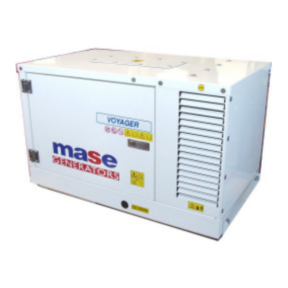
VOYAGER 6010 2.7 Allestimento 2.8 Composizione dei gruppi elettrogeni Vedere Fig.1 I gruppi elettrogeni sono composti essenzialmente dai seguenti componenti: 1 Telaio base 2 Cofano apribile lato motore 3 Piede d'appoggio 4 Pannellino comandi 5 Serratura con chiave 6 Motore 7 Alternatore Fig.1... -
Page 17: Installazione
è corrispondente a IP23 che consente l’uso del gruppo all’aperto. 3.2 Ventilazione Il gruppo elettrogeno Voyager 6010 è dotato di un sistema interno di raffreddamento ad aria forzata. L’aria, necessaria al raffreddamento e alla combustione, è aspirata all’interno della cassa insonorizzante attraverso una griglia posta sotto il pianale ed espulsa dalla cassa in vari allestimenti. -
Page 18: Collegamento Marmitta E Silenziatore
VOYAGER 6010 3.5 Collegamento marmitta e silenziatore Il gruppo viene fornito con una marmitta, una staffa ed una fascetta. La marmitta può essere montata posterior- mente alla cassa utilizzando l’apposita staffa, in dota- zione, per il suo ancoraggio. Come indicato alla fig. 2 la marmitta può... -
Page 19: Kit Silenziatore (Optional)
3 fascette (vedere Fig. 10). Fig.10 3.7 Circuito combustibile Il gruppo VOYAGER va alimentato a gasolio e non disponen- do di serbatoio al suo interno, deve essere collegato ad un serbatoio esterno che può essere anche quello dell’auto- mezzo. -
Page 20: Collegamenti Circuito Combustibile
VOYAGER 6010 3.8 Collegamenti circuito combustibile All’interno del gruppo si trovano i due raccordi (Fig. 13 rif. 1) contraddistinti dalle diciture “GASO-LIO” e “RITOR- NO GASOLIO” ai quali vanno collegati i tubi provenienti dal serbatoio (Fig. 13 rif. 2) E’ importante che tutti i collegamenti vengano assicurati con fascette in grado di garantire la massima tenuta ed evitare che penetrino, all’interno del circuito di alimentazione, bolle... -
Page 21: Collegamenti Elettrici
VOYAGER 6010 3.12 Allacciamento pannello comandi 3.10 Collegamenti elettrici Durante la fase d’installazione del gruppo VOYAGER è Tutte le funzioni di controllo, avviamento e spegnimento, necessario eseguire una serie di collegamenti elettrici. sono gestite dal pannello comandi remoto. Al gruppo dovranno essere collegati: Questo va collegato al gruppo VOYAGER attraverso un una batteria a 12 volt, il pannello comandi e i carichi elettrici. -
Page 22: Collegamenti Degli Utilizzi
VOYAGER 6010 IMPORTANTE IMPORTANTE Il cruscotto va necessariamente installato per il fatto Assicurarsi che la somma dei carichi da alimentare che è assolutamente indispensabile al funzionamen- non superi la potenza nominale del gruppo to del gruppo. E’ vivamente sconsigliato utilizzare elettrogeno. -
Page 23: Utilizzo Del Gruppo Elettrogeno
VOYAGER 6010 4. UTILIZZO DEL GRUPPO ELETTROGENO 4.1 A VVIAMENTO DEL GRUPPO ELETTROGENO Prima di avviare il gruppo elettrogeno assicurarsi che tutti gli sportelli siano chiusi. Procedere all’avviamento premendo il tasto “ON” (rif. 4). L'elettroventola radiatore entrerà immediatamente in funzione. -
Page 24: Protezioni
VOYAGER 6010 5 PROTEZIONI 5.1 Cruscotto comandi - Codici allarmi Quando il gruppo si arresta, per l’intervento di una protezione, sul display (rif.1) del pannello comandi scompare l’indicazione delle ore di funzionamento e compare un codice ad indicare la causa dell’arresto del gruppo elettrogeno. Nella tabella sono... -
Page 25: Manutenzione
VOYAGER 6010 6 MANUTENZIONE 6.3 C ONTROLLO OLIO MOTORE 6.1 P REMESSA - Controllare il livello dell’olio tramite l’apposito tappo/ astina olio (rif.1). Il livello dell’olio deve sempre essere Si raccomanda di seguire scrupolosamente le indicazioni compreso tra le tacche di MAX e MIN incise sull’astina. -
Page 26: Cambio Olio Motore
VOYAGER 6010 6.4 C AMBIO OLIO MOTORE Utilizzare olio per motori diesel I rabbocchi e i caricamenti di olio motore vanno eseguiti attraverso il foro (rif.1).Per la sostituzione dell’olio nel carter motore si procede togliendo l’astina di indicazione livello (rif.2). -
Page 27: Sostituzione / Pulizia Del Filtro Pompa Carburante
VOYAGER 6010 6.6 S OSTITUZIONE PULIZIA DEL FILTRO POMPA CARBURANTE Tale operazione si esegue tramite i seguenti passaggi: - rimuovere il tubo (rif.1) - sfilare il filtro (rif.2) - pulire o sostituire Per il rimontaggio ripetere le operazioni con sequenza inversa. -
Page 28: Controllo Della Tensione Della Cinghia Trapezoidale
VOYAGER 6010 6.10 Controllo della tensione della cinghia 6.12 Sostituzione del liquido refrigerante trapezoidale Ogni anno sostituire il liquido refrigerante all'interno del La cinghia è utilizzata per trasmettere il moto di rotazione circuito chiuso di raffreddamento. dalla puleggia dell'albero motore a quella della pompa del... -
Page 29: Manutenzione Dell'alternatore
VOYAGER 6010 6.15 Periodo di inattività 6.13 Manutenzione dell'alternatore L'alternatore impiegato su questo modello di generatore Se il gruppo deve rimanere inutilizzato per un lungo è di tipo sincrono, autoeccitato, con regolazione elettro- periodo è necessario eseguire le seguenti operazioni. -
Page 30: Controlli Periodici E Manutenzione
VOYAGER 6010 6.16 CONTROLLI PERIODICI E MANUTENZIONE CONTROLLI PERIODICI E MANUTENZIONE Ogni Prima Ogni 50 ore o Ogni 100 ore Ogni 200 ore Ogni 400 ore o Ogni 1.000 ore Ogni 2.000 ore Ogni 500 ore o Manutenzione agli intervalli indicati 30.000... -
Page 31: Anomalie, Cause Rimedi
VOYAGER 6010 7. ANOMALIE, CAUSE RIMEDI 7.1 Tavola guasti Il motorino di avviamento gira ma il motore principale non si avvia. - Verificare se l’elettromagnete di stop è in posizione di tiro. (Consultare Centro Assistenza). - Eseguire l'operazione di spurgo da bolle d'aria all'interno del circuito di alimentazione. -
Page 32: Trasporto, Imballo, Stoccaggio, Sollevamento E Movimentazione
VOYAGER 6010 8. TRASPORTO, IMBALLO, STOCCAGGIO, SOLLEVAMENTO E MOVIMENTAZIONE 8.1 T RASPORTO IMBALLO E STOCCAGGIO Imballo: Viene fornito direttamente dalla ditta Mase Generators. Il peso totale del gruppo elettrogeno imballato si trova al paragrafo 2.3 “Tabella caratteristiche tecniche”. Trasporto: Durante il trasporto, il gruppo elettrogeno,... -
Page 33: Garanzia E Responsabilita
9.2 L IMITI DI RESPONSABILITÀ MASE GENERATORS S.p.a si ritiene responsabile per quanto concerne la sicurezza, l’affidabilità e le prestazioni del Gruppo a patto che: • L’uso del gruppo elettrogeno avvenga da persone precedentemente istruite da libretto uso e manutenzione. -
Page 34: Schemi Elettrici
VOYAGER 6010 11 SCHEMI ELETTRICI 11.1 S CHEMA ELETTRICO VERSIONE MANUALE - 34... - Page 35 VOYAGER 6010 11.2 S CHEMA ELETTRICO VERSIONE AUTOMATICA - 35...
- Page 36 Generators began as a company producing 500 Watt, light and compact portable generators. These generators made the Mase Generators name well known throughout the world. Mase Generators is a leader in high quality, reliable products, and innovative research performed by Research and Development Department.
- Page 37 VOYAGER 6010 CONTENT DEFINITIONS USED ..........4 USING THE GENERATOR ......23 PRELIMINARY PRESCRIPTIONS ......6 Starting the generator ........23 Stopping the generator ......... 23 Emergency stop ........... 23 GENERAL INFORMATION ......7 Conform use ........... 7 SAFETY DEVICES ......... 24 Residual risk ..........
-
Page 38: Definitions Used
VOYAGER 6010 DEFINITIONS USED - The terms used are current technical terms, and where considered necessary the meaning is described below - Generator An assembly of an internal combustion piston engine and an alternate current, synchronous, 2-4 pole, self-excited generator, joined together to create a station for self-production of electrical energy. - Page 39 VOYAGER 6010 - Connection in bad state The live parts are not fully covered with insulation removable by destruction only, the connections are not secure because of unstable tightening of the parts and a development of oxide between the parts.
-
Page 40: Preliminary Prescriptions
Ongoing improvement and development of the product may have led to modifications to the generator which are not included in this publication. Whenever a problem concerning the generator or this publication arises, consult with Mase Generators SPA for the latest information available. -
Page 41: General Information
VOYAGER 6010 1 GENERAL INFORMATIONS 1.1 Conform use The generator is suitable for independent production of electrical energy within the voltage and wattage limits declared by the manufacturer. Any other use outside the already stated field of use is prohibited: the generator is intended for industrial use. -
Page 42: Symbols On The Generator Group
VOYAGER 6010 1.3 Symbols on the generator group cod. 42348 cod. 41781 Cod. 42349 Cod. 42108 Cod. 42346 Cod. 41777 Cod. 42655 cod. 41781 Cod. 41775 Cod. 42653 cod. 42118 Cod. 41779... -
Page 43: Position Of Safety Labels
VOYAGER 6010 1.4 Position of safety labels • These labels warn the user of any danger which may cause serious injury. Carefully read the meaning and the precautions described in this manual. • If the label detaches or becomes illegible, replace it with a new one which can be requested from an authorised mase dealer. - Page 44 VOYAGER 6010 Danger Symbols Meaning - Danger of entanglement and cutting: Presence of rotating parts, pulleys, belts and fan. - Danger of burns: Hot surfaces. - Danger of burns: Possibility of pressurised hot water expulsion. Obligation Symbols Meaning - Obligation to connect the generator to earth.
-
Page 45: General Danger Information
VOYAGER 6010 1.5 General danger informations • It is recommended to learn how to stop and operate all the controls. • Do not allow unqualified personnel to use the generator. • Even though the generator is protected, do not stand near it. -
Page 46: Danger Of Harm To Hearing
VOYAGER 6010 1.5.3 Danger of harm to hearing • Do not stand near the generator for long periods without protective earmuffs since hearing may be reduced. Prolonged exposure to noise above 85 dB(A) may cause health disorders. It is in any case recommended to use appropriate protection systems (e.g. -
Page 47: Danger Caused By The Engine Starting
VOYAGER 6010 1.5.7 Danger caused by the engine starting • Do not leave disassembled parts, tools or anything else not forming part of the system on or near the engine. • Install the protections necessary for safety on the parts completing the system. -
Page 48: General Information
VOYAGER 6010 2. GENERAL INFORMATION 2.1 Reference documents 2.3 Marking The instructions for use provided with each generator are The generator identification plate carries all the made up of a collection of documents of which this manual identification data in accordance with the provisions for represents the General Part. -
Page 49: General Characteristics
VOYAGER 6010 2.5 General characteristics The VOYAGER series generators are composed of a diesel-powered combustion engine coupled to an alternator which produces alternating and direct current. They have been designed to assure professional users maximum efficiency and reliability for any type of work. -
Page 50: Configurations
VOYAGER 6010 2.7 Configuration 2.8 Generator composition See Fig. 1 The generators are essentially composed of the following components: 1 Base chassis 2 Openable cowling engine side 3 Support foot 4 Control panel 5 Lock with key 6 Engine 7 Alternator Fig.1... -
Page 51: Installation
“INSTALLATION” must be carried out by specialised installers only. 3.1 Features Voyager 6010 is a generator designed for installation on motor vehicles, but can nonetheless be used in a fixed place taking care to leave the cooling air intake and free escape vents . -
Page 52: Exhaust Silencer Connection
VOYAGER 6010 3.5 Exhaust silencer connection The generator is equipped with an exhaust, a bracket and a clamp. The exhaust can be fitted at the back of the casing using the bracket provided. As shown in Fig. 8, the exhaust can be turned in four different directions to meet various installation needs. -
Page 53: Silencer Kit
(Fig. 10) Fig.10 3.7 Fuel circuit The VOYAGER generator runs on diesel oil and, not being fitted with a tank, has to be connected to an external tank, which can also be that of the motor vehicle itself. The generator is fitted with a suction-compression pump (SC), able to pump fuel up to a maximum height of 50 cm (Fig. -
Page 54: Fuel Circuit Connection
VOYAGER 6010 3.8 Fuel circuit connection Inside the generator are two pipe fittings (Fig. 13 Ref. 1) marked ‘DIESEL OIL’ and ‘DIESEL OIL RETURN’ to which the pipes from the tank must be connected. (Fig. 13 Ref. 2) It is important to secure all connections with clamps able to guarantee maximum air-tightness in order to prevent air bubbles penetrating inside the feed circuit. -
Page 55: Electrical Connection
The generator must remote control panel. be connected to: It will be connected to VOYAGER through a multipolar a 12-V battery, the control panel and the power loads. cable connected to the relay board (ref. 2) and fixed to These operations must be carried out with great care and remote connector (ref. -
Page 56: Power Connection
VOYAGER 6010 IMPORTANT IMPORTANT The control panel must be installed because it is Make sure that the sum of the loads does not exceed indispensable for correct generator operation. We the power rating of the generator. never recommend using instruments different from the panel supplied with the generator as these may 3.14 Earthing... -
Page 57: Using The Generator
VOYAGER 6010 4. USING THE GENERATOR 4.1 S TARTING THE GENERATOR Before starting the generator check that all the doors is closed. Push the ON button (ref.4). The electric radiator fan will start immediatelly. All the LEDs light on during the self-test for about 5 seconds. -
Page 58: Safety Devices
VOYAGER 6010 5 SAFETY DEVICES 5.1 C ONTROL ANEL LARM ODES When the generator stops because one of the safety switches has tripped, the indication of the hours of operation disappears from the control panel display (ref.1) and a code appears to indicate the cause of the generator stop. -
Page 59: Maintenance
VOYAGER 6010 6 MAINTENANCE 6.3 E NGINE HECK - Check the oil level by means of the cap/dipstick (ref.1). 6.1 P REAMBLE The oil level must always be between the MAX and MIN It is recommended to strictly follow the instructions notches engraved on the dipstick. -
Page 60: Engine Oil Change
VOYAGER 6010 6.4 E NGINE OIL CHANGE Use diesel engine oil Top up the engine oil through the hole (ref.1). To change the oil in the engine oil sump, take out the dipstick (ref.2). Unscrew the cap on the rubber pipe (ref.3) and make flow out the oil. -
Page 61: Replacing / Cleaning The Fuel Pump Filter
VOYAGER 6010 6.6 R EPLACING LEANING ILTER This operation is carried out following the steps below: - Remove the pipe (ref.1) - Slide out the filter (ref.2) - Clean or replace it For reassembly repeat the operations in reverse order. -
Page 62: Checking The V-Belt Tension
VOYAGER 6010 6.10 Checking the V-belt tension 6.12 Coolant replace The belt is used to transmit the rotary motion from the Replace the coolant every year inside the closed circuit pulley of the drive shaft to that of the closed-circuit fluid of cooling. -
Page 63: Alternator Maintenance
VOYAGER 6010 6.13 Alternator maintenance 6.15 Period of inactivity The alternator used on this model is the synchronous, self- If the generator is not to be used for long time, do the excited type with electronic voltage control. This model following operations. -
Page 64: Periodic Checks And Maintenance
VOYAGER 6010 6.16 P ERIODIC CHECKS AND MAINTENANCE PERIOD CHECKS AND MAINTENANCE Every 50 Every 100 Every 200 Every 400 Every 500 Every 1.000 Every 2.000 Every Before Perform service at intervals indicated hrs. or 1 hrs. or 2 hrs. or 3 hrs. -
Page 65: Anomalies, Causes And Remedies
VOYAGER 6010 7 ANOMALIES, CAUSES AND REMEDIES 7.1 Breackdown table The starter motor turns but the main engine does not start - Check that the stop solenoid valve is powered. (Consult Service Centre). - Perform operations of drainage from air beads inside the fuel circuit The engine protection module is not activated pressing the pulsating START - Check if the thermal interrupter of protection is open. -
Page 66: And Packaging
8 TRANSPORT, STORAGE, LIFTING AND, HANDLING AND PACKAGING 8.1 T RANSPORT AND STORAGE Packaging: Supplied directly by Mase Generators. The total weight of the packed generator is given in Paragraph 2.3 “Table of technical characteristics”. Transport: During transport the generator (with or without... -
Page 67: Guarantee And Responsibility
9.2 L IMITS OF RESPONSIBILITY MASE GENERATORS S.p.A is responsible for anything regarding the safety, reliability and performance of the Generator on the condition that: • The generator is used by persons trained through the use and maintenance manual. -
Page 68: Wiring Diagram
VOYAGER 6010 11. WIRING DIAGRAM 11.1 W IRING DIAGRAM MANUAL VERSION - 34... - Page 69 VOYAGER 6010 11.2 W IRING DIAGRAM AUTOMATIC VERSION - 35...
- Page 70 Mase Generators S.p.a. • Via Tortona, 345 • 47522 Cesena (FC) ITALY • Tel. (+39) 0547.35.43.11 Fax (+39) 0547.31.75.55 • www.masegenerators.com • e-mail mase@masegenerators.com...
Need help?
Do you have a question about the VOYAGER and is the answer not in the manual?
Questions and answers