
Related Manuals for Mase Generators Voyager 6020 Auto


Summary of Contents for Mase Generators Voyager 6020 Auto
- Page 1 MANUALE DI USO E MANUTENZIONE USE AND MAINTENANCE MANUAL VOYAGER 6020 AUTO Rev.2 F.M. 28/06/2013 cod.43186 Tipo modello N° matricola Codice...
- Page 2 47023 Cesena (FC) Italy Tel.+39-0547-354311 Fax.+39-0547-317555 Dati tecnici, informazioni,stesura dei testi ed allestimenti grafici: a cura dell’Ufficio Tecnico Mase Generators LA DITTA MASE GENERATORS SPA, SI RISERVA TUTTI I DIRITTI SUL PRESENTE MANUALE, NESSUNA RIPRODUZIONE TOTALE O PARZIALE E’ PERMESSA SENZA AUTORIZZAZIONE SCRITTA DELLA DITTA...
- Page 3 Generators began as a company producing 500 Watt, light and compact portable generators. These generators made the Mase Generators name well known throughout the world. Mase Generators is a leader in high quality, reliable products, and innovative research performed by Research and Development Department.
-
Page 4: Table Of Contents
VOYAGER 6020 CONTENT DEFINITIONS USED ..........4 USING THE GENERATOR ......23 PRELIMINARY PRESCRIPTIONS ......6 Manual starting the generator ....... 23 Stopping the generator ......... 23 Emergency stop ........... 23 GENERAL INFORMATION ......7 Conform use ........... 7 AUTOMATIC MODE ........24 Residual risk .......... -
Page 5: Definitions Used
VOYAGER 6020 DEFINITIONS USED - The terms used are current technical terms, and where considered necessary the meaning is described below - Generator An assembly of an internal combustion piston engine and an alternate current, synchronous, 2-4 pole, self-excited generator, joined together to create a station for self-production of electrical energy. - User system Composed of the power supply circuits of the user equipment, including the relevant sectioning, handling, breaking, transformation, protection, etc. - Page 6 VOYAGER 6020 - Connection in bad state The live parts are not fully covered with insulation removable by destruction only, the connections are not secure because of unstable tightening of the parts and a development of oxide between the parts. - Direct contact Contact of persons or animals with live parts - Control circuit...
-
Page 7: Preliminary Prescriptions
Ongoing improvement and development of the product may have led to modifications to the generator which are not included in this publication. Whenever a problem concerning the generator or this publication arises, consult with Mase Generators SPA for the latest information available. -
Page 8: General Information
VOYAGER 6020 1 GENERAL INFORMATIONS 1.1 Conform use The generator is suitable for independent production of electrical energy within the voltage and wattage limits declared by the manufacturer. Any other use outside the already stated field of use is prohibited: the generator is intended for industrial use. The generator has been designed to operate independently (without operator) if not for sporadic checks. -
Page 9: Symbols On The Generator Group
VOYAGER 6020 1.3 Symbols on the generator group cod. 42348 cod. 41781 Cod. 42349 Cod. 42655 Cod. 42108 Cod. 42346 Cod. 42861 Cod. 41777 cod. 41781 cod. 42118 Cod. 42653 Cod. 41775 Cod. 41779... -
Page 10: Position Of Safety Labels
VOYAGER 6020 1.4 Position of safety labels • These labels warn the user of any danger which may cause serious injury. Carefully read the meaning and the precautions described in this manual. • If the label detaches or becomes illegible, replace it with a new one which can be requested from an authorised mase dealer. - Page 11 VOYAGER 6020 Danger Symbols Meaning - Danger of entanglement and cutting: Presence of rotating parts, pulleys, belts and fan. - Danger of burns: Hot surfaces. - Danger of burns: Possibility of pressurised hot water expulsion. Obligation Symbols Meaning - Obligation to connect the generator to earth. - Obligation to wear eyes protection.
-
Page 12: General Danger Information
VOYAGER 6020 1.5 General danger informations • It is recommended to learn how to stop and operate all the controls. • Do not allow unqualified personnel to use the generator. • Even though the generator is protected, do not stand near it. •... -
Page 13: Danger Of Harm To Hearing
VOYAGER 6020 1.5.3 Danger of harm to hearing • Do not stand near the generator for long periods without protective earmuffs since hearing may be reduced. Prolonged exposure to noise above 85 dB(A) may cause health disorders. It is in any case recommended to use appropriate protection systems (e.g. -
Page 14: Danger Caused By The Engine Starting
VOYAGER 6020 1.5.7 Danger caused by the engine starting • Do not leave disassembled parts, tools or anything else not forming part of the system on or near the engine. • Install the protections necessary for safety on the parts completing the system. •... -
Page 15: General Information
VOYAGER 6020 2. GENERAL INFORMATION 2.1 Reference documents 2.3 Marking The instructions for use provided with each generator are The generator identification plate carries all the made up of a collection of documents of which this manual identification data in accordance with the provisions for represents the General Part. -
Page 16: General Characteristics
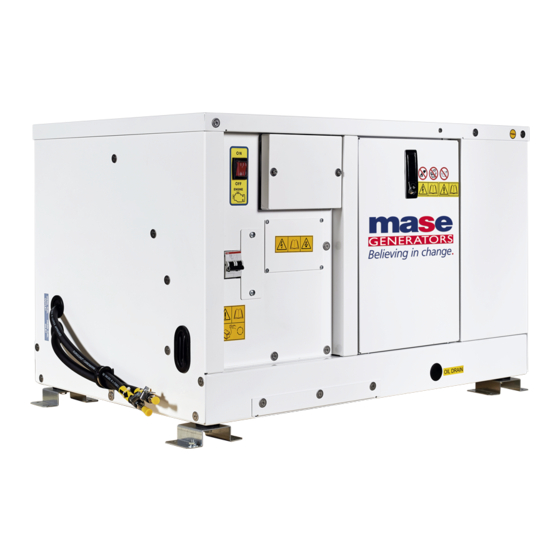
VOYAGER 6020 2.5 General characteristics The VOYAGER series generators are composed of a diesel-powered combustion engine coupled to an alternator which produces alternating and direct current. They have been designed to assure professional users maximum efficiency and reliability for any type of work. The machine is enclosed in a painted sheet steel casing soundproofed with sound-absorbent material. -
Page 17: Configurations
VOYAGER 6020 2.7 Configuration 2.8 Generator composition See Fig. 1 The generators are essentially composed of the following components: 1 Base chassis 2 Openable cowling engine side 3 Support foot 4 Control panel 5 Lock with key 6 Engine 7 Alternator Fig.1 Instrument and control panel See Fig. -
Page 18: Installation
VOYAGER 6020 3. INSTALLATION All the instructions provided in the chapter “INSTALLATION” must be carried out by specialised installers only. 3.1 Features Voyager 6020 is a generator designed for installation on motor vehicles, but can nonetheless be used in a fixed place taking care to leave the cooling air intake and free escape vents . -
Page 19: Exhaust Silencer Connection
VOYAGER 6020 3.5 Exhaust silencer connection The generator is equipped with an exhaust, a bracket and a clamp. The exhaust can be fitted at the back of the casing using the bracket provided. As shown in Fig. 8, the exhaust can be turned in four different directions to meet various installation needs. -
Page 20: Silencer Kit
VOYAGER 6020 3.5 Silencer kit (optional) The kit includes: a silencer, a bracket for fitting the exhaust, a flexible pipe 2 metres long, an elbow, 3 clamps. (Fig. 10) Fig.11 3.7 Fuel circuit The VOYAGER generator runs on diesel oil and, not being fitted with a tank, has to be connected to an external tank, which can also be that of the motor vehicle itself. -
Page 21: Fuel Circuit Connection
VOYAGER 6020 3.8 Fuel circuit connection Inside the generator are two pipe fittings (Fig. 13 Ref. 1) marked ‘DIESEL OIL’ and ‘DIESEL OIL RETURN’ to which the pipes from the tank must be connected. (Fig. 13 Ref. 2) It is important to secure all connections with clamps able to guarantee maximum air-tightness in order to prevent air bubbles penetrating inside the feed circuit. -
Page 22: Electrical Connection
VOYAGER 6020 3.12 Control panel connection 3.10 Electrical connection All control, start and stop functions are controlled by the During the VOYAGER generator installation, a series of remote control panel. power connections must be made. The generator must It will be connected to VOYAGER through a multipolar be connected to: a 12-V battery, the control panel and the power loads. -
Page 23: Power Connection
VOYAGER 6020 Magnetothermal switch protects the generator from overloads or shorts circuits. For connections, always use leads with adequate cross The control panel must be installed because it is sections. indispensable for correct generator operation. We never recommend using instruments different from the panel supplied with the generator as these may not be compatible with the generator itself. -
Page 24: Using The Generator
VOYAGER 6020 4. USING THE GENERATOR 4.1 M ANUAL STARTING THE GENERATOR Before starting the generator check that all the doors is closed. Push the green button (ref.1). The electric radiator fan will start immediatelly. The genset will starts automatically after a little glowplug- preheating delay. -
Page 25: Automatic Mode
VOYAGER 6020 5 AUTO MODE 5.1 AUTO mode It is possible to start/stop the generator automatically, with remote signal on demand. Connect the automatic contact on demand on clamp ref.1-3 (contact n.o. --> STOP, n.c. --> START). Set automatic mode pressing AUTO pushbutton (ref.2). Icon appears on display if no alarm are present. -
Page 26: Maintenance
VOYAGER 6020 6 MAINTENANCE 6.3 E NGINE HECK - Check the oil level by means of the cap/dipstick (ref.1). 6.1 P REAMBLE The oil level must always be between the MAX and MIN It is recommended to strictly follow the instructions notches engraved on the dipstick. -
Page 27: Engine Oil Change
VOYAGER 6020 6.4 E NGINE OIL CHANGE Use diesel engine oil Top up the engine oil through the hole (ref.1). To change the oil in the engine oil sump, take out the dipstick (ref.2). Unscrew the cap on the rubber pipe (ref.3) and make flow out the oil. -
Page 28: Replacing / Cleaning The Fuel Pump Filter
VOYAGER 6020 6.6 R EPLACING LEANING ILTER This operation is carried out following the steps below: - Remove the pipe (ref.1) - Slide out the filter (ref.2) - Clean or replace it For reassembly repeat the operations in reverse order. After replacing the filter, the fuel system has to be bled by carrying out the operations described in paragraph 6.8. -
Page 29: Checking The V-Belt Tension
VOYAGER 6020 6.10 Checking the V-belt tension 6.12 Coolant replace The belt is used to transmit the rotary motion from the Replace the coolant every year inside the closed circuit pulley of the drive shaft to that of the closed-circuit fluid of cooling. -
Page 30: Alternator Maintenance
VOYAGER 6020 6.13 Alternator maintenance 6.15 Period of inactivity The alternator used on this model is the synchronous, self- If the generator is not to be used for long time, do the excited type with electronic voltage control. This model following operations. -
Page 31: Periodic Checks And Maintenance
VOYAGER 6020 6.16 P ERIODIC CHECKS AND MAINTENANCE PERIOD CHECKS AND MAINTENANCE Every 50 Every 100 Every 200 Every 400 Every 500 Every 1.000 Every 2.000 Every Before Perform service at intervals indicated hrs. or 1 hrs. or 2 hrs. or 3 hrs. -
Page 32: Anomalies, Causes And Remedies
VOYAGER 6020 7 ANOMALIES, CAUSES AND REMEDIES 7.1 Breackdown table The starter motor turns but the main engine does not start - Check that the stop solenoid valve is powered. (Consult Service Centre). - Perform operations of drainage from air beads inside the fuel circuit The engine protection module is not activated pressing the pulsating START - Check if the thermal interrupter of protection is open. -
Page 33: Packaging
VOYAGER 6020 8 TRANSPORT, STORAGE, LIFTING AND HANDLING 8.1 Transport and storage mase Packaging: Supplied directly by The total weight of the packed generator is given in Paragraph 2.6 “Table of technical characteristics”. It is strictly prohibited to pollute the environment with the packaging Transport: During transport the generator (with or without packaging) must be protected against atmospheric agents, it must not be turned upside down and must be protected against knocks. -
Page 34: Guarantee And Responsibility
9.2 L IMITS OF RESPONSIBILITY MASE GENERATORS S.p.A is responsible for anything regarding the safety, reliability and performance of the Generator on the condition that: • The generator is used by persons trained through the use and maintenance manual. -
Page 35: Wiring Diagram
VOYAGER 6020 11. WIRING DIAGRAM 11.1 W IRING DIAGRAM AUTOMATIC VERSION Cod.48502 - 34... -
Page 36: Adjustable Parameters
VOYAGER 6020 12 ADJUSTABLE PARAMETERS CONFIGURATION PARAMETERS – MODULE Contrast 000 (%) RESERVED RESERVED Lamp test at startup On (1), Off (0) Power save mode enable On (1), Off (0) Protected start enable On (1), Off (0) Start in Auto On (1), Off (0) Oil pressure display PSI (1), Bar (0) - Page 37 VOYAGER 6020 CONFIGURATION PARAMETERS – OUTPUTS Digital output 1 source Digital output 1 polarity Digital output 2 source Digital output 2 polarity Digital output 3 source Digital output 3 polarity Digital output 4 source Digital output 4 polarity CONFIGURATION PARAMETERS – TIMERS 0:00 Remote Start Delay Preheat timer...
- Page 38 VOYAGER 6020 CONFIGURATION PARAMETERS – ENGINE Magnetic pickup fitted On (1), Off (0) Flywheel teeth Start Attempts RESERVED RESERVED Gas choke timer (Gas engine only) 0:00 Gas on delay (Gas engine only) 0:00 Gas ignition off delay (Gas engine only) 0:00 Crank disconnect on Oil enable On (1), Off (0)
Need help?
Do you have a question about the Voyager 6020 Auto and is the answer not in the manual?
Questions and answers