Advertisement
Table of Contents
Advertisement
Table of Contents

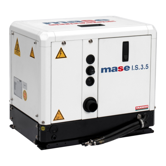
Summary of Contents for Mase Generators IS 3.5
- Page 1 IS 3.5 IS 4.0 IS 5.0 IS 6.0 GB - INSTALLATION MANUAL...
-
Page 2: Table Of Contents
IS 3.5 - 4.0 - 5.0 - 6.0 THE GUARANTEE OF THE PRODUCT BECOMES VOID IF THE SPECIFICATIONS CONTAINED IN THE FOLLOWING INSTALLATION MANUAL ARE NOT RESPECTED INSTALLATION 1.1 Characteristics of the installation space ..... 5 1.2 Fastening the unit to the ground ......5 1.3 Ventilation ............ -
Page 3: Installation
IS 3.5 - 4.0 - 5.0 - 6.0 1.0. INSTALLATION IS 3.5 - 4.0 1.1. Characteristics of the installation space The generator must be installed in a sufficiently aired space, supplying a little amount of air necessary for the combustion of the motor. - Page 4 IS 3.5 - 4.0 - 5.0 - 6.0 MASE recommend the direct infeed system ref. 1 fig. 3 since this system prevents water under pressure entering the suction ducts and instead forms a pressure which can easily be overcome by the water pump of the electric generator.
-
Page 5: Typical Installation With Electric Generator Above The Water-Line
IS 3.5 - 4.0 - 5.0 - 6.0 2.2. Typical installation with electric generator above the water-line (fig. 4) Sea intake • Prise en mer General tap-water • Robinet gènèral de l'eau Tap to drain system • Robinet de vidage de l'installation Water filter •... -
Page 6: Components
IS 3.5 - 4.0 - 5.0 - 6.0 2.4. Components 1 - Direct sea intake 1/2" IMPORTANT If the unit is installed more than 1 metre above the water-line, a check valve should be fitted after the sea intake (fig. 6, ref. 1) to prevent the water circuit emptying when the motor is off. - Page 7 IS 3.5 - 4.0 - 5.0 - 6.0 Diesel return Diesel Fig. 10 - 12 -...
-
Page 8: Battery Connection
IS 3.5 - 4.0 - 5.0 - 6.0 4.0. ELECTRICAL CONNECTIONS 4.1. Battery connection To start off the unit an independent battery of 12V is needed, capacity 18 - 30 Ah min. It should be connected to the clamp of the generator as shown in fig. - Page 9 IS 3.5 - 4.0 - 5.0 - 6.0 4.0. ELECTRICAL CONNECTIONS 4.1. Battery connection To start off the unit an independent battery of 12V is needed, capacity 18 - 30 Ah min. It should be connected to the clamp of the generator as shown in fig.
-
Page 10: Connection
IS 3.5 - 4.0 - 5.0 - 6.0 IMPORTANT The control panel is indispensable for operating the unit and must be installed; do not use devices othet than the control panel supplied with the unit since they might not be compatible with the generator. -
Page 11: Generator - Mains Switching
IS 3.5 - 4.0 - 5.0 - 6.0 - Ensure that the sum of the loads to be supplied does not exceed the nominal power of the electric generator. - Magnetothermic protective devices or similar should be placed between the generator and electrical equipment, according to the tables shown below.


Need help?
Do you have a question about the IS 3.5 and is the answer not in the manual?
Questions and answers