Advertisement
Quick Links
Advertisement

Related Manuals for Mase Generators IS9.5


Summary of Contents for Mase Generators IS9.5
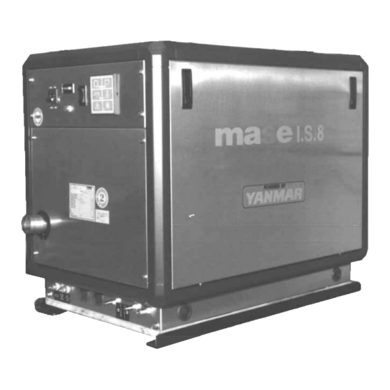
- Page 1 IS9.5 INSTALLATION MANUAL #13501...
- Page 2 32-7/8" 1" 1" 31" Fig. 1 Fig. 2 Fig. 3 Fig. 4...
- Page 3 Fig. 5 Fig. 6 Fig. 6 Fig. 7...
- Page 4 Fig. 9 Fig. 8 Anti-siphon valve Fig. 10 Fig. 11 Fig. 12...
- Page 5 Fig. 13 Fig.14 Fig.15...
- Page 6 GEN. MAIN LOAD Fig. 17 Fig. 16...
- Page 7 Fig. 18...
- Page 8 CONTENTS THE WARRANTY OF THE PRODUCT MAY BE VOIDED IF THE SPECIFICATIONS CONTAINED IN THIS INSTALLATION MANUAL ARE NOT FOLLOWED. INSTALLATION 1.1 Space requirements ......... 14 1.2 Fastening the unit ..........14 1.3 Ventilation ............14 COOLING WATER CIRCUIT 2.1. Raw water feed system ........14 2.2 Typical installation with electric generator above the water-line ..........
-
Page 9: Installation
6 Barrel muffler 2. COOLING WATER CIRCUIT 7 Silencer 8 Exhaust through-hull The engine of generators IS9.5, is cooled by a closed 9 Water line circuit heat exchanger. A - Hose - internal diameter 50 mm (1.96") Upon installation, a raw water feed circuit for cooling and B - Hose - internal diameter 15 mm (.59") - Page 10 4 - Water filter (can be inspected) This must provide sufficient protection for the cooling References for figure 7: circuit from the entrance of mud, sand and seaweed. Intake valve Water pump flow for IS9.5 is 6.6 gal/min. Drain valve Water filter INFORMATION Anti-siphon valve The filter mesh should be very fine.
-
Page 11: Fuel Circuit
remain empty to allow air to pass through when the 4.0 ELECTRICAL CONNECTIONS unit is switched off. (see fig. 9) 4.1. Battery connection It is recommended that the drain hose from the anti-siphon A battery of 12V, 70Ah, is needed to start off the valve be fed into the bilge, as small amounts of water might generator. - Page 12 4.3. A.C. Connection 5. LIFTING This connection is made through the power terminal board (fig.14, ref. 1). Remove the main panel to gain access to To lift the generator, use ONLY the provided lifting points. the terminal strip as shown on fig. 13. This range includes the possibility of use both at 120V DANGER 60Hz and 240V 60Hz.
Need help?
Do you have a question about the IS9.5 and is the answer not in the manual?
Questions and answers