
Related Manuals for Beretta POWER X 50 DEP


Summary of Contents for Beretta POWER X 50 DEP
- Page 1 Manuale Installatore Installation Manual POWER X 35 - 50 - 50 DEP CONDENSAZIONE | CONDENSING Manuale Installatore Installation Manual...
- Page 2 POWER X 35 R.S.I. 20124217 Centro Tecnico di Assistenza , che è specificatamen- POWER X 50 DEP R.S.I. 20117322 te preparato ed addestrato per effettuare la manutenzione POWER X 50 20114814 periodica, potrà...
-
Page 3: Table Of Contents
ITALIANO INDICE AVVERTENZE E SICUREZZE ACCENSIONE E FUNZIONAMENTO Avvertenze generali ..... . . 4 Operazioni preliminari ..... 29 Regole fondamentali di sicurezza. -
Page 4: Avvertenze E Sicurezze
ITALIANO AVVERTENZE E SICUREZZE La linea di collegamento dello scarico condensa deve essere a tenuta garantita e adeguatamente pro- tetta dai rischi di gelo (per es. coibentandola). 1 1 Avvertenze generali Smaltire i materiali di imballaggio nei contenitori ap- propriati presso gli appositi centri di raccolta. Le caldaie prodotte nei nostri stabilimenti vengono I rifiuti devono essere smaltiti senza pericolo per la costruite facendo attenzione anche ai singoli compo-... -
Page 5: Descrizione Dell'apparecchio
ITALIANO È vietato tirare, staccare, torcere i cavi elettrici, fuoriu- Le prescrizioni dettagliate per l’installazione del camino, scenti dall’apparecchio, anche se questo è scollega- delle tubazioni del gas e per la ventilazione del locale, sono to dalla rete di alimentazione elettrica. contenute nelle norma UNI-CIG 7129-7131 e UNI 11071. -
Page 6: Elementi Funzionali Dell'apparecchio
17 Ventilatore 18 Aspirazione aria 19 Scarico fumi 20 Elettrodo di accensione/rilevazione Fig. 1 - POWER X 50 DEP R.S.I. POWER X 50 / 50 R.S.I. 1 Valvola di sfogo aria 2 Separatore acqua/aria 3 Termostato di sicurezza 4 Sonda di mandata... -
Page 7: Dimensioni D'ingombro Ed Attacchi
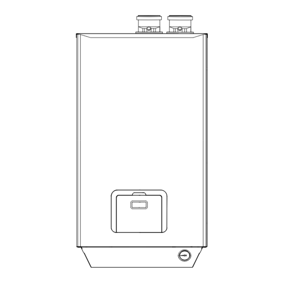
ITALIANO 2 3 Dimensioni d’ingombro ed attacchi Ø80mm Fig. 3 1 Ritorno impianto 2 Mandata impianto 3 Attacco gas 4 Scarico condensa Ø18 5 Uscita valvola 3 vie (solo versioni R.S.I) (vedi capitolo Predisposizione per lo scarico condensa) -
Page 8: Circuito Idraulico
ITALIANO 2 4 Circuito idraulico 2 4 1 Circuito idraulico senza valvola deviatrice interna 1 Scambiatore 2 Circolatore 3 Ventilatore 4 Valvola di sfogo aria 5 Pressostato differenziale/di minima 6 Sonda temperatura fumi 7 Sonda riscaldamento (mandata) 8 Sonda riscaldamento (ritorno) 9 Vaso di espansione interno (opzionale, di serie versioni 35 R.S.I.) 10 Valvola di sicurezza 3,5 bar... -
Page 9: Pannello Di Comando
ITALIANO 2 5 Pannello di comando Fig. 6 Display Tasti di incremento/diminuzione temperatura di riscaldamento Tasto estate/inverno Tasti di incremento/diminuzione temperatura acqua sanitaria Tasto ON/OFF e RESET... -
Page 10: Dati Tecnici
ITALIANO 2 6 Dati tecnici POWER X Descrizione 35 R.S.I. 50 DEP R.S.I. 50 / 50 R.S.I. Omologazioni C13, C13x; C33, C33x; C43, C43x; C53, C53x; Tipologia caldaia C63, C63x; C83, C83x N° certificazione CE 0085AQ0713 Ingombri Altezza x Larghezza x Profondità 915 x 510 x 375 Peso caldaia a vuoto Contenuto d’acqua... -
Page 11: Circolatore
ITALIANO Caratteristiche di efficienza del prodotto: POWER X Descrizione 35 R.S.I. 50 DEP R.S.I. 50 / 50 R.S.I. Portata termica nominale massima 38,6 Portata termica nominale minima Potenza termica nominale massima in sanitario (80-60) Potenza termica nominale minima in sanitario (80-60) Parametro Classe di efficienza Energetica stagionale del riscalda- mento d'ambiente... -
Page 12: Schema Elettrico Multifilare Caldaia
ITALIANO 2 8 Schema elettrico multifilare caldaia Fig. 8 Colore dei cavi: Legenda: bianco rosa accenditore sonda ritorno rosso cavo alimentazione sonda sanitaria giallo verde comando remoto cronotermostato ambiente (opz.) giallo elettrov. gas trasduttore di pressione EV1, EV2 giallo-verde morsettiera termostato di sicurezza arancione circolatore modulante... - Page 13 ITALIANO Tmix T_LIMIT LOW TEMP n n m r r a b c a b c a b c gv gv c m m c 230V Pump 1 Pump 2 1 2 1 3 230AC Vmix Fig. 9 Colore dei cavi: Legenda: bianco verde...
-
Page 14: Installazione
ITALIANO INSTALLAZIONE Per un corretto posizionamento dell’apparecchio inoltre te- nere presente che: - non deve essere posizionato sopra una cucina o altro apparecchio di cottura 3 1 Norme per l'installazione - è vietato lasciare sostanze infiammabili nel locale dov’è installata la caldaia L’installazione dev’essere eseguita da personale qualifica- - le pareti sensibili al calore (per es. -
Page 15: Predisposizioni Per Una Corretta Installazione
ITALIANO 3 2 Predisposizioni per una corretta 3 Alimentare elettricamente la caldaia lasciando chiuso il installazione rubinetto del gas. 4 Attivare una richiesta di calore tramite il termostato am- biente o il pannello comandi a distanza in modo che la Le caratteristiche peculiari della caldaia POWER X garan- valvola tre-vie si posizioni in riscaldamento. -
Page 16: Idraulici
ITALIANO 3 5 Posizionamento della caldaia e Come accessorio sono disponibili telai di supporto per ap- collegamenti idraulici plicazioni a parete e a pavimento. Per il montaggio degli accessori fare riferimento alle istru- zioni contenute a corredo. Prima di effettuare l’installazione verificare di dispor- Effettuare i collegamenti idraulici e provvedere al convo- re degli spazi necessari per la realizzazione dell’im- gliamento dello scarico della valvola di sicurezza e del ru-... -
Page 17: Installazione Sonda Esterna
ITALIANO 3 6 Installazione sonda esterna Il corretto posizionamento della sonda esterna (opziona- le) è fondamentale per il buon funzionamento del controllo climatico. La sonda deve essere installata all’esterno dell’edificio da riscaldare, a circa 2/3 dell’altezza della facciata a NORD o NORD-OVEST e distante da canne fumarie, porte, finestre ed aree assolate. -
Page 18: Collegamenti Elettrici
ITALIANO 3 7 Collegamenti elettrici Particolare attenzione va posta per evitare di invertire i cavi di Fase e Neutro. Prima di collegare la caldaia alla rete elettrica è opportuno: Verificare, inoltre, che i cavi di potenza siano separati da - installare un interruttore differenziale magneto-termi- quelli di comando mediante condotti corrugati in PVC. -
Page 19: Schemi Idraulici
ITALIANO 3 9 Schemi idraulici INSTALLAZIONE CALDAIA SINGOLA Legenda schemi idraulici 11 12 Generatore di calore Pozzetto per sonda valvola intercetta- kit D zione combustibile Termostato di blocco a riarmo manuale kit E omologato INAIL [100(0-6°C)] Pozzetto termometro di prova kit E Termometro omologato INAIL (scala da kit E... - Page 20 ITALIANO POWER X 50 / 50 R.S.I. Kit tronchetto INAIL + Kit INAIL + Kit separatore idraulico 1”F 3/4”F 3/4”M 1 1/2” 1 1/2” 3/4”M 1 1/4”F 100 100 1 1/4”F 126,5 Fig. 16 Kit telaio kit staffa posteriore (applicazione a pavimento) POWER X 50 / 50 R.S.I.
- Page 21 ITALIANO POWER X 50 DEP R.S.I. Kit rubinetti intercettazione impianto + Kit separatore idraulico 1 1/2” 1 1/2” 3/4”M 1 1/4”F 1 1/4”F 126,5 3/4”M 100 100 Fig. 18 POWER X 50 DEP R.S.I. Kit rubinetti intercettazione impianto + Kit separatore idraulico + Kit valvola 3 vie bollitore 1”M...
- Page 22 ITALIANO Schema idraulico impianto solo riscaldamento con circuito opzionale AT o BT Fig. 20 Generatore di calore Vaso d’espansione (opzionale anche interno) Filtro impianto Valvola d’intercettazione impianto Circolatore (230Vac / 50Hz / P<120W) Valvola di non ritorno Termostato di sicurezza con contatto compatibile a bassa tensione e bassa corrente...
- Page 23 ITALIANO Schema idraulico impianto circuito AT e bollitore sanitario (comando con 3 vie) Fig. 21 Generatore di calore Vaso d’espansione (opzionale anche interno) Filtro impianto Valvola d’intercettazione impianto Circolatore (230Vac / 50Hz / P<120W) Valvola di non ritorno Bollitore...
- Page 24 ITALIANO Schema idraulico impianto circuito AT + BT e bollitore sanitario (comando con 3 vie) Fig. 22 Generatore di calore Vaso d’espansione (opzionale anche interno) Filtro impianto Valvola d’intercettazione impianto Circolatore (230Vac / 50Hz / P<120W) Valvola di non ritorno Termostato di sicurezza con contatto compatibile anche con bassa tensione/bassa corrente Valvola miscelatrice (24Vac/ 50Hz / P<50W / 120sec) Sonda circuito BT (NTC 10KΏ@25°C β...
-
Page 25: Evacuazione Dei Prodotti Della Combustione Ed Aspirazione Aria
ITALIANO 3 10 Evacuazione dei prodotti della Non convogliare i fumi di più caldaie all’interno del- combustione ed aspirazione aria lo stesso condotto di scarico, ciascuna di esse deve necessariamente avere un proprio condotto indipen- dente. Si ricorda che se si rendesse necessario pro- Per l’evacuazione dei prodotti combusti riferirsi alla nor- lungare il condotto di scarico oltre i 4 metri, è... - Page 26 ITALIANO Condotti coassiali (ø 60-100 mm) Per poter collegare i condotti coassiali è necessario impie- gare l’adattatore specifico fornito come accessorio. Per lo scarico coassiale posteriore, a parete, è necessario utilizzare il kit telaio distanziale (fare riferimento al Catalo- go). I condotti coassiali possono essere orientati nella direzio- ne più...
-
Page 27: Utilizzo Di Vecchie Canne Fumarie
ITALIANO 3 10 3 Utilizzo di vecchie canne fumarie Non utilizzare in nessun caso tubazioni in rame, poiché l'azione della condensa ne provocherebbe un rapido de- Il condotto di scarico della caldaia POWER X non può es- grado. sere collegato direttamente a canne fumarie esistenti ed utilizzate per altri scopi (cappe cucine, caldaie, ecc). -
Page 28: Riempimento Dell'impianto Di Riscaldamento
ITALIANO 3 10 5 Riempimento dell’impianto di 3 10 6 Svuotamento dell’impianto di riscaldamento riscaldamento Effettuati i collegamenti idraulici, si può procedere al riem- Prima di iniziare lo svuotamento togliere l’alimentazione pimento dell’impianto di riscaldamento. elettrica posizionando l’interruttore generale dell’impianto Questa operazione deve essere eseguita ad impianto fred- su "spento". -
Page 29: Accensione Efunzionamento
ITALIANO ACCENSIONE E FUNZIONAMENTO 4 1 Operazioni preliminari Prima di utilizzare la caldaia, accertarsi che: - Le valvole di intercettazione presenti sulla linea gas Fig. 33 siano aperte. - L’interruttore generale esterno alla caldaia sia acce- Il messaggio " 3_on " sul display indica l’attivazione della modalità... -
Page 30: Regolazione Temperatura Acqua Riscaldamento
ITALIANO Quando la temperatura dell’accumulo scende al di sotto Sia nella modalità ESTATE che INVERNO, se c’è richiesta, del valore impostato sul termostato del bollitore la calda- la caldaia riscalda l’acqua per gli utilizzi domestici. ia commuta la valvola deviatrice verso il circuito sanitario, La temperatura dell’acqua calda può... -
Page 31: Regolazione Con Sonda Climatica Esterna
ITALIANO 4 5 Monitoraggio della caldaia 4 4 2 Regolazione con sonda climatica esterna I due display presenti sul pannello comandi della caldaia La caldaia è predisposta per funzionare con una regolazio- , forniscono all’utente le seguenti informazioni: POWER X ne di tipo climatica grazie all’utilizzo di una sonda esterna - Stato di funzionamento della caldaia, che, una volta installata, viene automaticamente ricono-... -
Page 32: Temperature Impostate Dall'utente
ITALIANO 4 5 2 Temperature impostate dall’utente 4 5 3 Funzione monitor L’utente può impostare le temperature di mandata dell’ac- I due digit di destra del display mostrano normalmente il qua calda per il riscaldamento e per gli utilizzi domestici valore della temperatura letta dell’acqua del riscaldamento (sanitario). -
Page 33: Segnalazione D'errore
ITALIANO 4 5 4 Segnalazione d'errore Tipo Descrizione errore La caldaia è dotata di un sistema di autodiagnosi dei guasti Fiamma rilevata prima dell'apertura della che facilita il manutentore nell’identificare la causa dell’a- A 20 valvola gas. Premere il tasto reset. nomalia. -
Page 34: Regolazioni
- A caldaia accesa premere contemporaneamente, per 5 secondi, i tasti "+" e "-" della regolazione del riscaldamento Fig. 43 - POWER X 50 DEP R.S.I. POWER X 50 / 50 R.S.I. Per 5 secondi Fig. 41 - Sul display comparirà... -
Page 35: Cambio Gas-Trasformazione Metano-Gpl
- Inserire l’apposito diaframma "A" POWER X 35 R.S.I. POWER X 35 R.S.I. Fig. 45 - POWER X 50 DEP R.S.I. POWER X 50 / 50 R.S.I. Fig. 47 - POWER X 50 DEP R.S.I. POWER X 50 / 50 R.S.I. -
Page 36: Manutenzione
ITALIANO MANUTENZIONE - controllo accensione, spegnimento e funzionamento dell’apparecchio sia in sanitario che in riscaldamen- È obbligatorio effettuare almeno una volta all'anno la manu- - controllo tenuta raccordi e tubazioni di collegamento tenzione e la pulizia dell'apparecchio. gas ed acqua; Tale intervento, effettuato dal Centro Tecnico di Assisten- - controllo del consumo di gas alla potenza massima za oppure da personale professionalmente qualificato, è... -
Page 37: Programmazione
ITALIANO PROGRAMMAZIONE Il numero del parametro selezionato apparirà in alternanza con il valore impostato. Nei due digit di destra si potrà vi- sualizzare il valore assunto dal parametro selezionato. - Per entrare in modalità programmazione premere per 4 secondi il Tasto estate/inverno (3). - Premere i Tasti "+"... -
Page 38: Lista Parametri
ITALIANO 6 4 Lista Parametri Limite Limite Valori di N° Descrizione Specifiche inferiore superiore fabbrica Temperatura massima sul riscaldamento sul 1° Temperatura massi- circuito. ma riscaldamento 1° 10°C 80°C 80°C È il valore massimo in funzione climatica sul 1° circuito circuito. - Page 39 ITALIANO Limite Limite Valori di N° Descrizione Specifiche inferiore superiore fabbrica 0 = Funzione climatica non attiva ( anche con la presenza della sonda esterna T4) Modalità riscaldamen- 1 = Funzione climatica attiva con sonda esterna to 1° circuito presente T4 (auto riconoscimento) 2 = Richiesta permanente anche senza T.A.
- Page 40 Arrange for your POWER X 35 R.S.I. 20124217 boiler to be serviced regularly by an authorised Technical POWER X 50 DEP R.S.I. 20117322 Assistance Centre . Their personnel are specially POWER X 50 20114814 trained to keep your boiler efficient and cheap to run.
- Page 41 CONTENTS WARNINGS AND SAFETY IGNITION AND OPERATION General Safety Information ....42 Preliminary operations ....67 Precautions .
-
Page 42: Warnings And Safety
WARNINGS AND SAFETY The seal of the condensate drainage connection line must be guaranteed, and the line must be well pro- tected against the risk of freezing (e.g. by insulating it). 1 1 General Safety Information Dispose of all the packaging materials in the suitable containers at the corresponding collection centres. -
Page 43: Description Of The Appliance
Never pull, disconnect, or twist the electrical cables Detailed regulations for the installation of the flue, gas pip- coming from the appliance even if it is disconnected ing and ventilation ducting are given in Standards UNI-CIG from the mains electricity supply. 7129-7131 and UNI 11071. -
Page 44: Functional Elements Of The Appliance
17 Fan 18 Air inlet 19 Exhaust flue duct 20 Ignition/detection electrode Fig. 1 - POWER X 50 DEP R.S.I. POWER X 50 / 50 R.S.I. 1 Air vent valve 2 Water/air separator 3 Safety thermostat 4 CH flow temperature sensor 5 Exchanger 6 Diff. -
Page 45: Max. Dimensions And Connections
2 3 Max dimensions and connections Ø80mm Fig. 3 1 Central heating return 2 Central heating flow 3 Gas fitting 4 Condensate outlet Ø18 5 3-way valve output (R.S.I. versions only) (see chapter Preparation for the condensate drain) -
Page 46: Water Circuit
2 4 Water circuit 2 4 1 Water circuit without internal diverter valve 1 Exchanger 2 Pump 3 Fan 4 Air vent valve 5 Differential/minimum pressure switch 6 Flue gas temperature probe 7 Heating probe (delivery) 8 Heating probe (return) 9 Internal expansion tank (optional, standard on 35 R.S.I. -
Page 47: Control Panel
2 5 Control panel Fig. 6 Display Heating temperature up/down buttons Summer/winter button Domestic hot water temperature up/down buttons ON/OFF and RESET button... -
Page 48: Technical Specifications
2 6 Technical specifications POWER X Description 35 R.S.I. 50 DEP R.S.I. 50 / 50 R.S.I. Certifications C13, C13x; C33, C33x; C43, C43x; C53, C53x; Boiler typology C63, C63x; C83, C83x CE certification no 0085AQ0713 Encumbrances Height x Width x Depth 915 x 510 x 375 Loadless boiler weight Water capacity... -
Page 49: Pump
Product efficiency characteristics: POWER X Description 35 R.S.I. 50 DEP R.S.I. 50 / 50 R.S.I. Maximum rated heat input 38,6 Minimum rated heat input Domestic hot water maximum rated thermal input (80- Domestic hot water minimum rated thermal input (80- Parameter Seasonal heating energy efficiency class Rated input... -
Page 50: Multi-Row Wiring Diagram
2 8 Multi-row wiring diagram Fig. 8 Cable colours: Key: white pink igniter return probe blue power cable domestic hot water probe yellow green Remote control ambient chronothermostat (opt.) yellow gas solenoid pressure transducer EV1, EV2 yellow-green terminal board safety thermostat orange modulating circulator P1, P2... - Page 51 Tmix T_LIMIT LOW TEMP n n m r r a b c a b c a b c gv gv c m m c 230V Pump 1 Pump 2 1 2 1 3 230AC Vmix Fig. 9 Cable colours: Key: white green high-temperature system pump...
-
Page 52: Installation
INSTALLATION In order to ensure the proper positioning of the appliance, the following points must also be taken into consideration: - - it must not be placed above a cooker or other cook- ing device 3 1 Installation standards - - it is forbidden to leave inflammable products in the room where the boiler is installed The installation must be carried out by qualified personnel, - any heat-sensitive walls (e.g. -
Page 53: Requirements For Proper Installation
3 2 Requirements for proper 3 Switch on the electricity supply to the boiler, leaving the installation gas valve closed. 4 Activate a heat request via the ambient thermostat or the remote control panel, so that the 3-way valve goes The POWER X boiler's particular characteristics guarantee into heating mode. -
Page 54: Positioning The Boiler And Making The Hydraulic Connections
3 5 Positioning the boiler Support frames for wall and floor applications are also available as an accessory. and making the hydraulic In order to install the accessories, please refer to the in- connections structions supplied along with them. Complete the water connections and assemble the drain pipes for the safety valve and the 3-way valve. -
Page 55: Outdoor Sensor Installation
3 6 Outdoor sensor installation The outdoor sensor (optional) must be positioned correctly in order to ensure the climate control's proper functionality. The sensor must be installed outside the building to be heated, at approx. 2/3 the height of the NORTH or NORTH WEST façade and far from flues, doors, windows and sun- ny areas. -
Page 56: Electrical Connections
3 7 Electrical connections Particular caution must be taken to avoid inverting the Phase and Neutral wires. Before connecting the boiler to its electrical power supply, Also make sure that the power cables are separated from it is recommended: the control cables using sections of corrugated PVC pip- - install a thermal magnetic circuit breaker In=10 A ing. -
Page 57: Hydraulic Diagrams
3 9 Hydraulic diagrams SINGLE BOILER INSTALLATION Water circuit schemes legend 11 12 Heat generator Fuel shut-off valve probe pit kit D Lockout thermostat with manual reset, kit E INAIL certified [100(0-6°C)] Sump for test thermometer kit E Thermometer, INAIL certified (scale kit E from 0 to 120°C) Safety valve, INAIL certified (3.5 bar) - Page 58 POWER X 50 / 50 R.S.I. INAIL connection Kit + INAIL Kit + water separator Kit 1”F 3/4”F 3/4”M 1 1/2” 1 1/2” 3/4”M 1 1/4”F 100 100 1 1/4”F 126,5 Fig. 16 Frame kit rear bracket kit (floor application) POWER X 50 / 50 R.S.I.
- Page 59 POWER X 50 DEP R.S.I. System shut-off valves kit + Hydraulic separator kit 1 1/2” 1 1/2” 3/4”M 1 1/4”F 1 1/4”F 126,5 3/4”M 100 100 Fig. 18 POWER X 50 DEP R.S.I. System shut-off valves kit + Hydraulic separator kit + Storage tank 3-way valve kit 1”M...
- Page 60 Water scheme for heating-only system with optional HT or LT circuit Fig. 20 Heat generator Expansion vessel (indoor also available as an option) System filter System shut-off valve Circulator (230Vac / 50Hz / P<120W) Non-return valve Safety thermostat with contact compatible at low voltage and low current...
- Page 61 Water scheme for HT circuit system and domestic water storage tank (3-way command) Fig. 21 Heat generator Expansion vessel (indoor also available as an option) System filter System shut-off valve Circulator (230Vac / 50Hz / P<120W) Non-return valve Storage cylinder...
- Page 62 Water scheme for HT + LT circuit system and domestic water storage tank (3-way command) Fig. 22 Heat generator Expansion vessel (indoor also available as an option) System filter System shut-off valve Circulator (230Vac / 50Hz / P<120W) Non-return valve Safety thermostat with contact even compatible with low voltage/low current Mixer valve (24VAC/ 50Hz / P<50W / 120sec) BT circuit probe (NTC 10KΏ@25°C β...
-
Page 63: Suction
3 10 Evacuation of combustion Do not convey the flue gases from multiple boilers into the same discharge pipe; each must have its products and air suction own independent pipe. If the discharge pipe needs to be extended beyond 4 metres, it is recommend- For flue gas discharge, refer to Standards UNI-CIG 7129- ed to install a siphon at the base of the vertical tract, 7131 and UNI 11071. - Page 64 Concentric pipes (ø 60-100mm) To connect the concentric pipes, use the specific adaptor supplied as an accessory. The frame spacer kit must be utilized for the wall-mounted rear concentric discharge (see the Catalogue). The concentric pipes can face in the direction most suit- able for installation requirements, but special attention should be paid to the external temperature and the length of the pipe.
-
Page 65: Use Of Old Flue Pipes
3 10 3 Use of old flue pipes Never use copper pipes under any circumstances, as the condensate itself will cause them to rapidly deteriorate. The POWER X boiler's discharge pipe cannot be connected directly to any pre-existing flue pipes utilized for other pur- poses (kitchen hoods, boilers, etc.). -
Page 66: Filling The Heating System
3 10 5 Filling the heating system 3 10 6 Emptying the heating system Once the hydraulic connections have been carried out, fill Before emptying the system, always remember to shut-off the heating system. the electrical power supply by setting the system's main This operation must be carried out with a cold system, fol- switch to its "off"... -
Page 67: Ignition And Operation
IGNITION AND OPERATION 4 1 Preliminary operations Before using the boiler, make sure that: - The shutoff valves on the gas line are open. - The boiler's external main switch is on. Fig. 33 - The water circuit has been filled. If this is not the case, fill the system according to the instructions provided in the section "Filling the heating system". -
Page 68: Heating Water Temperature Adjustment
When the storage temperature drops below the set value The boiler heats water for domestic hot water purposes on the storage tank's thermostat, the boiler switches the whenever required, in both SUMMER and WINTER mode. diverter valve towards the hot water circuit, activates the The temperature of the hot water can be adjusted by the circulator, and ignites the burner to meet the storage tank's user by pressing the "+"... -
Page 69: Probe
4 5 Monitoring the boiler 4 4 2 Adjustment with an external climate control probe The two displays on the boiler's control panel POWER X The boiler is predisposed for climate control functionality provide the user with the following information: thanks to the use of an external probe, which, once in- - The boiler's operating status, stalled, is automatically recognized by the boiler's elec-... -
Page 70: Temperatures Set By The User
4 5 2 Temperatures set by the user 4 5 3 Monitor function The user can set the hot water delivery temperatures for The two digits on the right-hand side of the display nor- both the heating and domestic hot water circuits. mally show the current temperature value of the water in In order to view the set heating temperature value, simply the heating circuit, or else that of the domestic hot water... -
Page 71: Error Messages
4 5 4 Error messages Error Description type The boiler is equipped with a self-diagnostics system in or- Flame detected before the opening of the gas der to help the maintenance personnel identify the causes valve. Press the reset key. of any anomalies. -
Page 72: Adjustments
- With the boiler on, simultaneously press the heating function's "+" and "-" buttons for 5 seconds 5 seconds Fig. 43 - POWER X 50 DEP R.S.I. POWER X 50 / 50 R.S.I. Fig. 41 - The letter "t" will appear on the display, and the boiler will set itself to "TEST"... -
Page 73: Changing Gas - Methane-Lpg Transformation
- Insert the appropriate "A" diaphragm POWER X 35 R.S.I. POWER X 35 R.S.I. Fig. 45 - POWER X 50 DEP R.S.I. POWER X 50 / 50 R.S.I. Fig. 47 - POWER X 50 DEP R.S.I. POWER X 50 / 50 R.S.I. -
Page 74: Maintenance
MAINTENANCE - checking the ignition, switch-off and operation of the appliance, in both domestic water mode and heating mode It is mandatory to perform maintenance and cleaning of the - checking the seal on the gas and water couplings device at least once a year. and pipes This operation, carried out by Technical Assistance Cen- - checking the gas consumption at maximum and min-... -
Page 75: Programming
PROGRAMMING The selected parameter number will appear in alternation with the set value. The value assigned to the selected pa- rameter is shown in the two digits on the right. - In order to access programming mode, press the summer/winter Button (3) for 4 seconds. - Press the "+"... -
Page 76: Parameter List
6 4 Parameter List Lower Upper Default Description Specifications limit limit values Maximum heating temperature on the 1st circuit. 1st circuit maximum 10°C 80°C 80°C This is the maximum value for the 1st circuit in heating temperature climate control mode. 1st circuit minimum heating temperature. - Page 77 Lower Upper Default Description Specifications limit limit values 0 = Climate control function not enabled (even with the T4 outdoor sensor present) 1st circuit heating 1 = Climate control function enabled with the T4 mode outdoor sensor present (automatic detection) 2 = Permanent request even without T.A.
- Page 80 Via Risorgimento, 23 A 23900 - Lecco (LC) www.berettaclima.it Poiché l’Azienda è costantemente impegnata nel continuo perfezionamento di tutta la sua produzione, le caratteristiche estetiche e dimensionali, i dati tecnici, gli equipaggiamenti e gli accessori, possono essere soggetti a variazione. www.berettaboilers.com The manufacturer strives to continuously improve all products.
Need help?
Do you have a question about the POWER X 50 DEP and is the answer not in the manual?
Questions and answers