Table of Contents
Advertisement
Quick Links
Advertisement
Table of Contents

Subscribe to Our Youtube Channel
Related Manuals for Metrohm 930 Compact IC Flex Oven/ChS


Summary of Contents for Metrohm 930 Compact IC Flex Oven/ChS
- Page 1 930 Compact IC Flex 930 Compact IC Flex Oven/ChS Manual 8.930.8013EN / 2017-07-31...
- Page 3 Metrohm AG CH-9100 Herisau Switzerland Phone +41 71 353 85 85 Fax +41 71 353 89 01 info@metrohm.com www.metrohm.com 930 Compact IC Flex 930 Compact IC Flex Oven/ChS 2.930.2200 Manual 8.930.8013EN / 2017-07-31...
- Page 4 Technical Communication Metrohm AG CH-9100 Herisau techcom@metrohm.com This documentation is protected by copyright. All rights reserved. This documentation has been prepared with great care. However, errors can never be entirely ruled out. Please send comments regarding possible errors to the address above.
-
Page 5: Table Of Contents
3.10 Injection valve ..............26 3.11 Metrohm Suppressor Module (MSM) ....... 28 3.11.1 Inserting the rotors ..............29 3.11.2 Connecting the Metrohm Suppressor Module (MSM) ..... 32 3.12 Installing the conductivity detector ........36 ■■■■■■■■ 930 Compact IC Flex Oven/ChS (2.930.2200) - Page 6 Separating efficiency .............. 83 5.14.2 Protecting the separation column .......... 83 5.14.3 Storing the separation column ..........83 5.14.4 Regenerating the separation column ........83 5.15 Quality management and qualification with Metrohm ... 84 ■■■■■■■■ 930 Compact IC Flex Oven/ChS (2.930.2200)
- Page 7 Weight ................. 90 Leak sensor ................. 90 Column oven ............... 90 High-pressure pump ............91 Injection valve ..............92 7.10 Metrohm Suppressor Module (MSM) ....... 92 7.11 Detector ................92 7.12 Power connection ............... 92 7.13 Interfaces ................93 8 Accessories Index ■■■■■■■■...
- Page 8 Figure 11 Pulsation absorber ................26 Figure 12 Exchanging the sample loop ............27 Figure 13 Metrohm Suppressor Module (MSM) – Connection capillaries ..32 Figure 14 Column oven .................. 53 Figure 15 High-pressure pump – Parts ............. 56 Figure 16 High-pressure pump –...
-
Page 9: Introduction
The software controls and monitors the instrument, evaluates the measured data and manages it in a data- base. The 930 Compact IC Flex Oven/ChS consists of the following modules: Housing The sturdy housing contains the instrument's electronic components, including their interfaces and one connector for a separation column. - Page 10 The rotor required for the application and any adapter that is required must be ordered separately. Detector Metrohm offers a series of different detectors for various analysis tasks. A suitable detector type must be ordered as a separate device. Separation column The intelligent separation column separates different components accord- ing to their interactions with the column.
-
Page 11: Intended Use
■■■■■■■■■■■■■■■■■■■■■■ 1 Introduction Intended use The 930 Compact IC Flex Oven/ChS is used for the determination of anions or polar substances with chemical suppression using ion chroma- tography. It can also be used as needed for the determination of cations, polar sub- stances or anions without chemical suppression. -
Page 12: Tubing And Capillary Connections
Damaged tubing ends lead to leakage. Appropriate tools can be used to loosen connections. Check the connections regularly for leakage. If the instrument is used mainly in unattended operation, then weekly inspections are manda- tory. ■■■■■■■■ 930 Compact IC Flex Oven/ChS (2.930.2200) -
Page 13: Flammable Solvents And Chemicals
Method Dialog text, parameter in the software File ▶ New Menu or menu item [Next] Button or key WARNING This symbol draws attention to a possible life-threat- ening hazard or risk of injury. ■■■■■■■■ 930 Compact IC Flex Oven/ChS (2.930.2200) - Page 14 WARNING This symbol draws attention to a possible biological hazard. CAUTION This symbol draws attention to possible damage to instruments or instrument parts. NOTE This symbol highlights additional information and tips. ■■■■■■■■ 930 Compact IC Flex Oven/ChS (2.930.2200)
-
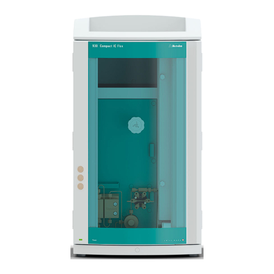
Page 15: Overview Of The Instrument
Offers space for the eluent bottle and addi- For hanging the separation column (iCol- tional accessories. umn). With column recognition. Column oven Metrohm Suppressor Module (MSM) Inline filter Injection valve Pulsation absorber Base tray With leak sensor. ■■■■■■■■ 930 Compact IC Flex Oven/ChS (2.930.2200) -
Page 16: Rear
11 Detector chamber Offers space for an embedded detector and additional accessories. Rear Figure 2 Rear Bottle holder Drainage tubing connection For connecting the drainage tubing, which guides escaped fluids away from the bottle holder. ■■■■■■■■ 930 Compact IC Flex Oven/ChS (2.930.2200) - Page 17 For connecting the instrument to the com- USB devices. puter with the USB cable (6.2151.020). 19 Power socket Power socket for connecting the power cable and power switch for switching the instrument on and off. ■■■■■■■■ 930 Compact IC Flex Oven/ChS (2.930.2200)
-
Page 18: Feed-Throughs For Capillaries And Cables
The two Luer connections above are not actually openings; the capillaries are fastened to the Luer connection from within using PEEK pressure screws. You can use a syringe to inject or draw out liquid from the out- side. ■■■■■■■■ 930 Compact IC Flex Oven/ChS (2.930.2200) -
Page 19: Figure 4 Openings For Capillaries And Cables
The capillaries can be fed to the front of the instrument from both sides of the instrument and from the front of the instrument to the back of the instrument. ■■■■■■■■ 930 Compact IC Flex Oven/ChS (2.930.2200) -
Page 20: Figure 5 Ducts For Capillaries
■■■■■■■■■■■■■■■■■■■■■■ 2.3 Feed-throughs for capillaries and cables Figure 5 Ducts for capillaries ■■■■■■■■ 930 Compact IC Flex Oven/ChS (2.930.2200) -
Page 21: Installation
High-pressure pump, purge valve, inline filter, pulsation absorber, separation columns 6.2744.090 Pressure screw, long MCS, sample degasser, 10- port valve Pressure screws are tightened and loosened by hand. A tool is not nee- ded. ■■■■■■■■ 930 Compact IC Flex Oven/ChS (2.930.2200) - Page 22 (6.2739.000). ■ In order to achieve optimum analysis results, capillary connections in an IC system must be absolutely tight and free of dead volume. Dead volume ■■■■■■■■ 930 Compact IC Flex Oven/ChS (2.930.2200)
- Page 23 2 Heat the colored sleeve, e.g. with a hairdryer. The colored sleeve shrinks and adapts to the shape of the capillary. NOTE In order to arrange capillaries more clearly, they can be bundled with the spiral band (6.1815.010). ■■■■■■■■ 930 Compact IC Flex Oven/ChS (2.930.2200)
-
Page 24: Removing Transport Locking Screws
For the vacuum pump. Only present if the For the high-pressure pump. instrument has a degasser or a CO Suppres- sor (MCS). 1 Remove all of the transport locking screws with the hex key. ■■■■■■■■ 930 Compact IC Flex Oven/ChS (2.930.2200) -
Page 25: Connecting The Drainage Tubing And Leak Sensor
Accessories For this step you need the following parts from the accessory kit: Vario/ Flex Basic (6.5000.000): 2 × silicone tubing (6.1816.020) ■ Y connector (6.1807.010) ■ You also need scissors. ■■■■■■■■ 930 Compact IC Flex Oven/ChS (2.930.2200) - Page 26 Attach the loose end to the right-side drainage tubing connection on the base tray. 6 Attach one end of the second piece of silicone tubing to the left-side drainage tubing connection on the base tray. ■■■■■■■■ 930 Compact IC Flex Oven/ChS (2.930.2200)
-
Page 27: Connecting The Leak Sensor
The temperature of the column oven can be configured in the software. The column oven is completely connected. No installation work is required. ■■■■■■■■ 930 Compact IC Flex Oven/ChS (2.930.2200) -
Page 28: Connecting The Eluent Bottle
Push the loose end of the eluent aspiration tubing through the ■ M8 opening of the bottle cap and screw it on for the time being. Figure 7 Installing the eluent bottle cap ■■■■■■■■ 930 Compact IC Flex Oven/ChS (2.930.2200) - Page 29 Place the loose end of the eluent aspiration tubing into the aspira- ■ tion filter. The end of the tubing should reach approximately to the center of the aspiration filter. Tighten the aspiration filter to the filter holder. ■ ■■■■■■■■ 930 Compact IC Flex Oven/ChS (2.930.2200)
-
Page 30: Figure 8 Installing Tubing Weighting And Aspiration Filter
Then fix it in place using the M8 tubing nipple. Seal the M6 opening on the bottle cap with the M6 threaded ■ stopper from the accessory set. ■■■■■■■■ 930 Compact IC Flex Oven/ChS (2.930.2200) - Page 31 Fill the adsorber tube and close it again using the plastic cover. Insert the adsorber tube into the bottle cap's large opening. Fas- ■ ten it to the bottle cap using the SGJ clip (6.2023.020). ■■■■■■■■ 930 Compact IC Flex Oven/ChS (2.930.2200)
-
Page 32: Installing The High-Pressure Pump
■ The purge valve used for bleeding the pump head. ■ Figure 9 High-pressure pump with purge valve Pump head Purge valve The high-pressure pump is completely connected. No installation work is required. ■■■■■■■■ 930 Compact IC Flex Oven/ChS (2.930.2200) -
Page 33: Installing An Inline Filter
The pulsation absorber is installed between the high-pressure pump and the injection valve. It protects the separation column from damage caused by pressure fluctuations, e.g. when the injection valve is switched, and reduces interfering pulsations during highly sensitive measurements. ■■■■■■■■ 930 Compact IC Flex Oven/ChS (2.930.2200) -
Page 34: Injection Valve
The quantity of sample solution injected is determined by: the volume of the sample loop or ■ by an 800 Dosino when the Metrohm intelligent Partial Loop Injection ■ Technique (MiPT) is used. The choice of sample loop depends on the application. The following... -
Page 35: Figure 12 Exchanging The Sample Loop
Only use PEEK pressure screws (6.2744.010) to connect capillaries and the sample loop to the injection valve. Figure 12 Exchanging the sample loop Pressure screw Sample loop Fastened to Port 6. Pressure screw Fastened to Port 3. ■■■■■■■■ 930 Compact IC Flex Oven/ChS (2.930.2200) -
Page 36: Metrohm Suppressor Module (Msm)
Rotor A (6.2844.000), must first be fitted into the adapter (6.2842.020), which can then be inserted into the suppressor housing. A connecting piece (6.2835.010) is used for all rotors for connecting the Metrohm Suppressor Module (MSM) to the IC system. ■■■■■■■■ 930 Compact IC Flex Oven/ChS (2.930.2200) -
Page 37: Inserting The Rotors
■ Connecting piece (6.2835.010) ■ Large rotors can be inserted directly into the rotor housing. CAUTION The rotor may be destroyed during start-up if not inserted correctly. Therefore, follow the following instructions exactly. ■■■■■■■■ 930 Compact IC Flex Oven/ChS (2.930.2200) - Page 38 If this is not the case, then the rotor must be moved into the cor- rect position using careful turning. If the rotor cannot be turned or removed, it can be moved into the correct position from below by means of a pointed object (e.g. a screwdriver). ■■■■■■■■ 930 Compact IC Flex Oven/ChS (2.930.2200)
- Page 39 2 Inserting the adapter Insert the adapter into the suppressor drive just like a large rotor (see "Inserting large rotors", page 30). ■■■■■■■■ 930 Compact IC Flex Oven/ChS (2.930.2200)
-
Page 40: Connecting The Metrohm Suppressor Module (Msm)
The three entries and exits of the suppressor units, numbered 1, 2 and 3 on the connecting piece, each have two permanently installed PTFE capil- laries. Figure 13 Metrohm Suppressor Module (MSM) – Connection capillaries Outlet capillary for the eluent. Inlet capillary for the eluent. regenerant waste reg. - Page 41 To connect the bottles of the auxiliary solutions, you will need the follow- ing accessories: Accessories from the accessory kit: IC Vario/Flex ChS (6.5000.030) ■ Accessories from IC equipment: Dosino Regeneration (6.5330.190) ■ ■■■■■■■■ 930 Compact IC Flex Oven/ChS (2.930.2200)
- Page 42 1 Connect the capillary labeled regenerant to the outlet of the inline fil- ter (6.2821.120) using a pressure screw (6.2744.070). 2 Use a pressure screw (6.2744.070) to fasten a piece of the PTFE capillary (6.1803.030) to the inlet of the inline filter. ■■■■■■■■ 930 Compact IC Flex Oven/ChS (2.930.2200)
- Page 43 4 Connect the FEP tubing (6.1805.120) from the bottle with the regen- eration solution to Port 2 of the Dosino. 3.11.2.4 Connecting the rinsing solution Various possibilities exist for rinsing the Metrohm Suppressor Module: Rinsing solution via STREAM (recommended) ■ Use the eluent from the conductivity detector as rinsing solution.
-
Page 44: Installing The Conductivity Detector
The detector is available as separate device and is supplied with a separate manual. Placing the detector in the instrument Follow the instructions in the chapter Inserting the detector in the manual for the detector. ■■■■■■■■ 930 Compact IC Flex Oven/ChS (2.930.2200) -
Page 45: Installing The Amperometric Detector
The separation column is not inserted into the instrument until it is being started up for the first time. Until then, the detector inlet capillary has to be connected to the out capillary of the Metrohm Suppressor Module (MSM) using a coupling (6.2744.040). -
Page 46: Connecting The Instrument To A Computer
Basic (6.5000.000) Connecting the USB cable 1 Insert the USB cable into the computer connection socket on the rear of the instrument. 2 Insert the other end into a USB port on the computer. ■■■■■■■■ 930 Compact IC Flex Oven/ChS (2.930.2200) -
Page 47: Connecting The Instrument To The Power Grid
Unplug the power plug immediately if you suspect that moisture has ■ gotten inside the instrument. Only personnel who have been issued Metrohm qualification may ■ perform service and repair work on electrical and electronic parts. Connecting the power cord Accessories Power cord, three-core with IEC 60320 instrument plug type C13. -
Page 48: Initial Start-Up
Check whether the detector outlet capillary is connected to the Metrohm Suppressor Module (MSM)'s inlet capillary for rinsing solu- tion (labeled rinsing solution). - Page 49 Remove the syringe from the purge needle. ■ Pull the purge needle out of the purge capillary. ■ 5 Rinsing the instrument without columns Rinse the instrument (without columns) with eluent for 10 ■ minutes. ■■■■■■■■ 930 Compact IC Flex Oven/ChS (2.930.2200)
-
Page 50: Connecting And Rinsing The Guard Column
Connecting and rinsing the guard column Guard columns protect separation columns and significantly increase their service life. The guard columns available from Metrohm are either actual guard columns or guard column cartridges used together with a cartridge holder. The process of installing a guard column cartridge into the corre- sponding holder is described in the guard column leaflet. - Page 51 Rinsing the guard column 1 Rinsing the guard column Place a beaker under the guard column's outlet. ■ ■■■■■■■■ 930 Compact IC Flex Oven/ChS (2.930.2200)
-
Page 52: Connecting The Separation Column
NOTE Information regarding which separation column is suitable for your application can be found in the Metrohm Column Program, the product information for the separation column or it can be obtained through your representative. - Page 53 ■■■■■■■■■■■■■■■■■■■■■■ 3 Installation NOTE Connect the separation column only after the initial start-up of the instrument. Until that point, insert a coupling (6.2744.040) instead of the guard column and separation column. ■■■■■■■■ 930 Compact IC Flex Oven/ChS (2.930.2200)
- Page 54 Remove the coupling (6.2744.040) from the column outlet capil- ■ lary. 5 Installing the outlet of the separation column Fasten the column outlet capillary to the column outlet using a ■ short PEEK pressure screw (6.2744.070). ■■■■■■■■ 930 Compact IC Flex Oven/ChS (2.930.2200)
-
Page 55: Conditioning
(arrow has to point in the direction of flow). Ensure that the eluent aspiration tubing is immersed in the eluent ■ and that there is enough eluent in the eluent bottle. ■■■■■■■■ 930 Compact IC Flex Oven/ChS (2.930.2200) - Page 56 4 Conditioning the system Continue rinsing the system with eluent until the desired stability level for the baseline has been attained . The instrument is now ready for measuring samples. ■■■■■■■■ 930 Compact IC Flex Oven/ChS (2.930.2200)
-
Page 57: Operation
■■■■■■■■■■■■■■■■■■■■■■ 4 Operation 4 Operation The 930 Compact IC Flex Oven/ChS is operated solely using the MagIC Net software. You can find information on operating the software in the tutorial for MagIC Net or in the online help. ■■■■■■■■ 930 Compact IC Flex Oven/ChS (2.930.2200) -
Page 58: Operation And Maintenance
Maintenance by Metrohm Service Maintenance of the instrument is best carried out as part of an annual service performed by specialist personnel from Metrohm. A shorter main- tenance interval is recommended if you frequently work with caustic and corrosive chemicals. Metrohm Service offers every form of technical advice for maintenance and service of all Metrohm instruments. -
Page 59: Shutting Down And Recommissioning
3 Rinse the IC system for 15 minutes with methanol/ultrapure water mixture (1:4). 4 Optional: Only if the IC system is equipped with a suppressor. In the software, switch the Metrohm Suppressor Module (MSM) twice during the rinsing process at five-minute intervals in each case (STEP command). -
Page 60: Capillary Connections
Column oven – Replacing the capillaries There are preheating grooves in the inner side wall of the column oven, where the column inlet capillary has already been inserted and fastened in place with a holder plate. ■■■■■■■■ 930 Compact IC Flex Oven/ChS (2.930.2200) -
Page 61: Figure 14 Column Oven
For hanging the separation column (iCol- umn). With column recognition. Preheating grooves Holder plate For threading in the capillary to be tempera- For securing the capillary in place. ture-conditioned. Recesses Prevent the capillaries from being pinched. ■■■■■■■■ 930 Compact IC Flex Oven/ChS (2.930.2200) -
Page 62: Handling The Eluent
"p.a.". They may be diluted only by using ultrapure water (resistance > 18.2 MΩ*cm). (These specifications apply generally for all reagents used in ion chromatography.) Newly manufactured eluents always need to be microfiltered (0.45 µm fil- ter). ■■■■■■■■ 930 Compact IC Flex Oven/ChS (2.930.2200) -
Page 63: Changing The Eluent
To protect the high-pressure pump from foreign particles, we recom- ■ mend filtering the eluent through a filter with a pore size of 0.45 µm and aspirating it via an aspiration filter (6.2821.090). ■■■■■■■■ 930 Compact IC Flex Oven/ChS (2.930.2200) -
Page 64: Servicing The High-Pressure Pump
Servicing the high-pressure pump NOTE You can find a video sequence for this task in the Multimedia Guide IC Maintenance or on the Internet at http://ic-help.metrohm.com/. Figure 15 High-pressure pump – Parts Pressure screw, short (6.2744.070) Outlet valve holder Fastened to the outlet valve holder. - Page 65 Internet at http://ic-help.metrohm.com/. Servicing the outlet valve and inlet valve Accessories For this step, you need the following accessories: You can find these parts in the accessory kit: Vario/Flex Basic (6.5000.000). Adjustable wrench (6.2621.000) ■ ■■■■■■■■ 930 Compact IC Flex Oven/ChS (2.930.2200)
- Page 66 RBS™ solution or acetone. The rinsing solution may only come out at the valve outlet. The outlet valve must be replaced if it is still clogged after cleaning. ■■■■■■■■ 930 Compact IC Flex Oven/ChS (2.930.2200)
- Page 67 ¼ turn using the adjustable wrench (3). Tighten the connection capillary to the auxiliary piston back onto ■ the outlet valve holder. ■■■■■■■■ 930 Compact IC Flex Oven/ChS (2.930.2200)
- Page 68 RBS™ solution or acetone. The rinsing solution may only come out at the valve outlet. The inlet valve must be replaced if it is still clogged after cleaning. ■■■■■■■■ 930 Compact IC Flex Oven/ChS (2.930.2200)
- Page 69 You can find these parts in the accessory kit: Vario/Flex Basic (6.5000.000). 4 mm hex key (6.2621.030) ■ Removing the pump head Prerequisites: Is the high-pressure pump switched off? ■ Has the pressure been released? ■ Is the instrument switched off? ■ ■■■■■■■■ 930 Compact IC Flex Oven/ChS (2.930.2200)
- Page 70 Servicing the piston Carry out the following work on both pistons in turn. Servicing a piston consists of the following tasks: Replace the piston seal. Clean or replace the zirconium oxide piston. Reinstall the piston. ■■■■■■■■ 930 Compact IC Flex Oven/ChS (2.930.2200)
-
Page 71: Figure 16 High-Pressure Pump - Cross-Section
(6.5000.000). Adjustable wrench (6.2621.000) ■ Tool for piston seals (6.2617.010) consisting of a tip (17-1) for remov- ■ ing the old piston seal and a sleeve (17-2) for inserting the new piston seal. ■■■■■■■■ 930 Compact IC Flex Oven/ChS (2.930.2200) -
Page 72: Figure 17 Tool For Piston Seal (6.2617.010)
Loosen the piston cartridge (18-1) using the adjustable wrench and then unscrew it from the pump head by hand. Set it aside. 2 Removing the backup ring Shake the backup ring (18-2) out of the piston opening. Set it aside. ■■■■■■■■ 930 Compact IC Flex Oven/ChS (2.930.2200) -
Page 73: Figure 19 Inserting The Piston Seal Into The Tool
Press the seal into the pump head recess using the wide end of the tip (17-1) of the tool. Cleaning or replacing the zirconium oxide piston Prerequisites: ■■■■■■■■ 930 Compact IC Flex Oven/ChS (2.930.2200) -
Page 74: Figure 20 Parts Of The Piston Cartridge
Place the backup ring you put aside with the remaining parts. ■ Figure 20 Parts of the piston cartridge Piston cartridge screw Retaining washer Zirconium oxide piston (6.2824.070) Spring retainer Spring (6.2824.060) Inner plastic sleeve Protects from metallic abrasion. Piston cartridge Backup ring ■■■■■■■■ 930 Compact IC Flex Oven/ChS (2.930.2200) - Page 75 Clean the second piston cartridge in the same way. Mounting the pump head Accessories For this step, you need the following accessories: You can find these parts in the accessory kit: Vario/Flex Basic (6.5000.000). ■■■■■■■■ 930 Compact IC Flex Oven/ChS (2.930.2200)
- Page 76 The bore hole with the greatest depth must therefore be aligned with the longest bolt. Push the pump head onto the four fastening bolts (1). ■ Tighten the four fastening screws using the hex key (6.2621.030) ■ alternating crosswise. ■■■■■■■■ 930 Compact IC Flex Oven/ChS (2.930.2200)
-
Page 77: Servicing The Inline Filter
Servicing the inline filter NOTE You can find a video sequence for this task in the Multimedia Guide IC Maintenance or on the Internet at http://ic-help.metrohm.com/. Maintenance interval The filter must be replaced at least every 3 months; it may need to be replaced more frequently, depending on the application. -
Page 78: Figure 21 Inline Filter - Removing The Filter
3 Unscrewing the filter screw Use two adjustable wrenches (6.2621.000) to loosen the filter screw (21-2) from the filter housing (21-1) and unscrew it by hand. 4 Removing the filter Remove the old filter (21-3) using tweezers. ■■■■■■■■ 930 Compact IC Flex Oven/ChS (2.930.2200) - Page 79 4 Rinsing the inline filter Dismantle the guard column (if present) and the separation col- ■ umn and replace with a coupling (6.2744.040). Rinse the instrument with eluent. ■ Reinsert the columns after 10 minutes. ■ ■■■■■■■■ 930 Compact IC Flex Oven/ChS (2.930.2200)
-
Page 80: Servicing The Pulsation Absorber
If the Metrohm Suppressor Module (MSM) is in a dry state, it must be rinsed for at least five minutes before it may be switched over. -
Page 81: Taking Care Of The Suppressor Housing
■■■■■■■■■■■■■■■■■■■■■■ 5 Operation and maintenance CAUTION The Metrohm Suppressor Module (MSM) must be regenerated (see Chapter 5.11.3.2, page 74), cleaned (see Chapter 5.11.3.4, page 76) or replaced (see Chapter 5.11.3.5, page 79) if the capacity of the Met- rohm Suppressor Module (MSM) is reduced or if the back pressure is high. - Page 82 Pump tubing made of PVC must not be used for solutions containing organic solvents. We recommend using the high-pressure pump for regeneration. Regenerating the anion suppressor rotor 1 Disconnecting the Metrohm Suppressor Module (MSM) from the IC system Disconnect the capillaries of the MSM labeled regenerant and ■...
- Page 83 As soon as all three suppressor units have been rinsed, disconnect ■ the capillary labeled rinsing solution from the coupling. 4 Connecting the Metrohm Suppressor Module (MSM) to the IC system Reconnect the capillaries of the MSM labeled regenerant and ■...
- Page 84 Equilibrate the system as usual (see chapter "Conditioning" in the manual for the ion chromatograph). 5.11.3.4 Cleaning the Metrohm Suppressor Module (MSM) In the following cases, it may be necessary to clean the Metrohm Suppres- sor Module (MSM): Increased back pressure at the MSM's connection tubing. ■ ■■■■■■■■...
- Page 85 Check whether water comes out at the connecting piece. ■ If one of the capillaries remains blocked, the connecting piece (see "Replacing parts of the Metrohm Suppressor Module (MSM)", page 79) must be replaced (order number 6.2835.010). 4 Cleaning the rotor Clean the sealing surface of the rotor (22-3) with ethanol using a ■...
- Page 86 Reattach the union nut (22-1) and tighten by hand (do not use a ■ tool). 8 Connecting and conditioning the Metrohm Suppressor Mod- ule (MSM) Reconnect the MSM to the IC system. ■...
- Page 87 5 Operation and maintenance 5.11.3.5 Replacing parts of the Metrohm Suppressor Module (MSM) Parts of the Metrohm Suppressor Module (MSM) may need to be replaced in the following cases: Irremediable loss of suppressor capacity (reduced phosphate sensitivity ■ and/or significant rise in the baseline).
- Page 88 1 is on top and the three pins of the connecting piece fit into the corresponding recesses on the housing. Reattach the union nut (22-1) and tighten by hand (do not use a ■ tool). ■■■■■■■■ 930 Compact IC Flex Oven/ChS (2.930.2200)
-
Page 89: Servicing The Detector
■■■■■■■■■■■■■■■■■■■■■■ 5 Operation and maintenance 7 Connecting and conditioning the Metrohm Suppressor Mod- ule (MSM) Reconnect all capillaries of the MSM to the IC system. ■ Before switching the MSM over for the first time, rinse the three ■ suppressor units with solution for five minutes. - Page 90 A. The smaller this ratio, the smaller the amount of sample carry- over. This ratio can be changed by varying the rinsing time. This can be used to determine the required rinsing time for the application. ■■■■■■■■ 930 Compact IC Flex Oven/ChS (2.930.2200)
-
Page 91: Separation Column
You can find detailed information on the separation columns available from Metrohm in the leaflet provided along with your separation column, in the Metrohm IC Column Program (available from your Metrohm representative) or on the Internet at http://www.metrohm.com... -
Page 92: Quality Management And Qualification With Metrohm
Metrohm offers you comprehensive support in implementing quality man- agement measures for instruments and software. Qualification Please contact your local Metrohm representative for support in qualifica- tion of instruments and software. The Installation Qualification (IQ) and Operational Qualification (OQ) are offered by Metrohm represen- tatives as a service. -
Page 93: Troubleshooting
Constantly stir the eluent. ■ The pressure in the The inline filter Replace the filter (6.2821.130) . system markedly (6.2821.120) is blocked. increases. The MSM is blocked. Regenerate the MSM (see Chapter ■ 5.11.3.2, page 74). ■■■■■■■■ 930 Compact IC Flex Oven/ChS (2.930.2200) - Page 94 Replace the separation column (see "Con- ■ necting the separation column", page 46). Note: Samples should always be microfiltered . Injection valve – blocked. Have the valve cleaned (by a Metrohm service engineer). The retention times Eluent - Incorrect concen- Create eluent with correct concentration.
- Page 95 Separation column – Regenerate the separation column (see ■ have poor resolution Diminished separating effi- Chapter 5.14.4, page 83). ciency. Replace the separation column (see "Con- ■ necting the separation column", page 46). ■■■■■■■■ 930 Compact IC Flex Oven/ChS (2.930.2200)
- Page 96 Use the sample degasser . bubbles in the sample. Sample – The rinsing vol- Increase the rinsing time (see Chapter 5.13, ume is too small. page 81). Injection valve – Defective. Request Metrohm Service. ■■■■■■■■ 930 Compact IC Flex Oven/ChS (2.930.2200)
-
Page 97: Technical Specifications
Ambient conditions Operation Ambient tem- +5 - +45 °C perature Humidity 20 - 80% relative humidity Storage Ambient tem- –20 - +70 °C perature Transport Ambient tem- –40 - +70 °C perature ■■■■■■■■ 930 Compact IC Flex Oven/ChS (2.930.2200) -
Page 98: Housing
+0 - +80 °C, in 0.1 °C increments perature range Heating Ambient temperature of +5 °C - ambient temperature of +40 °C Temperature ±0.2 °C reproducibility Stability < 0.05 °C Heating time < 30 minutes from 20 to 40 °C ■■■■■■■■ 930 Compact IC Flex Oven/ChS (2.930.2200) -
Page 99: High-Pressure Pump
The shutdown mechanism is inactive at 0 MPa ■ The shutdown mechanism becomes active two minutes after sys- ■ tem start The pump is automatically shut down after three piston strokes ■ below the minimum pressure limit ■■■■■■■■ 930 Compact IC Flex Oven/ChS (2.930.2200) -
Page 100: Injection Valve
65 W for typical analysis application ■ tion 25 W standby (conductivity detector to 40 °C) ■ Power supply unit Up to 300 W maximum, electronically monitored ■ internal fuse 3.15 A ■ ■■■■■■■■ 930 Compact IC Flex Oven/ChS (2.930.2200) -
Page 101: Interfaces
1 15-pin high-density D-sub (female) (labeled Detector) Detector Column recogni- for an intelligent column tion Leak sensor 1 jack plug (labeled Leak Sensor) Further connec- tions Auxiliary 1 15-pin DSUB (female) Service 1 15-pin DSUB (female) ■■■■■■■■ 930 Compact IC Flex Oven/ChS (2.930.2200) -
Page 102: Accessories
The PDF file with the accessories data will be created. NOTE When you receive your new instrument, we recommend downloading the accessories list from the Internet, printing it out and keeping it together with the manual for reference purposes. ■■■■■■■■ 930 Compact IC Flex Oven/ChS (2.930.2200) -
Page 103: Index
Piston of the high-pressure pump Maintenance ...... 72 Dimensions ......90 ..........57 Technical specifications ..92 Door ........52 Piston seal ........ 57 Inline filter ........ 25 Power connection ....39, 92 ■■■■■■■■ 930 Compact IC Flex Oven/ChS (2.930.2200) - Page 104 Vacuum pump Rinsing time ......82 Maintenance ...... 72 Protection ......17 Operation ......72 Valve Replacing parts ....79 Safety instructions ...... 3 See also "Injection valve" ..26 Switching ......72 ■■■■■■■■ 930 Compact IC Flex Oven/ChS (2.930.2200)
Need help?
Do you have a question about the 930 Compact IC Flex Oven/ChS and is the answer not in the manual?
Questions and answers