Metrohm 930 Compact IC Flex Manual
Hide thumbs
Also See for 930 Compact IC Flex:
- Manual (116 pages) ,
- Short instructions (49 pages) ,
- Manual - short instructions (42 pages)
Table of Contents
Advertisement
Advertisement
Table of Contents

Subscribe to Our Youtube Channel
Related Manuals for Metrohm 930 Compact IC Flex


Summary of Contents for Metrohm 930 Compact IC Flex
- Page 1 930 Compact IC Flex 930 Compact IC Flex SeS Manual 8.930.8007EN / 2017-07-31...
- Page 3 Metrohm AG CH-9100 Herisau Switzerland Phone +41 71 353 85 85 Fax +41 71 353 89 01 info@metrohm.com www.metrohm.com 930 Compact IC Flex 930 Compact IC Flex SeS 2.930.1400 Manual 8.930.8007EN / 2017-07-31...
- Page 4 Technical Communication Metrohm AG CH-9100 Herisau techcom@metrohm.com This documentation is protected by copyright. All rights reserved. This documentation has been prepared with great care. However, errors can never be entirely ruled out. Please send comments regarding possible errors to the address above.
-
Page 5: Table Of Contents
Injection valve ..............26 3.10 Metrohm Suppressor Module (MSM) ....... 28 3.10.1 Inserting the rotors ..............28 3.10.2 Connecting the Metrohm Suppressor Module (MSM) ..... 31 3.11 Metrohm CO Suppressor (MCS) ........36 3.11.1 General information on the MCS ........... 36 3.11.2... - Page 6 Notes for operating the Metrohm Suppressor Module (MSM) ................... 76 5.10.2 Taking care of the suppressor housing ........77 5.10.3 Servicing the Metrohm Suppressor Module (MSM) ....77 5.11 Servicing the Metrohm CO Suppressor (MCS) ....85 5.11.1 Replacing the CO adsorption cartridge CW ......
- Page 7 Table of contents 5.14.3 Storing the separation column ..........88 5.14.4 Regenerating the separation column ........88 5.15 Quality management and qualification with Metrohm ... 89 6 Troubleshooting ..................... 90 7 Technical specifications Reference conditions ............94 Instrument ................94 Ambient conditions ............
- Page 8 Figure 11 Pulsation absorber ................25 Figure 12 Exchanging the sample loop ............27 Figure 13 Metrohm Suppressor Module (MSM) – Connection capillaries ..31 Figure 14 Connecting the MCS ............... 37 Figure 15 High-pressure pump – Parts ............. 60 Figure 16 High-pressure pump –...
-
Page 9: Introduction
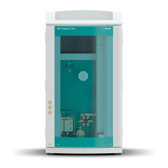
1 Introduction 1 Introduction Instrument description The 930 Compact IC Flex is a robust ion chromatograph. It is distinguished Its intelligence: All of the functions are monitored, optimized and docu- ■ mented in an FDA-compatible manner. Intelligent components, such as iColumns, save important data onto a chip. - Page 10 This lowers the background conductivity, improves detection sen- sitivity and minimizes the injection peak and system peak. Detector Metrohm offers a series of different detectors for various analysis tasks. A suitable detector type must be ordered as a separate device. Separation column The intelligent separation column separates different components accord- ing to their interactions with the column.
-
Page 11: Intended Use
■■■■■■■■■■■■■■■■■■■■■■ 1 Introduction Intended use The 930 Compact IC Flex SeS is used for the determination of anions, cati- ons or polar substances with sequential suppression using ion chromatog- raphy. Sequential suppression consists of: Chemical suppression with a Metrohm Suppressor Module (MSM) and ■... -
Page 12: Tubing And Capillary Connections
Damaged tubing ends lead to leakage. Appropriate tools can be used to loosen connections. Check the connections regularly for leakage. If the instrument is used mainly in unattended operation, then weekly inspections are manda- tory. ■■■■■■■■ 930 Compact IC Flex SeS (2.930.1400) -
Page 13: Flammable Solvents And Chemicals
Method Dialog text, parameter in the software File ▶ New Menu or menu item [Next] Button or key WARNING This symbol draws attention to a possible life-threat- ening hazard or risk of injury. ■■■■■■■■ 930 Compact IC Flex SeS (2.930.1400) - Page 14 WARNING This symbol draws attention to a possible biological hazard. CAUTION This symbol draws attention to possible damage to instruments or instrument parts. NOTE This symbol highlights additional information and tips. ■■■■■■■■ 930 Compact IC Flex SeS (2.930.1400)
-
Page 15: Overview Of The Instrument
Offers space for the eluent bottle and addi- For hanging the separation column (iCol- tional accessories. umn). With column recognition. Column chamber Metrohm Suppressor Module (MSM) Inline filter Injection valve Pulsation absorber Base tray With leak sensor. ■■■■■■■■ 930 Compact IC Flex SeS (2.930.1400) -
Page 16: Rear
Room for the detector and the adsorption cartridge for the MCS. Rear Figure 2 Rear Bottle holder Drainage tubing connection For connecting the drainage tubing, which guides escaped fluids away from the bottle holder. ■■■■■■■■ 930 Compact IC Flex SeS (2.930.1400) - Page 17 For connecting the instrument to the com- Plugged with a stopper. puter with the USB cable (6.2151.020). 21 Power socket Power socket for connecting the power cable and power switch for switching the instrument on and off. ■■■■■■■■ 930 Compact IC Flex SeS (2.930.1400)
-
Page 18: Feed-Throughs For Capillaries And Cables
The two Luer connections above are not actually openings; the capillaries are fastened to the Luer connection from within using PEEK pressure screws. You can use a syringe to inject or draw out liquid from the out- side. ■■■■■■■■ 930 Compact IC Flex SeS (2.930.1400) -
Page 19: Figure 4 Openings For Capillaries And Cables
The capillaries can be fed to the front of the instrument from both sides of the instrument and from the front of the instrument to the back of the instrument. ■■■■■■■■ 930 Compact IC Flex SeS (2.930.1400) -
Page 20: Figure 5 Ducts For Capillaries
■■■■■■■■■■■■■■■■■■■■■■ 2.3 Feed-throughs for capillaries and cables Figure 5 Ducts for capillaries ■■■■■■■■ 930 Compact IC Flex SeS (2.930.1400) -
Page 21: Installation
High-pressure pump, purge valve, inline filter, pulsation absorber, separation columns 6.2744.090 Pressure screw, long MCS, sample degasser, 10- port valve Pressure screws are tightened and loosened by hand. A tool is not nee- ded. ■■■■■■■■ 930 Compact IC Flex SeS (2.930.1400) - Page 22 (6.2739.000). ■ In order to achieve optimum analysis results, capillary connections in an IC system must be absolutely tight and free of dead volume. Dead volume ■■■■■■■■ 930 Compact IC Flex SeS (2.930.1400)
- Page 23 2 Heat the colored sleeve, e.g. with a hairdryer. The colored sleeve shrinks and adapts to the shape of the capillary. NOTE In order to arrange capillaries more clearly, they can be bundled with the spiral band (6.1815.010). ■■■■■■■■ 930 Compact IC Flex SeS (2.930.1400)
-
Page 24: Removing Transport Locking Screws
For the vacuum pump. Only present if the For the high-pressure pump. instrument has a degasser or a CO Suppres- sor (MCS). 1 Remove all of the transport locking screws with the hex key. ■■■■■■■■ 930 Compact IC Flex SeS (2.930.1400) -
Page 25: Connecting The Drainage Tubing And Leak Sensor
The drainage tubing is connected. ■ The leak sensor connection cable is inserted into the leak sensor con- ■ nection socket. The 930 Compact IC Flex is switched on. ■ The leak sensor is switched to active in the software. ■ 3.4.1... - Page 26 Attach the loose end to the right-side drainage tubing connection on the base tray. 6 Attach one end of the second piece of silicone tubing to the left-side drainage tubing connection on the base tray. ■■■■■■■■ 930 Compact IC Flex SeS (2.930.1400)
-
Page 27: Connecting The Leak Sensor
(see "Openings on the back panel", page 11) before the loose end can be connected to the eluent bottle. Accessories For this step, you need the following accessories: These parts are part of the accessory kit Vario/Flex ONE (6.5000.010). Eluent bottle (6.1608.070) ■ ■■■■■■■■ 930 Compact IC Flex SeS (2.930.1400) -
Page 28: Figure 7 Installing The Eluent Bottle Cap
Lastly, push the filter holder onto the loose end of the eluent aspi- ■ ration tubing and screw it onto the tubing nipple. The end of the tubing should extend approximately 1 cm. ■■■■■■■■ 930 Compact IC Flex SeS (2.930.1400) -
Page 29: Figure 8 Installing Tubing Weighting And Aspiration Filter
Installing tubing weighting and aspiration filter 5 Installing the eluent bottle cap on the eluent bottle Insert the eluent aspiration tubing into the eluent bottle ■ (6.1608.070). Tighten the bottle cap on the eluent bottle. ■ ■■■■■■■■ 930 Compact IC Flex SeS (2.930.1400) - Page 30 Fill the adsorber tube and close it again using the plastic cover. Insert the adsorber tube into the bottle cap's large opening. Fas- ■ ten it to the bottle cap using the SGJ clip (6.2023.020). ■■■■■■■■ 930 Compact IC Flex SeS (2.930.1400)
-
Page 31: Installing The High-Pressure Pump
"life history" (operating hours, service data, etc.) are saved. The high-pressure pump consists of: The pump head, which pumps the eluent through the system. ■ The purge valve used for bleeding the pump head. ■ ■■■■■■■■ 930 Compact IC Flex SeS (2.930.1400) -
Page 32: Installing An Inline Filter
The small filter pads with 2 µm pore size can be replaced quickly and easily. They remove particles from the solutions. An inline filter (6.2821.120) is installed between the purge valve and the pulsation absorber as protection against particles. ■■■■■■■■ 930 Compact IC Flex SeS (2.930.1400) -
Page 33: Installing The Pulsation Absorber
Figure 11 Pulsation absorber Connection capillary PEEK pressure screws, short Connection to inline filter. (6.2744.070) Pulsation absorber (6.2620.150) Holder for pulsation absorber Connection capillary Connection to injection valve. ■■■■■■■■ 930 Compact IC Flex SeS (2.930.1400) -
Page 34: Injection Valve
The quantity of sample solution injected is determined by: the volume of the sample loop or ■ by an 800 Dosino when the Metrohm intelligent Partial Loop Injection ■ Technique (MiPT) is used. The choice of sample loop depends on the application. The following... -
Page 35: Figure 12 Exchanging The Sample Loop
Fasten one end of the sample loop to Port 3 using a PEEK pressure ■ screw (6.2744.010). Use the second PEEK pressure screw (6.2744.010) to fasten the ■ other end of the sample loop to Port 6. ■■■■■■■■ 930 Compact IC Flex SeS (2.930.1400) -
Page 36: Metrohm Suppressor Module (Msm)
3.10 Metrohm Suppressor Module (MSM) 3.10 Metrohm Suppressor Module (MSM) The suppressor drive of the 930 Compact IC Flex can hold various rotors. The large rotors, such as the MSM‑HC Rotor A (6.2842.000) and the MSM-HC Rotor C (6.2842.200) can be inserted directly. - Page 37 ■■■■■■■■ 930 Compact IC Flex SeS (2.930.1400)
- Page 38 You need the adapter (6.2842.020) in order to insert a small rotor into the suppressor drive. 1 Inserting the rotor into the adapter CAUTION An incorrectly inserted rotor may be destroyed during start-up. ■■■■■■■■ 930 Compact IC Flex SeS (2.930.1400)
-
Page 39: Connecting The Metrohm Suppressor Module (Msm)
The three entries and exits of the suppressor units, numbered 1, 2 and 3 on the connecting piece, each have two permanently installed PTFE capil- laries. Figure 13 Metrohm Suppressor Module (MSM) – Connection capillaries Outlet capillary for the eluent. Inlet capillary for the eluent. ■■■■■■■■... - Page 40 1 Connect the capillary labeled in to the outlet of the separation col- umn using a short pressure screw (6.2744.070). 2 Use a long pressure screw (6.2744.090) to connect the capillary labeled out to the inlet of the MCS (see Chapter 3.11.2, page 37). ■■■■■■■■ 930 Compact IC Flex SeS (2.930.1400)
- Page 41 The regeneration solution is connected to the regenerant capillary. Connecting the regeneration solution to a Dosino For this step, you need the following accessories: Dosino (2.800.0010) ■ Accessory kit: Flex/Vario: SeS (6.5000.020) ■ IC equipment: Dosino Regeneration (6.5330.190) ■ ■■■■■■■■ 930 Compact IC Flex SeS (2.930.1400)
- Page 42 4 Connect the FEP tubing (6.1805.120) from the bottle with the regen- eration solution to Port 2 of the Dosino. 3.10.2.4 Connecting the rinsing solution Various possibilities exist for rinsing the Metrohm Suppressor Module: Rinsing solution via STREAM (recommended) ■ Use the eluent from the conductivity detector as rinsing solution.
- Page 43 3 short pressure screws (6.2744.070) ■ Inline filter (6.2821.120) ■ PTFE capillary (6.1803.030) ■ Adapter M6/UNF (6.2744.080) ■ FEP tubing M6 / 100 cm (6.1805.120) ■ Adapter Dosino Port 4, M6 inner (6.1808.280) ■ ■■■■■■■■ 930 Compact IC Flex SeS (2.930.1400)
-
Page 44: Metrohm Co Suppressor (Mcs)
The MCS essentially consists of a degassing cell containing a capillary made from a fluoropolymer membrane. The capillary is permeable to gases. The degassing cell is connected to the vacuum pump. In the ■■■■■■■■ 930 Compact IC Flex SeS (2.930.1400) -
Page 45: Connecting The Mcs
CO adsorption cartridge to filter out the CO from the air. 3.11.2 Connecting the MCS The MCS is connected between the Metrohm Suppressor Module (MSM) and the conductivity detector. Connecting the MCS Figure 14 Connecting the MCS Air aspiration capillary Pressure screw, short (6.2744.070) -
Page 46: Installing Adsorption Cartridges
CW for use as follows: 1 Remove the protective cap from the tip of the CO adsorption car- tridge CW. 2 Attach the dust filter to the tip of the CO adsorption cartridge CW. ■■■■■■■■ 930 Compact IC Flex SeS (2.930.1400) - Page 47 Installing the CO adsorption cartridge CW Accessories Adsorption cartridge holder (6.2057.080) ■ Prepared CO adsorption cartridge CW (6.2837.100) ■ CAUTION The following preparatory steps absolutely must be carried out for CO suppression to operate correctly. ■■■■■■■■ 930 Compact IC Flex SeS (2.930.1400)
- Page 48 Push two clips into the slots on the adsorption cartridge holder. ■ 2 Connecting the CO adsorption cartridge CW Attach the capillary connected to the Metrohm CO Suppressor's (MCS) Air in connection to the tip of the CO adsorption cartridge...
-
Page 49: Installing The Conductivity Detector
CW into the instrument's detector chamber. 3.12 Installing the conductivity detector The 930 Compact IC Flex provides enough space for one detector and additional accessories in the detector chamber. The detector is available as separate device and is supplied with a separate manual. -
Page 50: Installing The Amperometric Detector
(6.2744.090). 3.13 Installing the amperometric detector The 930 Compact IC Flex provides enough space for one detector and additional accessories in the detector chamber. The detector is available as separate device and is supplied with a separate manual. -
Page 51: Connecting The Instrument To The Power Grid
Unplug the power plug immediately if you suspect that moisture has ■ gotten inside the instrument. Only personnel who have been issued Metrohm qualification may ■ perform service and repair work on electrical and electronic parts. ■■■■■■■■... -
Page 52: Initial Start-Up
Also see: MagIC Net Tutorial and online help. 2 Preparing the instrument Ensure that the eluent aspiration tubing is immersed in the eluent ■ and that there is enough eluent in the eluent bottle. ■■■■■■■■ 930 Compact IC Flex SeS (2.930.1400) - Page 53 Check whether the detector outlet capillary is connected to the Metrohm Suppressor Module (MSM)'s inlet capillary for rinsing solu- tion (labeled rinsing solution).
-
Page 54: Connecting And Rinsing The Guard Column
Connecting and rinsing the guard column Guard columns protect separation columns and significantly increase their service life. The guard columns available from Metrohm are either actual guard columns or guard column cartridges used together with a cartridge holder. The process of installing a guard column cartridge into the corre- sponding holder is described in the guard column leaflet. - Page 55 Remove the coupling (6.2744.040) installed between the column inlet capillary and the column outlet capillary for the initial start-up. 2 Preparing the guard column Remove the stoppers or the stopper and the sealing cap from the ■ guard column. ■■■■■■■■ 930 Compact IC Flex SeS (2.930.1400)
-
Page 56: Connecting The Separation Column
NOTE Information regarding which separation column is suitable for your application can be found in the Metrohm Column Program, the product information for the separation column or it can be obtained through your representative. - Page 57 Applications area or request http://www.metrohm.com them from your responsible Metrohm representative free of charge. CAUTION New separation columns are filled with a solution and sealed with stop- pers on both sides. Before inserting the column, ensure that this solu- tion can be mixed with the eluent being used (follow the information provided by the manufacturer).
- Page 58 ■■■■■■■■■■■■■■■■■■■■■■ 3.18 Connecting the separation column Connecting the separation column 1 Removing the stoppers Remove the stoppers from the separation column. ■ ■■■■■■■■ 930 Compact IC Flex SeS (2.930.1400)
- Page 59 6 Inserting the separation column Insert the separation column with the chip into the column holder ■ until you hear it snap in place. The separation column is now detected by MagIC Net. ■■■■■■■■ 930 Compact IC Flex SeS (2.930.1400)
-
Page 60: Conditioning
Ensure that the eluent aspiration tubing is immersed in the eluent ■ and that there is enough eluent in the eluent bottle. 3 Starting equilibration Start the equilibration in MagIC Net: Workplace ▶ Run ▶ Equili- ■ bration ▶ Start HW. ■■■■■■■■ 930 Compact IC Flex SeS (2.930.1400) - Page 61 4 Conditioning the system Continue rinsing the system with eluent until the desired stability level for the baseline has been attained . The instrument is now ready for measuring samples. ■■■■■■■■ 930 Compact IC Flex SeS (2.930.1400)
-
Page 62: Operation
■■■■■■■■■■■■■■■■■■■■■■ 4 Operation The 930 Compact IC Flex SeS is operated solely using the MagIC Net soft- ware. You can find information on operating the software in the tutorial for MagIC Net or in the online help. ■■■■■■■■ 930 Compact IC Flex SeS (2.930.1400) -
Page 63: Operation And Maintenance
Maintenance by Metrohm Service Maintenance of the instrument is best carried out as part of an annual service performed by specialist personnel from Metrohm. A shorter main- tenance interval is recommended if you frequently work with caustic and corrosive chemicals. Metrohm Service offers every form of technical advice for maintenance and service of all Metrohm instruments. -
Page 64: Shutting Down And Recommissioning
3 Rinse the IC system for 15 minutes with methanol/ultrapure water mixture (1:4). 4 Optional: Only if the IC system is equipped with a suppressor. In the software, switch the Metrohm Suppressor Module (MSM) twice during the rinsing process at five-minute intervals in each case (STEP command). -
Page 65: Capillary Connections
To protect the IC system from foreign particles, we recommend aspirat- ■ ing the eluent via an aspiration filter (see Chapter 3.5, page 19) (6.2821.090). This aspiration filter must be replaced as soon as it turns yellow but at least every 3 months. ■■■■■■■■ 930 Compact IC Flex SeS (2.930.1400) -
Page 66: Manufacturing Eluent
NOTE To change the eluent, remove the guard column and the separation col- umn. Connect the capillaries using a coupling (6.2744.040) and two pressure screws (6.2744.070). ■■■■■■■■ 930 Compact IC Flex SeS (2.930.1400) -
Page 67: Notes On Operating The High-Pressure Pump
Servicing the high-pressure pump NOTE You can find a video sequence for this task in the Multimedia Guide IC Maintenance or on the Internet at http://ic-help.metrohm.com/. ■■■■■■■■ 930 Compact IC Flex SeS (2.930.1400) -
Page 68: Figure 15 High-Pressure Pump - Parts
Maintenance tasks can also be carried out if the following problems occur: Unstable baseline (pulsations, flow fluctuations) ■ CAUTION Maintenance work on the high-pressure pump may not be carried out unless the instrument is switched off. ■■■■■■■■ 930 Compact IC Flex SeS (2.930.1400) - Page 69 Internet at http://ic-help.metrohm.com/. Servicing the outlet valve and inlet valve Accessories For this step, you need the following accessories: You can find these parts in the accessory kit: Vario/Flex Basic (6.5000.000). Adjustable wrench (6.2621.000) ■ ■■■■■■■■ 930 Compact IC Flex SeS (2.930.1400)
- Page 70 RBS™ solution or acetone. The rinsing solution may only come out at the valve outlet. The outlet valve must be replaced if it is still clogged after cleaning. ■■■■■■■■ 930 Compact IC Flex SeS (2.930.1400)
- Page 71 ¼ turn using the adjustable wrench (3). Tighten the connection capillary to the auxiliary piston back onto ■ the outlet valve holder. ■■■■■■■■ 930 Compact IC Flex SeS (2.930.1400)
- Page 72 RBS™ solution or acetone. The rinsing solution may only come out at the valve outlet. The inlet valve must be replaced if it is still clogged after cleaning. ■■■■■■■■ 930 Compact IC Flex SeS (2.930.1400)
- Page 73 You can find these parts in the accessory kit: Vario/Flex Basic (6.5000.000). 4 mm hex key (6.2621.030) ■ Removing the pump head Prerequisites: Is the high-pressure pump switched off? ■ Has the pressure been released? ■ Is the instrument switched off? ■ ■■■■■■■■ 930 Compact IC Flex SeS (2.930.1400)
- Page 74 Servicing the piston Carry out the following work on both pistons in turn. Servicing a piston consists of the following tasks: Replace the piston seal. Clean or replace the zirconium oxide piston. Reinstall the piston. ■■■■■■■■ 930 Compact IC Flex SeS (2.930.1400)
-
Page 75: Figure 16 High-Pressure Pump - Cross-Section
(6.5000.000). Adjustable wrench (6.2621.000) ■ Tool for piston seals (6.2617.010) consisting of a tip (17-1) for remov- ■ ing the old piston seal and a sleeve (17-2) for inserting the new piston seal. ■■■■■■■■ 930 Compact IC Flex SeS (2.930.1400) -
Page 76: Figure 17 Tool For Piston Seal (6.2617.010)
Loosen the piston cartridge (18-1) using the adjustable wrench and then unscrew it from the pump head by hand. Set it aside. 2 Removing the backup ring Shake the backup ring (18-2) out of the piston opening. Set it aside. ■■■■■■■■ 930 Compact IC Flex SeS (2.930.1400) -
Page 77: Figure 19 Inserting The Piston Seal Into The Tool
Press the seal into the pump head recess using the wide end of the tip (17-1) of the tool. Cleaning or replacing the zirconium oxide piston Prerequisites: ■■■■■■■■ 930 Compact IC Flex SeS (2.930.1400) -
Page 78: Figure 20 Parts Of The Piston Cartridge
Place the backup ring you put aside with the remaining parts. ■ Figure 20 Parts of the piston cartridge Piston cartridge screw Retaining washer Zirconium oxide piston (6.2824.070) Spring retainer Spring (6.2824.060) Inner plastic sleeve Protects from metallic abrasion. Piston cartridge Backup ring ■■■■■■■■ 930 Compact IC Flex SeS (2.930.1400) - Page 79 Clean the second piston cartridge in the same way. Mounting the pump head Accessories For this step, you need the following accessories: You can find these parts in the accessory kit: Vario/Flex Basic (6.5000.000). ■■■■■■■■ 930 Compact IC Flex SeS (2.930.1400)
- Page 80 The bore hole with the greatest depth must therefore be aligned with the longest bolt. Push the pump head onto the four fastening bolts (1). ■ Tighten the four fastening screws using the hex key (6.2621.030) ■ alternating crosswise. ■■■■■■■■ 930 Compact IC Flex SeS (2.930.1400)
-
Page 81: Servicing The Inline Filter
Servicing the inline filter NOTE You can find a video sequence for this task in the Multimedia Guide IC Maintenance or on the Internet at http://ic-help.metrohm.com/. Maintenance interval The filter must be replaced at least every 3 months; it may need to be replaced more frequently, depending on the application. -
Page 82: Figure 21 Inline Filter - Removing The Filter
3 Unscrewing the filter screw Use two adjustable wrenches (6.2621.000) to loosen the filter screw (21-2) from the filter housing (21-1) and unscrew it by hand. 4 Removing the filter Remove the old filter (21-3) using tweezers. ■■■■■■■■ 930 Compact IC Flex SeS (2.930.1400) - Page 83 4 Rinsing the inline filter Dismantle the guard column (if present) and the separation col- ■ umn and replace with a coupling (6.2744.040). Rinse the instrument with eluent. ■ Reinsert the columns after 10 minutes. ■ ■■■■■■■■ 930 Compact IC Flex SeS (2.930.1400)
-
Page 84: Servicing The Pulsation Absorber
If the Metrohm Suppressor Module (MSM) is in a dry state, it must be rinsed for at least five minutes before it may be switched over. -
Page 85: Taking Care Of The Suppressor Housing
■■■■■■■■■■■■■■■■■■■■■■ 5 Operation and maintenance CAUTION The Metrohm Suppressor Module (MSM) must be regenerated (see Chapter 5.10.3.2, page 78), cleaned (see Chapter 5.10.3.4, page 80) or replaced (see Chapter 5.10.3.5, page 83) if the capacity of the Met- rohm Suppressor Module (MSM) is reduced or if the back pressure is high. - Page 86 Pump tubing made of PVC must not be used for solutions containing organic solvents. We recommend using the high-pressure pump for regeneration. Regenerating the anion suppressor rotor 1 Disconnecting the Metrohm Suppressor Module (MSM) from the IC system Disconnect the capillaries of the MSM labeled regenerant and ■...
- Page 87 As soon as all three suppressor units have been rinsed, disconnect ■ the capillary labeled rinsing solution from the coupling. 4 Connecting the Metrohm Suppressor Module (MSM) to the IC system Reconnect the capillaries of the MSM labeled regenerant and ■...
- Page 88 Equilibrate the system as usual (see chapter "Conditioning" in the manual for the ion chromatograph). 5.10.3.4 Cleaning the Metrohm Suppressor Module (MSM) In the following cases, it may be necessary to clean the Metrohm Suppres- sor Module (MSM): Increased back pressure at the MSM's connection tubing. ■ ■■■■■■■■...
- Page 89 Check whether water comes out at the connecting piece. ■ If one of the capillaries remains blocked, the connecting piece (see "Replacing parts of the Metrohm Suppressor Module (MSM)", page 83) must be replaced (order number 6.2835.010). 4 Cleaning the rotor Clean the sealing surface of the rotor (22-3) with ethanol using a ■...
- Page 90 Reattach the union nut (22-1) and tighten by hand (do not use a ■ tool). 8 Connecting and conditioning the Metrohm Suppressor Mod- ule (MSM) Reconnect the MSM to the IC system. ■...
- Page 91 5 Operation and maintenance 5.10.3.5 Replacing parts of the Metrohm Suppressor Module (MSM) Parts of the Metrohm Suppressor Module (MSM) may need to be replaced in the following cases: Irremediable loss of suppressor capacity (reduced phosphate sensitivity ■ and/or significant rise in the baseline).
- Page 92 1 is on top and the three pins of the connecting piece fit into the corresponding recesses on the housing. Reattach the union nut (22-1) and tighten by hand (do not use a ■ tool). ■■■■■■■■ 930 Compact IC Flex SeS (2.930.1400)
-
Page 93: Servicing The Metrohm Co
CW 1 Remove the depleted CO adsorption cartridge CW from the adsorp- tion cartridge holder. 2 Remove the Air in capillary of the Metrohm CO Suppressor (MCS). 3 Professionally dispose of the depleted CO adsorption cartridge CW. Installing the new CO... -
Page 94: Servicing The Detector
The time upon stopping the watch is the "transfer time". 4 Tightening the sample loop again Tighten the sample loop again. ■■■■■■■■ 930 Compact IC Flex SeS (2.930.1400) -
Page 95: Separation Column
You can find detailed information on the separation columns available from Metrohm in the leaflet provided along with your separation column, in the Metrohm IC Column Program (available from your Metrohm representative) or on the Internet at http://www.metrohm.com... -
Page 96: Protecting The Separation Column
The separation column can be regenerated according to the column man- ufacturer's specifications if the separation characteristics of the column have deteriorated. You can find information on regenerating separation columns available from Metrohm on the leaflet provided with every col- umn. NOTE Regeneration is intended as a last resort. -
Page 97: Quality Management And Qualification With Metrohm
Metrohm offers you comprehensive support in implementing quality man- agement measures for instruments and software. Qualification Please contact your local Metrohm representative for support in qualifica- tion of instruments and software. The Installation Qualification (IQ) and Operational Qualification (OQ) are offered by Metrohm represen- tatives as a service. -
Page 98: Troubleshooting
Check the eluent bottle cap (see Chapter ■ eluent is evaporating. 3.5, page 19). Constantly stir the eluent. ■ The pressure in the The inline filter Replace the filter (6.2821.130) . system markedly (6.2821.120) is blocked. increases. ■■■■■■■■ 930 Compact IC Flex SeS (2.930.1400) - Page 99 Replace the separation column (see "Con- ■ necting the separation column", page 50). Note: Samples should always be microfiltered . Injection valve – blocked. Have the valve cleaned (by a Metrohm service engineer). The retention times Eluent - Incorrect concen- Create eluent with correct concentration.
- Page 100 MSM – Reduced capacity. Regenerate the MSM (see Chapter 5.10.3.2, page 78). SPM – Reduced capacity. Regenerate the SPM (see Chapter 5.10.3.2, page 78). ■■■■■■■■ 930 Compact IC Flex SeS (2.930.1400)
- Page 101 Increase the rinsing time (see Chapter 5.13, ume is too small. page 86). Injection valve – Defective. Request Metrohm Service. MCS – The vacuum is too Check the connectors. If they are OK: ■ low. Contact Metrohm Service. ■ ■■■■■■■■ 930 Compact IC Flex SeS (2.930.1400)
-
Page 102: Technical Specifications
Ambient conditions Operation Ambient tem- +5 - +45 °C perature Humidity 20 - 80% relative humidity Storage Ambient tem- –20 - +70 °C perature Transport Ambient tem- –40 - +70 °C perature ■■■■■■■■ 930 Compact IC Flex SeS (2.930.1400) -
Page 103: Housing
Reproducibility of the eluent flow Pressure range Pump 0 - 50.0 MPa (0 - 500 bar) Pump head 0 - 35.0 MPa (0 - 350 bar) (applies for the standard PEEK pump head) ■■■■■■■■ 930 Compact IC Flex SeS (2.930.1400) -
Page 104: Injection Valve
100 ms 7.10 Metrohm CO Suppressor (MCS) Material Fluoropolymer Resistance to sol- No restriction (except PFC) vents Vacuum Microprocessor-controlled/stabilized Working range Time to estab- < 30 s lish after start- Capillary volume 400 µL ■■■■■■■■ 930 Compact IC Flex SeS (2.930.1400) -
Page 105: Detector
1 15-pin high-density D-sub (female) (labeled Detector) Column recogni- for an intelligent column tion Leak sensor 1 jack plug (labeled Leak Sensor) Further connec- tions Auxiliary 1 15-pin DSUB (female) Service 1 15-pin DSUB (female) ■■■■■■■■ 930 Compact IC Flex SeS (2.930.1400) -
Page 106: Accessories
The PDF file with the accessories data will be created. NOTE When you receive your new instrument, we recommend downloading the accessories list from the Internet, printing it out and keeping it together with the manual for reference purposes. ■■■■■■■■ 930 Compact IC Flex SeS (2.930.1400) -
Page 107: Index
Humidity ........94 Heavy metals ...... 78 Installation ......36 Organic ......78 Technical specifications ..96 Crystallization Use ........36 IC column High-pressure pump ... 59 MSB ......... 97 see "Separation column" ..48 ■■■■■■■■ 930 Compact IC Flex SeS (2.930.1400) - Page 108 Regeneration ......55 See also "Injection valve" ..26 Installation ......28 Anion suppressor ....78 Maintenance ...... 76 Cation suppressor ....80 Operation ......76 Rinse Replacing parts ....83 Guard column ....48 ■■■■■■■■ 930 Compact IC Flex SeS (2.930.1400)
Need help?
Do you have a question about the 930 Compact IC Flex and is the answer not in the manual?
Questions and answers