Metrohm 940 Professional IC Vario Manual
Hide thumbs
Also See for 940 Professional IC Vario:
- Manual (90 pages) ,
- Manual - short instructions (52 pages) ,
- Manual (95 pages)

Related Manuals for Metrohm 940 Professional IC Vario


Summary of Contents for Metrohm 940 Professional IC Vario
- Page 1 940 Professional IC Vario 940 Professional IC Vario ONE/SeS/PP/Prep 3 Manual 8.940.8021EN / 2017-07-31...
- Page 3 Metrohm AG CH-9100 Herisau Switzerland Phone +41 71 353 85 85 Fax +41 71 353 89 01 info@metrohm.com www.metrohm.com 940 Professional IC Vario 940 Professional IC Vario ONE/SeS/PP/Prep 3 2.940.1530 Manual 8.940.8021EN / 2017-07-31...
- Page 4 Technical Communication Metrohm AG CH-9100 Herisau techcom@metrohm.com This documentation is protected by copyright. All rights reserved. This documentation has been prepared with great care. However, errors can never be entirely ruled out. Please send comments regarding possible errors to the address above.
-
Page 5: Table Of Contents
3.10 Installing an inline filter ............. 28 3.11 Installing the pulsation absorber ........28 3.12 Injection valve ..............29 3.13 Metrohm Suppressor Module (MSM) ....... 31 3.13.1 Inserting the rotors ..............32 ■■■■■■■■ 940 Professional IC Vario ONE/SeS/PP/Prep 3 (2.940.1530) - Page 6 ■■■■■■■■■■■■■■■■■■■■■■ Table of contents 3.13.2 Connecting the Metrohm Suppressor Module (MSM) ..... 35 3.14 Peristaltic pump ..............40 3.14.1 Installing the peristaltic pump ..........40 3.14.2 Mode of operation for the peristaltic pump ......45 3.15 Metrohm CO Suppressor (MCS) ........46 3.15.1...
- Page 7 Notes for operating the Metrohm Suppressor Module (MSM) ................... 93 5.12.2 Taking care of the suppressor housing ........94 5.12.3 Servicing the Metrohm Suppressor Module (MSM) ....94 5.13 Peristaltic pump ..............103 5.13.1 Notes on operating the peristaltic pump ......103 5.13.2 Servicing the peristaltic pump ..........
- Page 8 ■■■■■■■■■■■■■■■■■■■■■■ Table of contents 7.14 Detector ................121 7.15 Sample degasser ............... 121 7.16 Sample preparation module (SPM) ......... 121 7.17 Power connection ............. 122 7.18 Interfaces ................122 8 Accessories Index ■■■■■■■■ 940 Professional IC Vario ONE/SeS/PP/Prep 3 (2.940.1530)
- Page 9 Figure 11 Pulsation absorber ................29 Figure 12 Exchanging the sample loop ............30 Figure 13 Metrohm Suppressor Module (MSM) – Connection capillaries ..35 Figure 14 Peristaltic pump ................46 Figure 15 Connecting the MCS ............... 47 Figure 16 SPM –...
-
Page 11: Introduction
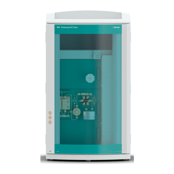
■■■■■■■■■■■■■■■■■■■■■■ 1 Introduction 1 Introduction Instrument description The 940 Professional IC Vario is a professional ion chromatograph. It is dis- tinguished by: Its intelligence: All of the functions are monitored, optimized and docu- ■ mented in an FDA-compatible manner. Intelligent components, such as iColumns, save important data onto a chip. - Page 12 The rotors are not included in the instru- ment's scope of delivery. The rotor required for the application and any adapter that is required must be ordered separately. ■■■■■■■■ 940 Professional IC Vario ONE/SeS/PP/Prep 3 (2.940.1530)
-
Page 13: Intended Use
(start-up, operating hours, injections etc) are stored. Intended use The 940 Professional IC Vario ONE/SeS/PP/Prep 3 is used for the determi- nation of anions, cations or polar substances with sequential suppression using ion chromatography. -
Page 14: Safety Instructions
1.3 Safety instructions This instrument is suitable for processing chemicals and flammable sam- ples. Usage of the 940 Professional IC Vario therefore requires the user to have basic knowledge and experience in handling toxic and caustic sub- stances. Knowledge regarding the application of fire prevention measures prescribed for laboratories is also mandatory. -
Page 15: Tubing And Capillary Connections
Damaged tubing ends lead to leakage. Appropriate tools can be used to loosen connections. Check the connections regularly for leakage. If the instrument is used mainly in unattended operation, then weekly inspections are manda- tory. ■■■■■■■■ 940 Professional IC Vario ONE/SeS/PP/Prep 3 (2.940.1530) -
Page 16: Flammable Solvents And Chemicals
Dialog text, parameter in the software File ▶ New Menu or menu item [Next] Button or key WARNING This symbol draws attention to a possible life-threat- ening hazard or risk of injury. ■■■■■■■■ 940 Professional IC Vario ONE/SeS/PP/Prep 3 (2.940.1530) - Page 17 WARNING This symbol draws attention to a possible biological hazard. CAUTION This symbol draws attention to possible damage to instruments or instrument parts. NOTE This symbol highlights additional information and tips. ■■■■■■■■ 940 Professional IC Vario ONE/SeS/PP/Prep 3 (2.940.1530)
-
Page 18: Overview Of The Instrument
Offers space for the eluent bottle(s) and Offers space for two embedded detectors additional accessories. and additional accessories. Column holder Metrohm CO Suppressor (MCS) For a third separation column outside the column thermostat. ■■■■■■■■ 940 Professional IC Vario ONE/SeS/PP/Prep 3 (2.940.1530) - Page 19 For the sample preparation. With leak sensor. 13 Peristaltic pump 14 Purge valve For transporting solutions for sample prepa- For deaerating the high-pressure pump. ration. 15 High-pressure pump 16 Eluent degasser 17 Peristaltic pump ■■■■■■■■ 940 Professional IC Vario ONE/SeS/PP/Prep 3 (2.940.1530)
-
Page 20: Rear
Up to two vac- tor chamber. uum pumps can be installed in an instru- ment. Only two transport locking screws are used if just one vacuum pump is installed. ■■■■■■■■ 940 Professional IC Vario ONE/SeS/PP/Prep 3 (2.940.1530) -
Page 21: Feed-Throughs For Capillaries And Cables
Openings on the door (see Figure 3, page 12) ■ Openings on the back panel ■ Ducts between the instrument and the base tray as well as between ■ the instrument and the bottle holder (see Figure 5, page 14) ■■■■■■■■ 940 Professional IC Vario ONE/SeS/PP/Prep 3 (2.940.1530) -
Page 22: Figure 3 Feed-Throughs On The Door
The two Luer connections above are not actually openings; the capillaries are fastened to the Luer connection from within using PEEK pressure screws. You can use a syringe to inject or draw out liquid from the out- side. ■■■■■■■■ 940 Professional IC Vario ONE/SeS/PP/Prep 3 (2.940.1530) -
Page 23: Figure 4 Openings For Capillaries And Cables
The capillaries can be fed to the front of the instrument from both sides of the instrument and from the front of the instrument to the back of the instrument. ■■■■■■■■ 940 Professional IC Vario ONE/SeS/PP/Prep 3 (2.940.1530) -
Page 24: Figure 5 Ducts For Capillaries
■■■■■■■■■■■■■■■■■■■■■■ 2.3 Feed-throughs for capillaries and cables Figure 5 Ducts for capillaries ■■■■■■■■ 940 Professional IC Vario ONE/SeS/PP/Prep 3 (2.940.1530) -
Page 25: Installation
High-pressure pump, purge valve, inline filter, pulsation absorber, separation columns 6.2744.090 Pressure screw, long MCS, sample degasser, 10- port valve Pressure screws are tightened and loosened by hand. A tool is not nee- ded. ■■■■■■■■ 940 Professional IC Vario ONE/SeS/PP/Prep 3 (2.940.1530) - Page 26 (6.2739.000). ■ In order to achieve optimum analysis results, capillary connections in an IC system must be absolutely tight and free of dead volume. Dead volume ■■■■■■■■ 940 Professional IC Vario ONE/SeS/PP/Prep 3 (2.940.1530)
- Page 27 2 Heat the colored sleeve, e.g. with a hairdryer. The colored sleeve shrinks and adapts to the shape of the capillary. NOTE In order to arrange capillaries more clearly, they can be bundled with the spiral band (6.1815.010). ■■■■■■■■ 940 Professional IC Vario ONE/SeS/PP/Prep 3 (2.940.1530)
-
Page 28: Removing The Handle
The handle can be removed once the instrument is in place in the lab. Accessories You do not need any accessories for the following work steps. Removing the handle 1 Removing the handle Unscrew the four knurled screws. ■ Remove the handle. ■ ■■■■■■■■ 940 Professional IC Vario ONE/SeS/PP/Prep 3 (2.940.1530) -
Page 29: Removing Transport Locking Screws
For the vacuum pump. For the high-pressure pump. Transport locking screws For an additional high-pressure pump in the bottom drawer. 1 Remove all of the transport locking screws with the hex key. ■■■■■■■■ 940 Professional IC Vario ONE/SeS/PP/Prep 3 (2.940.1530) -
Page 30: Connecting The Drainage Tubing And Leak Sensor
The drainage tubing is connected. ■ The leak sensor connection cable is inserted into the leak sensor con- ■ nection socket. The 940 Professional IC Vario is switched on. ■ The leak sensor is switched to active in the software. ■ 3.5.1... - Page 31 Attach the loose end to the right-side drainage tubing connection on the base tray. 6 Attach one end of the second piece of silicone tubing to the left-side drainage tubing connection on the base tray. ■■■■■■■■ 940 Professional IC Vario ONE/SeS/PP/Prep 3 (2.940.1530)
-
Page 32: Connecting The Leak Sensor
The capillaries are fed through small openings on the inner front edge, so that they do not get pinched when the door is closed. The column thermostat is completely connected. No installation work is required. ■■■■■■■■ 940 Professional IC Vario ONE/SeS/PP/Prep 3 (2.940.1530) -
Page 33: Connecting The Eluent Bottle
Push the loose end of the eluent aspiration tubing through the ■ M8 opening of the bottle cap and screw it on for the time being. Figure 7 Installing the eluent bottle cap ■■■■■■■■ 940 Professional IC Vario ONE/SeS/PP/Prep 3 (2.940.1530) - Page 34 Place the loose end of the eluent aspiration tubing into the aspira- ■ tion filter. The end of the tubing should reach approximately to the center of the aspiration filter. Tighten the aspiration filter to the filter holder. ■ ■■■■■■■■ 940 Professional IC Vario ONE/SeS/PP/Prep 3 (2.940.1530)
-
Page 35: Figure 8 Installing Tubing Weighting And Aspiration Filter
Then fix it in place using the M8 tubing nipple. Seal the M6 opening on the bottle cap with the M6 threaded ■ stopper from the accessory set. ■■■■■■■■ 940 Professional IC Vario ONE/SeS/PP/Prep 3 (2.940.1530) - Page 36 Fill the adsorber tube and close it again using the plastic cover. Insert the adsorber tube into the bottle cap's large opening. Fas- ■ ten it to the bottle cap using the SGJ clip (6.2023.020). ■■■■■■■■ 940 Professional IC Vario ONE/SeS/PP/Prep 3 (2.940.1530)
-
Page 37: Connecting The Eluent Degasser
The purge valve used for bleeding the pump head. ■ Figure 9 High-pressure pump with purge valve Pump head Purge valve The high-pressure pump is completely connected. No installation work is required. ■■■■■■■■ 940 Professional IC Vario ONE/SeS/PP/Prep 3 (2.940.1530) -
Page 38: Installing An Inline Filter
The pulsation absorber is installed between the high-pressure pump and the injection valve. It protects the separation column from damage caused by pressure fluctuations, e.g. when the injection valve is switched, and reduces interfering pulsations during highly sensitive measurements. ■■■■■■■■ 940 Professional IC Vario ONE/SeS/PP/Prep 3 (2.940.1530) -
Page 39: Injection Valve
The quantity of sample solution injected is determined by: the volume of the sample loop or ■ by an 800 Dosino when the Metrohm intelligent Partial Loop Injection ■ Technique (MiPT), the Metrohm intelligent Pick-up Injection Technique (MiPuT) or the Metrohm Inline Preconcentration (MiPCT, MiPCT-ME) is used. -
Page 40: Figure 12 Exchanging The Sample Loop
Only use PEEK pressure screws (6.2744.010) to connect capillaries and the sample loop to the injection valve. Figure 12 Exchanging the sample loop Pressure screw Sample loop Fastened to Port 6. Pressure screw Fastened to Port 3. ■■■■■■■■ 940 Professional IC Vario ONE/SeS/PP/Prep 3 (2.940.1530) -
Page 41: Metrohm Suppressor Module (Msm)
Port 6. 3.13 Metrohm Suppressor Module (MSM) The suppressor drive of the 940 Professional IC Vario can hold various rotors. The large rotors, such as the SPM Rotor A (6.2835.000), the MSM‑HC Rotor A (6.2842.000) and the MSM-HC Rotor C (6.2842.200) can be inserted directly. -
Page 42: Inserting The Rotors
Connecting piece (6.2835.010) ■ Large rotors can be inserted directly into the rotor housing. CAUTION The rotor may be destroyed during start-up if not inserted correctly. Therefore, follow the following instructions exactly. ■■■■■■■■ 940 Professional IC Vario ONE/SeS/PP/Prep 3 (2.940.1530) - Page 43 If the rotor cannot be turned or removed, it can be moved into the correct position from below by means of a pointed object (e.g. a screwdriver). ■■■■■■■■ 940 Professional IC Vario ONE/SeS/PP/Prep 3 (2.940.1530)
- Page 44 2 Inserting the adapter Insert the adapter into the suppressor drive just like a large rotor (see "Inserting large rotors", page 33). ■■■■■■■■ 940 Professional IC Vario ONE/SeS/PP/Prep 3 (2.940.1530)
-
Page 45: Connecting The Metrohm Suppressor Module (Msm)
Inlet capillary for the regeneration solution. Outlet capillary for the regeneration solu- tion; to the waste container. waste rins. rinsing solution Outlet capillary for the rinsing solution; to Inlet capillary for the rinsing solution. the waste container. ■■■■■■■■ 940 Professional IC Vario ONE/SeS/PP/Prep 3 (2.940.1530) - Page 46 Glass bottle / 1000 mL / GL 45 (6.1608.020) ■ Bottle cap / GL 45 - 3 × UNF 10/32 (6.1602.150) ■ PTFE capillary, 0.5 mm inner diameter / 3 m (6.1803.030) ■ ■■■■■■■■ 940 Professional IC Vario ONE/SeS/PP/Prep 3 (2.940.1530)
- Page 47 For this step, you need the following accessories: Accessory kit: Flex/Vario: SeS (6.5000.020) ■ Pump tubing (6.1826.420) ■ Tubing olive with filter and locking nut (6.2744.180) ■ Tubing olive (6.2744.034) ■ Tubing cartridge of the peristaltic pump ■ ■■■■■■■■ 940 Professional IC Vario ONE/SeS/PP/Prep 3 (2.940.1530)
- Page 48 3 Connect the PTFE capillary from the regeneration solution bottle to the inlet of the pump tubing. 3.13.2.4 Connecting the rinsing solution Various possibilities exist for rinsing the Metrohm Suppressor Module: Rinsing solution via STREAM (recommended) ■ Use the eluent from the conductivity detector as rinsing solution.
- Page 49 2 Connect the capillary labeled rinsing solution to the outlet of the pump tubing using a pressure screw (6.2744.070). 3 Connect the PTFE capillary from the rinsing solution bottle to the inlet of the pump tubing. ■■■■■■■■ 940 Professional IC Vario ONE/SeS/PP/Prep 3 (2.940.1530)
-
Page 50: Peristaltic Pump
1 Select pump tubing suitable for the application (see Table 2, page 40). 2 Select an adapter suitable for the pump tubing. The adapters are included with the pump tubing connection with locking nut and filter (6.2744.180). ■■■■■■■■ 940 Professional IC Vario ONE/SeS/PP/Prep 3 (2.940.1530) - Page 51 Coupling olive/UNF 10/32 (6.2744.034) ■ Pump tubing connection with locking nut and filter (6.2744.180): ■ Includes a locknut, 3 adapters and a tubing olive with filter holder. 2 × pressure screw, short (6.2744.070) ■ ■■■■■■■■ 940 Professional IC Vario ONE/SeS/PP/Prep 3 (2.940.1530)
- Page 52 – Tighten it using the union nut. 2 Removing the tubing cartridge Press in the tubing cartridge's snap-action lever. ■ Tilt the tubing cartridge upwards. ■ Unhook the tubing cartridge from the mounting bolt. ■ ■■■■■■■■ 940 Professional IC Vario ONE/SeS/PP/Prep 3 (2.940.1530)
- Page 53 Connecting capillaries for rinsing solution (as an alternative to STREAM) Accessories For this step, you need the following accessories: Aspiration capillary (6.1803.030) ■ 2 × pressure screw, short (6.2744.070) ■ ■■■■■■■■ 940 Professional IC Vario ONE/SeS/PP/Prep 3 (2.940.1530)
- Page 54 The rotational speed of the drive ■ The contact pressure of the tubing cartridge ■ NOTE Pieces of pump tubing are consumables. The service life of the pump tubing depends on the contact pressure, among other factors. ■■■■■■■■ 940 Professional IC Vario ONE/SeS/PP/Prep 3 (2.940.1530)
-
Page 55: Mode Of Operation For The Peristaltic Pump
The pump tubing is clamped between the rollers (14-5) and the tubing cartridge (14-2). During operation, the peristaltic pump drive rotates the roller hub (14-6), so that the rollers (14-5) advance the liquid in the pump tubing. ■■■■■■■■ 940 Professional IC Vario ONE/SeS/PP/Prep 3 (2.940.1530) -
Page 56: Metrohm Co Suppressor (Mcs)
The degassing cell is connected to the vacuum pump. In the degassing cell, the eluent is directed through the capillary made of a fluo- ropolymer membrane. At the same time, the vacuum pump generates a ■■■■■■■■ 940 Professional IC Vario ONE/SeS/PP/Prep 3 (2.940.1530) -
Page 57: Connecting The Mcs
CO adsorption cartridge to filter out the CO from the air. 3.15.2 Connecting the MCS The MCS is connected between the Metrohm Suppressor Module (MSM) and the conductivity detector. Connecting the MCS Figure 15 Connecting the MCS Air aspiration capillary Pressure screw, short (6.2744.070) -
Page 58: Installing Adsorption Cartridges
CW for use as follows: 1 Remove the protective cap from the tip of the CO adsorption car- tridge CW. 2 Attach the dust filter to the tip of the CO adsorption cartridge CW. ■■■■■■■■ 940 Professional IC Vario ONE/SeS/PP/Prep 3 (2.940.1530) - Page 59 CW Accessories Adsorption cartridge holder (6.2057.080) ■ Prepared CO adsorption cartridge CW (6.2837.100) ■ CAUTION The following preparatory steps absolutely must be carried out for CO suppression to operate correctly. ■■■■■■■■ 940 Professional IC Vario ONE/SeS/PP/Prep 3 (2.940.1530)
- Page 60 Push two clips into the slots on the adsorption cartridge holder. ■ 2 Connecting the CO adsorption cartridge CW Attach the capillary connected to the Metrohm CO Suppressor's (MCS) Air in connection to the tip of the CO adsorption cartridge...
-
Page 61: Installing The Conductivity Detector
CW into the instrument's detector chamber. 3.16 Installing the conductivity detector The 940 Professional IC Vario provides enough space for two detectors and additional accessories in the detector chamber. The detectors are available as separate devices and are supplied with separate manuals. -
Page 62: Installing The Amperometric Detector
(6.2744.090). 3.17 Installing the amperometric detector The 940 Professional IC Vario provides enough space for two detectors and additional accessories in the detector chamber. The detectors are available as separate devices and are supplied with separate manuals. - Page 63 3 Connecting the inlet capillary Push a long pressure screw over one end of the PTFE capillary ■ (6.1803.040) and tighten the pressure screw to the inlet of the sample degasser (labeled In). ■■■■■■■■ 940 Professional IC Vario ONE/SeS/PP/Prep 3 (2.940.1530)
-
Page 64: Sample Preparation Module (Spm)
For cation exchange before the sample is injected. ■ For neutralizing a sample. ■ You can find more information on these preparation techniques in the "Metrohm Inline Sample Preparation (MISP)" brochure (available on the Internet at documents.metrohm.com by searching for "MISP"). 3.19.2... -
Page 65: Figure 16 Spm - Connection Capillaries
Pump tubing connections with locking nut and filter (6.2744.180) have to be installed on the outlet of the peristaltic pump's pump tubing in order to protect the SPM from foreign particles and bacterial growth. ■■■■■■■■ 940 Professional IC Vario ONE/SeS/PP/Prep 3 (2.940.1530) - Page 66 ■ injection valve. 3 Connecting the rinsing solution inlet capillary Fasten the capillary labeled rinsing solution to the pump tubing ■ connection carrying the rinsing solution using a short pressure screw (6.2744.070). ■■■■■■■■ 940 Professional IC Vario ONE/SeS/PP/Prep 3 (2.940.1530)
-
Page 67: Connecting The Instrument To A Computer
Connecting the instrument to a computer NOTE If the instrument is connected to the computer, then it must be switched off. Accessories For this step, you need the following accessories: USB connecting cable (6.2151.020) ■ ■■■■■■■■ 940 Professional IC Vario ONE/SeS/PP/Prep 3 (2.940.1530) -
Page 68: Connecting The Instrument To The Power Grid
Unplug the power plug immediately if you suspect that moisture has ■ gotten inside the instrument. Only personnel who have been issued Metrohm qualification may ■ perform service and repair work on electrical and electronic parts. ■■■■■■■■... -
Page 69: Initial Start-Up
Also see: MagIC Net Tutorial and online help. 2 Preparing the instrument Ensure that the eluent aspiration tubing is immersed in the eluent ■ and that there is enough eluent in the eluent bottle. ■■■■■■■■ 940 Professional IC Vario ONE/SeS/PP/Prep 3 (2.940.1530) - Page 70 Check whether the detector outlet capillary is connected to the Metrohm Suppressor Module (MSM)'s inlet capillary for rinsing solu- tion (labeled rinsing solution).
-
Page 71: Connecting And Rinsing The Guard Column
Connecting and rinsing the guard column Guard columns protect separation columns and significantly increase their service life. The guard columns available from Metrohm are either actual guard columns or guard column cartridges used together with a cartridge holder. The process of installing a guard column cartridge into the corre- sponding holder is described in the guard column leaflet. - Page 72 NOTE Information regarding which guard column is suitable for your separa- tion column can be found in the Metrohm Column Program (which is available from your Metrohm representative), the leaflet provided along with your separation column or the product information about the separation column at http://www.metrohm.com...
- Page 73 Rinsing the guard column 1 Rinsing the guard column Place a beaker under the guard column's outlet. ■ ■■■■■■■■ 940 Professional IC Vario ONE/SeS/PP/Prep 3 (2.940.1530)
-
Page 74: Connecting The Separation Column
NOTE Information regarding which separation column is suitable for your application can be found in the Metrohm Column Program, the product information for the separation column or it can be obtained through your representative. - Page 75 ■■■■■■■■■■■■■■■■■■■■■■ 3 Installation NOTE Connect the separation column only after the initial start-up of the instrument. Until that point, insert a coupling (6.2744.040) instead of the guard column and separation column. ■■■■■■■■ 940 Professional IC Vario ONE/SeS/PP/Prep 3 (2.940.1530)
- Page 76 Remove the coupling (6.2744.040) from the column outlet capil- ■ lary. 5 Installing the outlet of the separation column Fasten the column outlet capillary to the column outlet using a ■ short PEEK pressure screw (6.2744.070). ■■■■■■■■ 940 Professional IC Vario ONE/SeS/PP/Prep 3 (2.940.1530)
-
Page 77: Conditioning
(arrow has to point in the direction of flow). Ensure that the eluent aspiration tubing is immersed in the eluent ■ and that there is enough eluent in the eluent bottle. ■■■■■■■■ 940 Professional IC Vario ONE/SeS/PP/Prep 3 (2.940.1530) - Page 78 4 Conditioning the system Continue rinsing the system with eluent until the desired stability level for the baseline has been attained . The instrument is now ready for measuring samples. ■■■■■■■■ 940 Professional IC Vario ONE/SeS/PP/Prep 3 (2.940.1530)
-
Page 79: Operation
■■■■■■■■■■■■■■■■■■■■■■ 4 Operation 4 Operation The 940 Professional IC Vario ONE/SeS/PP/Prep 3 is operated solely using the MagIC Net software. You can find information on operating the soft- ware in the tutorial for MagIC Net or in the online help. -
Page 80: Operation And Maintenance
Maintenance by Metrohm Service Maintenance of the instrument is best carried out as part of an annual service performed by specialist personnel from Metrohm. A shorter main- tenance interval is recommended if you frequently work with caustic and corrosive chemicals. Metrohm Service offers every form of technical advice for maintenance and service of all Metrohm instruments. -
Page 81: Shutting Down And Recommissioning
3 Rinse the IC system for 15 minutes with methanol/ultrapure water mixture (1:4). 4 Optional: Only if the IC system is equipped with a suppressor. In the software, switch the Metrohm Suppressor Module (MSM) twice during the rinsing process at five-minute intervals in each case (STEP command). -
Page 82: Capillary Connections
Column thermostat – Replacing the capillaries There are two preheating grooves on both of the column thermostat's side walls, where the column inlet capillary has already been inserted and fastened in place with a holder plate. ■■■■■■■■ 940 Professional IC Vario ONE/SeS/PP/Prep 3 (2.940.1530) -
Page 83: Figure 17 Column Thermostat
Figure 17 Column thermostat Openings Preheating grooves For feeding capillaries into and out of the For regulating the temperature of the eluent. instrument. Column holder With column recognition. For fastening the column. ■■■■■■■■ 940 Professional IC Vario ONE/SeS/PP/Prep 3 (2.940.1530) -
Page 84: Handling The Eluent
"p.a.". They may be diluted only by using ultrapure water (resistance > 18.2 MΩ*cm). (These specifications apply generally for all reagents used in ion chromatography.) Newly manufactured eluents always need to be microfiltered (0.45 µm fil- ter). ■■■■■■■■ 940 Professional IC Vario ONE/SeS/PP/Prep 3 (2.940.1530) -
Page 85: Changing The Eluent
You can find these parts in the accessory kit: Vario/Flex Basic (6.5000.000) Wrench (6.2621.050) ■ Loosening the connecting tubing Loosen the clamping screws with the wrench. ■ Unscrew the clamping screws by hand and pull them out of the ■ connector. ■■■■■■■■ 940 Professional IC Vario ONE/SeS/PP/Prep 3 (2.940.1530) -
Page 86: Notes On Operating The High-Pressure Pump
In order to protect the pump seals, ensure that the pump is never oper- ■ ated dry. Therefore ensure that the eluent supply is correctly connected and that there is enough eluent in the eluent bottle each time before turning on the pump. ■■■■■■■■ 940 Professional IC Vario ONE/SeS/PP/Prep 3 (2.940.1530) -
Page 87: Servicing The High-Pressure Pump
Inlet valve (6.2824.170) ■ Outlet valve (6.2824.160) ■ Piston seal (6.2741.020) ■ Zirconium oxide piston (6.2824.070) ■ Maintenance tasks can also be carried out if the following problems occur: ■■■■■■■■ 940 Professional IC Vario ONE/SeS/PP/Prep 3 (2.940.1530) - Page 88 Servicing the outlet valve and inlet valve Accessories For this step, you need the following accessories: You can find these parts in the accessory kit: Vario/Flex Basic (6.5000.000). Adjustable wrench (6.2621.000) ■ ■■■■■■■■ 940 Professional IC Vario ONE/SeS/PP/Prep 3 (2.940.1530)
- Page 89 RBS™ solution or acetone. The rinsing solution may only come out at the valve outlet. The outlet valve must be replaced if it is still clogged after cleaning. ■■■■■■■■ 940 Professional IC Vario ONE/SeS/PP/Prep 3 (2.940.1530)
- Page 90 ¼ turn using the adjustable wrench (3). Tighten the connection capillary to the auxiliary piston back onto ■ the outlet valve holder. ■■■■■■■■ 940 Professional IC Vario ONE/SeS/PP/Prep 3 (2.940.1530)
- Page 91 RBS™ solution or acetone. The rinsing solution may only come out at the valve outlet. The inlet valve must be replaced if it is still clogged after cleaning. ■■■■■■■■ 940 Professional IC Vario ONE/SeS/PP/Prep 3 (2.940.1530)
- Page 92 You can find these parts in the accessory kit: Vario/Flex Basic (6.5000.000). 4 mm hex key (6.2621.030) ■ Removing the pump head Prerequisites: Is the high-pressure pump switched off? ■ Has the pressure been released? ■ Is the instrument switched off? ■ ■■■■■■■■ 940 Professional IC Vario ONE/SeS/PP/Prep 3 (2.940.1530)
- Page 93 Carry out the following work on both pistons in turn. Servicing a piston consists of the following tasks: Replace the piston seal. Clean or replace the zirconium oxide piston. Reinstall the piston. ■■■■■■■■ 940 Professional IC Vario ONE/SeS/PP/Prep 3 (2.940.1530)
-
Page 94: Figure 19 High-Pressure Pump - Cross-Section
Adjustable wrench (6.2621.000) ■ Tool for piston seals (6.2617.010) consisting of a tip (20-1) for remov- ■ ing the old piston seal and a sleeve (20-2) for inserting the new piston seal. ■■■■■■■■ 940 Professional IC Vario ONE/SeS/PP/Prep 3 (2.940.1530) -
Page 95: Figure 20 Tool For Piston Seal (6.2617.010)
Loosen the piston cartridge (21-1) using the adjustable wrench and then unscrew it from the pump head by hand. Set it aside. 2 Removing the backup ring Shake the backup ring (21-2) out of the piston opening. Set it aside. ■■■■■■■■ 940 Professional IC Vario ONE/SeS/PP/Prep 3 (2.940.1530) -
Page 96: Figure 22 Inserting The Piston Seal Into The Tool
Press the seal into the pump head recess using the wide end of the tip (20-1) of the tool. Cleaning or replacing the zirconium oxide piston Prerequisites: ■■■■■■■■ 940 Professional IC Vario ONE/SeS/PP/Prep 3 (2.940.1530) -
Page 97: Figure 23 Parts Of The Piston Cartridge
■ Figure 23 Parts of the piston cartridge Piston cartridge screw Retaining washer Zirconium oxide piston (6.2824.070) Spring retainer Spring (6.2824.060) Inner plastic sleeve Protects from metallic abrasion. Piston cartridge Backup ring ■■■■■■■■ 940 Professional IC Vario ONE/SeS/PP/Prep 3 (2.940.1530) - Page 98 Clean the second piston cartridge in the same way. Mounting the pump head Accessories For this step, you need the following accessories: You can find these parts in the accessory kit: Vario/Flex Basic (6.5000.000). ■■■■■■■■ 940 Professional IC Vario ONE/SeS/PP/Prep 3 (2.940.1530)
- Page 99 The bore hole with the greatest depth must therefore be aligned with the longest bolt. Push the pump head onto the four fastening bolts (1). ■ Tighten the four fastening screws using the hex key (6.2621.030) ■ alternating crosswise. ■■■■■■■■ 940 Professional IC Vario ONE/SeS/PP/Prep 3 (2.940.1530)
-
Page 100: Servicing The Inline Filter
Accessories For this task, you need the following accessories: Two adjustable wrenches (6.2621.000) from the accessory kit: Vario/ ■ Flex Basic (6.5000.000) Tweezers ■ A new filter from the packaging (6.2821.130) ■ ■■■■■■■■ 940 Professional IC Vario ONE/SeS/PP/Prep 3 (2.940.1530) -
Page 101: Figure 24 Inline Filter - Removing The Filter
Use two adjustable wrenches (6.2621.000) to loosen the filter screw (24-2) from the filter housing (24-1) and unscrew it by hand. 4 Removing the filter Remove the old filter (24-3) using tweezers. ■■■■■■■■ 940 Professional IC Vario ONE/SeS/PP/Prep 3 (2.940.1530) - Page 102 4 Rinsing the inline filter Dismantle the guard column (if present) and the separation col- ■ umn and replace with a coupling (6.2744.040). Rinse the instrument with eluent. ■ Reinsert the columns after 10 minutes. ■ ■■■■■■■■ 940 Professional IC Vario ONE/SeS/PP/Prep 3 (2.940.1530)
-
Page 103: Servicing The Pulsation Absorber
If the Metrohm Suppressor Module (MSM) is in a dry state, it must be rinsed for at least five minutes before it may be switched over. -
Page 104: Taking Care Of The Suppressor Housing
The following chapters equally apply to the suppressor and the sample preparation module (SPM). 5.12.3.1 Parts of the Metrohm Suppressor Module (MSM) The SPM is made up of the same parts as the Metrohm Suppressor Mod- ule (MSM). ■■■■■■■■ 940 Professional IC Vario ONE/SeS/PP/Prep 3 (2.940.1530) -
Page 105: Figure 25 Parts Of The Metrohm Suppressor Module (Msm)
If phosphoric acid has been used once as regeneration solution in an IC system, you will have to continue using phosphoric acid for regenera- tion. Regenerating it with sulfuric acid again can lead to problems in the baseline. ■■■■■■■■ 940 Professional IC Vario ONE/SeS/PP/Prep 3 (2.940.1530) - Page 106 Pump tubing made of PVC must not be used for solutions containing organic solvents. We recommend using the high-pressure pump for regeneration. Regenerating the anion suppressor rotor 1 Disconnecting the Metrohm Suppressor Module (MSM) from the IC system Disconnect the capillaries of the MSM labeled regenerant and ■...
- Page 107 As soon as all three suppressor units have been rinsed, disconnect ■ the capillary labeled rinsing solution from the coupling. 4 Connecting the Metrohm Suppressor Module (MSM) to the IC system Reconnect the capillaries of the MSM labeled regenerant and ■...
- Page 108 5.12.3.4 Cleaning the Metrohm Suppressor Module (MSM) In the following cases, it may be necessary to clean the Metrohm Suppres- sor Module (MSM): Increased back pressure at the MSM's connection tubing. ■ Irremediable blockage of the MSM (solutions can no longer be pum- ■...
- Page 109 Check whether water comes out at the connecting piece. ■ If one of the capillaries remains blocked, the connecting piece (see "Replacing parts of the Metrohm Suppressor Module (MSM)", page 101) must be replaced (order number 6.2835.010). 4 Cleaning the rotor Clean the sealing surface of the rotor (25-3) with ethanol using a ■...
- Page 110 5.12.3.5 Replacing parts of the Metrohm Suppressor Module (MSM) Parts of the Metrohm Suppressor Module (MSM) may need to be replaced in the following cases: Irremediable loss of suppressor capacity (reduced phosphate sensitivity ■...
- Page 111 ■■■■■■■■■■■■■■■■■■■■■■ 5 Operation and maintenance Replacing parts of the Metrohm Suppressor Module (MSM) 1 Disconnecting the Metrohm Suppressor Module (MSM) from the IC system Switch off the instrument. ■ Disconnect all capillaries of the MSM from the IC system. ■...
- Page 112 Reattach the union nut (25-1) and tighten by hand (do not use a ■ tool). 7 Connecting and conditioning the Metrohm Suppressor Mod- ule (MSM) Reconnect all capillaries of the MSM to the IC system. ■...
-
Page 113: Peristaltic Pump
Maintenance interval Replace the pump tubing every 2 months. Replace the pump tubing every 4 weeks if the peristaltic pump is being used continuously. ■■■■■■■■ 940 Professional IC Vario ONE/SeS/PP/Prep 3 (2.940.1530) -
Page 114: Figure 26 Pump Tubing Connection - Replacing The Filter
3 Installing the filter screw Screw the filter screw (26-3) back into the tubing olive (26-1) and ■ start by tightening it by hand. Finish tightening it using the two adjustable wrenches. ■■■■■■■■ 940 Professional IC Vario ONE/SeS/PP/Prep 3 (2.940.1530) -
Page 115: Servicing The Metrohm Co
CW 1 Remove the depleted CO adsorption cartridge CW from the adsorp- tion cartridge holder. 2 Remove the Air in capillary of the Metrohm CO Suppressor (MCS). 3 Professionally dispose of the depleted CO adsorption cartridge CW. Installing the new CO... -
Page 116: Servicing The Detector
The time upon stopping the watch is the "transfer time". 4 Tightening the sample loop again Tighten the sample loop again. ■■■■■■■■ 940 Professional IC Vario ONE/SeS/PP/Prep 3 (2.940.1530) -
Page 117: Sample Preparation Module (Spm)
The neutralization units must never be regenerated in the same flow direction the eluent is pumped during operation. Therefore, always mount the inlet and outlet capillaries according to the diagram outlined in Figure 16, page 55. ■■■■■■■■ 940 Professional IC Vario ONE/SeS/PP/Prep 3 (2.940.1530) -
Page 118: Servicing The Spm
Pump tubing made of PVC must not be used for solutions containing organic solvents. We recommend using the high-pressure pump for regeneration. Regenerate the SPM as described in chapter 5.12.3.2, page 95. ■■■■■■■■ 940 Professional IC Vario ONE/SeS/PP/Prep 3 (2.940.1530) -
Page 119: Separation Column
You can find detailed information on the separation columns available from Metrohm in the leaflet provided along with your separation column, in the Metrohm IC Column Program (available from your Metrohm representative) or on the Internet at http://www.metrohm.com... -
Page 120: Protecting The Separation Column
The separation column can be regenerated according to the column man- ufacturer's specifications if the separation characteristics of the column have deteriorated. You can find information on regenerating separation columns available from Metrohm on the leaflet provided with every col- umn. NOTE Regeneration is intended as a last resort. -
Page 121: Quality Management And Qualification With Metrohm
Metrohm offers you comprehensive support in implementing quality man- agement measures for instruments and software. Qualification Please contact your local Metrohm representative for support in qualifica- tion of instruments and software. The Installation Qualification (IQ) and Operational Qualification (OQ) are offered by Metrohm represen- tatives as a service. -
Page 122: Troubleshooting
Condition the instrument with the column ing. thermostat enabled until the baseline is stable . yet attained. Leak in the system. Check all capillary connections and seal leaks, if necessary (see Chapter 3.2, page 15). ■■■■■■■■ 940 Professional IC Vario ONE/SeS/PP/Prep 3 (2.940.1530) - Page 123 Replace the separation column (see "Con- ■ necting the separation column", page 66). Note: Samples should always be microfiltered . Injection valve – blocked. Have the valve cleaned (by a Metrohm service engineer). The retention times Eluent - Incorrect concen- Create eluent with correct concentration.
- Page 124 Check the flow of the regeneration solution flow of regeneration solu- and of the rinsing solution . tion or rinsing solution. Connect the CO suppressor. MCS – The CO suppressor is not connected. ■■■■■■■■ 940 Professional IC Vario ONE/SeS/PP/Prep 3 (2.940.1530)
- Page 125 66). Precision problems - Injection valve – Sample Check the installation of the sample loop (see the measured values loop. "Optional: Exchanging the sample loop", are highly scattered. page 30). ■■■■■■■■ 940 Professional IC Vario ONE/SeS/PP/Prep 3 (2.940.1530)
- Page 126 SPM – Backpressure too Clean the SPM or replace parts . ing solution is being high. pumped. Peristaltic pump – Pump Replace the pump tubing . tubing defective. ■■■■■■■■ 940 Professional IC Vario ONE/SeS/PP/Prep 3 (2.940.1530)
-
Page 127: Technical Specifications
Ambient conditions Operation Ambient tem- +5 - +45 °C perature Humidity 20 - 80% relative humidity Storage Ambient tem- –20 - +70 °C perature Transport Ambient tem- –40 - +70 °C perature ■■■■■■■■ 940 Professional IC Vario ONE/SeS/PP/Prep 3 (2.940.1530) -
Page 128: Housing
Down to 20 °C below the ambient temperature Temperature ±0.2 °C reproducibility Stability < 0.05 °C Heating time < 30 minutes from 20 to 50 °C Cooling time < 40 minutes from 50 to 20 °C ■■■■■■■■ 940 Professional IC Vario ONE/SeS/PP/Prep 3 (2.940.1530) -
Page 129: Eluent Degasser
The shutdown mechanism is inactive at 0 MPa ■ The shutdown mechanism becomes active two minutes after sys- ■ tem start The pump is automatically shut down after three piston strokes ■ below the minimum pressure limit ■■■■■■■■ 940 Professional IC Vario ONE/SeS/PP/Prep 3 (2.940.1530) -
Page 130: Injection Valve
Rotational speed 0 - 42 rpm in 7 levels of 6 rpm each Pumping charac- 0.3 mL/min at 18 rpm; with standard pump tubing (6.1826.420) teristics Pump tubing Recommended: PharMed® (Ismaprene) material ■■■■■■■■ 940 Professional IC Vario ONE/SeS/PP/Prep 3 (2.940.1530) -
Page 131: Metrohm Co Suppressor (Mcs)
< 60 s vacuum 7.16 Sample preparation module (SPM) Resistance to sol- No restriction vents Switching time Typically 100 ms Operating pres- 2.5 MPa (25 bar), valve function prevents damage at overpressure sure ■■■■■■■■ 940 Professional IC Vario ONE/SeS/PP/Prep 3 (2.940.1530) -
Page 132: Power Connection
2) Column recogni- 3 (including 2 in the column thermostat ) tion Leak sensor 1 jack plug (labeled Leak Sensor) Further connec- 1 15-pin D-sub (female) (labeled Extension Module) ■ tions ■■■■■■■■ 940 Professional IC Vario ONE/SeS/PP/Prep 3 (2.940.1530) -
Page 133: Accessories
The PDF file with the accessories data will be created. NOTE When you receive your new instrument, we recommend downloading the accessories list from the Internet, printing it out and keeping it together with the manual for reference purposes. ■■■■■■■■ 940 Professional IC Vario ONE/SeS/PP/Prep 3 (2.940.1530) -
Page 134: Index
Guard column pump ......... 78 Interfaces ....... 122 Installation ......61 Contamination of suppressor Further connections ..122 Rinse ........63 Heavy metals ...... 95 Leak sensor ...... 122 Organic ......95 ■■■■■■■■ 940 Professional IC Vario ONE/SeS/PP/Prep 3 (2.940.1530) - Page 135 Separating efficiency ..109 Power supply unit ....122 Storage ......110 Precipitate ........ 76 Service ......... 4, 70 USB ........122 Pressure increase ...... 76 Shutting down ......71 Pressure limit ......119 ■■■■■■■■ 940 Professional IC Vario ONE/SeS/PP/Prep 3 (2.940.1530)
- Page 136 ■■■■■■■■■■■■■■■■■■■■■■ Index Valve Vacuum pump See also "Injection valve" ..29 Protection ......20 ■■■■■■■■ 940 Professional IC Vario ONE/SeS/PP/Prep 3 (2.940.1530)
Need help?
Do you have a question about the 940 Professional IC Vario and is the answer not in the manual?
Questions and answers
On power cycle, indicator lights for power for modules are flashing. How do you remedy this issue?