Table of Contents
Advertisement
Quick Links
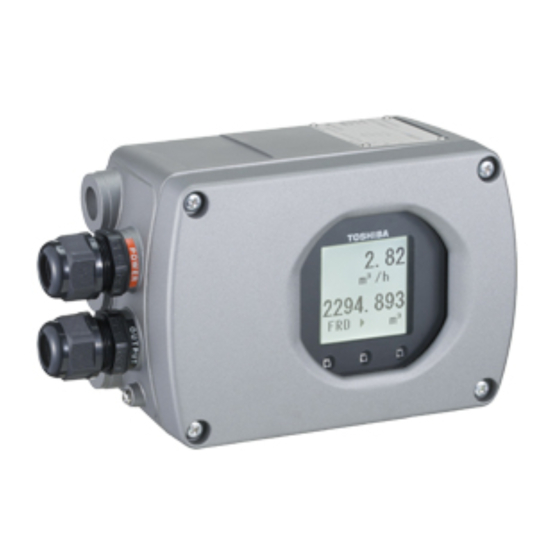
Electromagnetic Flowmeter Converter
NOTES
Before using the equipment, please read this manual carefully and understand the
contents, and then use the equipment correctly.
• NEVER attempt to operate the equipment in any ways that are not described in this
instruction manual.
• After reading this manual, store it with care in a place where it can be referred to
whenever needed.
• Please be sure that this manual is delivered to the personnel who will use this
product.
LF620*B Type, LF622*B Type
INSTRUCTION MANUAL
6 F 8 A 0 9 9 7
Advertisement
Table of Contents
Troubleshooting


Need help?
Do you have a question about the LF620 B Series and is the answer not in the manual?
Questions and answers