Table of Contents
Advertisement
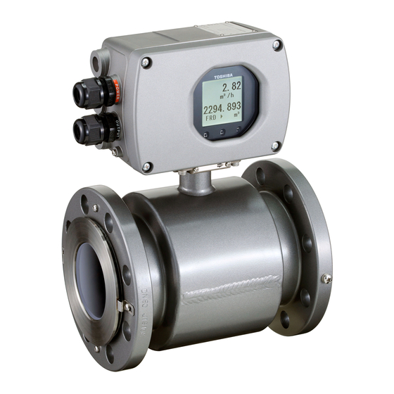
ELECTROMAGNETIC FLOWMETER DETECTOR
NOTES
Before using the equipment, please read this manual carefully and understand the
contents, and then use the equipment correctly.
• NEVER attempt to operate the equipment in any ways that are not described in this
instruction manual.
• After reading this manual, store it with care in a place where it can be referred to
whenever needed.
• Please be sure that this manual is delivered to the personnel who will use this product.
Phone: 800.894.0412 - Fax: 888.723.4773 - Web: www.clrwtr.com - Email: info@clrwtr.com
MODEL LF654
INSTRUCTION MANUAL
6F8A0926
Advertisement
Table of Contents
Troubleshooting

Related Manuals for Toshiba LF654


Summary of Contents for Toshiba LF654
- Page 1 6F8A0926 ELECTROMAGNETIC FLOWMETER DETECTOR MODEL LF654 INSTRUCTION MANUAL NOTES Before using the equipment, please read this manual carefully and understand the contents, and then use the equipment correctly. • NEVER attempt to operate the equipment in any ways that are not described in this instruction manual.
- Page 2 6F8A0926 NOTICE We thank you very much for your purchase of our LF654 series electromagnetic flowmeter detector. Integral type LF654/LF620F Separate type detector LF654 This instruction manual describes the notes on using an electromagnetic flowmeter detector, installation, configuration and maintenance. It is intended for the personnel in charge of installation, operation and maintenance.
-
Page 3: Safety Precautions
6F8A0926 SAFETY PRECAUTIONS Safety signs and labels affixed to the product and/or described in this manual give important information for using the product safely. They help prevent damage to property and obviate hazards for persons using the product. Make yourself familiar with signal words and symbols used for safety signs and labels. Then read the safety precautions that follow to prevent an accident involving personal injury, death or damage to property. - Page 4 6F8A0926 SAFETY PRECAUTIONS Safety Precautions for Installation and Wiring WARNING Do not disconnect while circuit is live unless location is known to be nonhazardous. Live part of electric circuit or a high temperature department can cause explosion. DON’T Do not modify or disassemble the enclosure. Strength degradation and defects of enclosure can cause explosion.
- Page 5 Safety Precautions for Installation and Wiring CAUTION Install a switch and fuse to isolate the Use an appropriate device to carry and install LF654/LF620F and LF654 from mains the LF654/LF620F and LF654. power. Power supply from mains power If this product falls to the ground,...
- Page 6 Warranty and Limitation of Liability Toshiba does not accept liability for any damage or loss, material or personal, caused as a direct or indirect result of the operation of this product in connection with, or due to, the occurrence of any event of force majeure (including fire or earthquake) or the misuse of this product, whether intentional or accidental.
-
Page 7: Handling Precautions
6F8A0926 Handling Precautions To obtain the optimum performance from the LF620F and LF622F converter for years of continuous operation, observe the following precautions. (1) Do not store or install the flowmeter in: ・Places where there is direct sunlight. ・Places where there is snow and ice Infrared switches may not function correctly. - Page 8 6F8A0926 Handling Precautions (continued) (5) If the inside of the converter and detector's terminal box are wetted or humidified, it may cause insulation deterioration, which can result in fault or noise occurrence. So do not conduct wiring in the open air on rainy days. Also, be careful not to wet down the converter and detector's terminal box even in the case of indoor wiring, and complete wiring work in a short period of time.
-
Page 9: Table Of Contents
6F8A0926 Table of Contents SAFETY PRECAUTIONS ····················································································· 2 Handling Precautions ······························································································ 6 1. Product Inspection and Storage ······································································ 9 1.1 Product Inspection ······················································································· 9 1.2 Storage ········································································································ 9 2. Overview ·········································································································· 10 3. Names of Parts ································································································· 11 4. Installation ······································································································· 14 4.1 Notes on Selecting the Installation Location ·············································... -
Page 10: Product Inspection And Storage
Make sure the type and specifications of the flowmeter are in accordance with the ordered specifications. If you cannot find the items listed above or any problem exists, contact your nearest Toshiba representative. 1.2 Strage To store the electromagnetic flowmeter after opening the package, select a storing place as follows and... -
Page 11: Overview
6F8A0926 2. Overview The LF654/LF620F and LF654 electromagnetic flowmeter can be use in the following hazardous (classified) locations. ClassⅠ, Division 2, Groups A, B, C and D, ClassⅡ, Division 2, Groups E, F and G ClassⅢ This product is a converter used for electromagnetic electric flowmeters that measure the volumetric flow rate of conductive fluid using Faraday's law of electromagnetic induction. -
Page 12: Names Of Parts
DI/DO cable 1/2 - 14 NPT Flow direction arrow Ground terminal Ground terminal for detector for converter Detector Grounding ring Flange Figure 3.1.1 Appearance of LF654/LF620F − 11 − Phone: 800.894.0412 - Fax: 888.723.4773 - Web: www.clrwtr.com - Email: info@clrwtr.com... - Page 13 Flow direction arrow Lifting Lugs *Provided for 8 inch and above (200mm to 450mm) Ground terminal for detector Flange Grounding ring Detector Figure 3.1.2 Appearance of LF654 − 12 − Phone: 800.894.0412 - Fax: 888.723.4773 - Web: www.clrwtr.com - Email: info@clrwtr.com...
- Page 14 6F8A0926 3.2 Construction of the terminal blocks 3.2.1 Terminal Block Construction of LF654/LF620F Type For details of the converter, check the LF620F converter's instruction manual. LF620F 3.2.2 Terminal Block Construction of LF654 Type LF622F To signal cable terminal (A,B and G) To excitation cable terminal(X,Y and E) Don’t connect wiring to this terminal.
-
Page 15: Installation
Install a switch and fuse to isolate the Do not modify or disassemble the LF654/LF620F and LF654 from mains power. LF654/LF6*0F and LF654 unnecessarily. Power supply from mains power Modifying or disassembling this product... -
Page 16: Notes On Selecting The Installation Location
6F8A0926 4.1 Notes on Selecting the Installation Location Avoid places within the immediate proximity of equipment producing electrical interference (such as motors, transformers, radio transmitters, electrolytic cells, or other equipment causing electromagnetic or electrostatic interference). Avoid places where excessive pipe vibration occurs. Avoid places where fluid is pumped in a pulsating manner. - Page 17 6F8A0926 (2) Preventing an Empty Pipe Condition Fix the relevant pipes installed on both sides of the detector by attaching fittings, etc. to support the pipe. By supporting the pipes, not only the pipe vibration is reduced but also the damage to the pipes by the electromagnetic flowmeter's weight and the fluid mass (see Figures 4.2 and 4.3).
- Page 18 6F8A0926 4.2.2 Installation Procedure To mount the LF654, place it between the upstream and downstream pipe flanges and tighten it with flange bolts and nuts. See Figure 4.4 and follow the procedure below: Insert two lower mounting bolts through the clearance holes in the upstream (or downstream) pipe flange.
- Page 19 6F8A0926 Table 4.1 Bolt length and Nut tightening torque ANSI class 150 Machine Bolts Tightening Meter size torque Length P.C.S Diameter [N・m] *1 [inch] 15mm 1/2” 1/2” 2” 7 to 9 25mm 1” 1/2” 2.16” 14 to 17 32mm 1 1/4” 1/2”...
- Page 20 (b) Meter size 15mm to 150mm (1/2" to 6") (a) Meter size 200mm to 450mm (8" to 18") Hanging hooks are not provided Hanging hooks are provided Figure 4.5 Transportation of LF654 flowmeter detector − 19 − Phone: 800.894.0412 - Fax: 888.723.4773 - Web: www.clrwtr.com - Email: info@clrwtr.com...
-
Page 21: Piping Connections
A minimum of 1D (diameter) length of upstream straight pipe from the flange is required to maintain the performance specification. NOTE The test results were obtained and demonstrated at Toshiba admitted flow calibration facility. − 20 −... - Page 22 6F8A0926 (2) Pipe Orientation The detector may be installed in horizontal, vertical or sloping pipe runs as shown in Figure 4.6. However, except for horizontal installation, fluid should flow from lower to upper directions. If no air bubble, Vertical down flow application are acceptable under pressured piping conditions.
- Page 23 6F8A0926 (3) Flow Direction Install the detector in accordance with the flow direction arrow on the detector. See Figure 4.8. Flow direction arrow Figure 4.8 Flow direction arrow on the detector (4) Preventing an Empty Pipe Condition Design an upright pipe run (Figure 4.9) or sufficient head pressure (Fig. 4.10) at the downstream detector outlet if there is a possibility of the detector pipe becoming emptied.
-
Page 24: Grounding
DON’T may cause electric shock. DON’T (1) Grounding of the LF654/LF620F type Ground as shown in Figure 4.11. Make the grounding wire as short as possible. Use grounding LF620F wire material of IV wire 5.5mm or more. - Page 25 • If the piping material is non-conductive, perform grounding grounding wires to the both ends of the piping flange. resistance 100Ω or less. Figure 4.13 Grounding the LF654 Type Detector − 24 − Phone: 800.894.0412 - Fax: 888.723.4773 - Web: www.clrwtr.com - Email: info@clrwtr.com...
-
Page 26: Wiring
3S8A2677 (Refer to Appendix 1 and 2.). Unsuitable conduit connections for hazardous location can cause explosion. CAUTION Install a switch and fuse to isolate the LF654/ Turn off mains power before conducting wiring LF620F and LF654 from mains power. work. -
Page 27: Cables
6F8A0926 Notes on wiring CAUTION (1) Select the cable runs away from electrical equipment (motors, transformers, or radio transmitters) which causes electromagnetic or electrostatic interference. (2) Deterioration of flowmeter circuit insulation occurs if the converter interior or cable ends get wet or humidified. - Page 28 When replacing the flow rate signal cable and excitation cable, also refer to the instruction manual of the relevant detector. Order the detector terminal box cover packing from Toshiba. − 27 −...
-
Page 29: Wiring
6F8A0926 5.4 Wiring 5.4.1 Terminal Treatment of Cables Follow the procedures below to treat the terminals (at the converter side) of various cables and install the cables to the terminal block. Use appropriate cables based on the description in Section 5.1 "Cables." Crimp a round type insulated crimp-type terminal to the end of the cables. - Page 30 6F8A0926 (3) Connecting the input signal cable Strip the sheath from the end of each conductor of a 2-core individually shielded cable as shown in Figure LF622F 5.4. Twist those shields and cover them with a thermal contraction tube or vinyl tube not to make contact with the case or core wires.
- Page 31 6F8A0926 5.4.2 Cable Connection Connect and install the terminal-treated cables to the terminal block. *Connect the cables to the terminal block securely. A loose connection may cause incorrect measurement. After connecting a cable, try to pull it to check whether it has been connected securely. (1)Referring to combined converter's manuals of "Connections and Grounding", connect each cable to the terminal block.
-
Page 32: Operation
6F8A0926 6. Operation CAUTION Do not touch the terminal board when Do not touch the main body when high power is supplied. temperature fluid is being measured. Touching the terminal board The fluid raises the main body when power is supplied can temperature and can cause burns. -
Page 33: Maintenance And Troubleshooting
3S8A2676, 3S8A2677 (Refer to Appendix 1 and 2.). Unsuitable conduit connections for hazardous location can cause explosion. CAUTION Do not conduct wiring work when Do not touch the LF654/LF620F and power is applied. LF654 main body when high temperature fluid is being measured. -
Page 34: Maintenance
In order to use the display unit stably for a long time, it is preferable to replace it early. For inspection and replacement, please contact your nearest Toshiba representative. Power supply unit (also used for excitation board) Electronic components deteriorate faster when the ambient temperature is high. -
Page 35: Troubleshooting
6F8A0926 7.2 Troubleshooting If a problem occurs while using the LF654/LF620F and LF654, follow the flowcharts described below. You may find a way to solve the problem. The flowcharts are based on three symptoms (1) to (3). If you cannot solve the problem, contact your nearest Toshiba representative. - Page 36 Is accuracy calculated as follows? Calculate as shown on the left. (Measured flow rate)-(Actual flow rate) × 100% Actual flow rate Contact your nearest Toshiba representative. − 35 − Phone: 800.894.0412 - Fax: 888.723.4773 - Web: www.clrwtr.com - Email: info@clrwtr.com...
- Page 37 Note 1: If the detector tube is not filled with operating fluid, the flow is indefinite and Contact your nearest Toshiba measurement is impossible. Be sure to fill representative. the detector tube with operating fluid before starting measurement.
-
Page 38: Principle Of Operation
Square-Wave Excitation Figure 8.1 Principle of Operation The LF654/LF620F and LF654 uses the square-wave excitation method, which provides long-term stable operation. With square-wave excitation, the LF654/LF620F and LF654 offers reliable measurement without being affected by electrostatic or electromagnetic interference, or electrochemical polarization between the electrodes and the fluid to be measured. -
Page 39: Specifications
System accuracy: Accuracy: ±0.2 % of Rate* * This pulse output error result is established under standard operating conditions at Toshiba admitted flow calibration facility. (NIST Traceable). * Individual meter measurement error may vary up to ±0.5% of Rate at 1.64 ft/s (0.5m/s) or more and ±0.3% of rate ±0.039 inch/s (1mm/s) at 1.64 ft/s (0.5m/s)or less. - Page 40 6F8A0926 Coating: Polyurethane resin coating (std.) gray colored Structure: IP67 and NEMA 4X ( Standard ) Option: IP 68 and NEMA 6P Submersible type Specification of Submersible type Structure: Separate type only (except PFA lining is available.) LF622F Range of underwater: within 15m Coating: tar epoxy resin, thickness 0.5 mm Executed evaluation test: It is confirmed that it leaves for 48hours every depth 15m, and moisture doesn't infiltrate internally.
- Page 41 6F8A0926 Flow and calibration velocity range: specified. It calibration by standard Range shown in the table below when Range is not It calibration when there is specification by flowing quantity Range in which the customer is specified. Is this specification Range flowing quantity of Table 9.1. Please confirm becoming in the upper bound value from the flow velocity chart.
- Page 42 6F8A0926 To select the meter size: See Table 9.2 to find meter sizes within the velocity of 0.3 to 39.4 ft/s (0.1 to 12m/s) for a specified full-scale (measuring range high limit) flow. Select one that has its full-scale velocity between 3.0 and 10 ft/s (1 and 3m/s). Note: Make sure the full-scale flow rate used for the final planning stage stays within 39.4 ft/s (12m/s) in terms of flow velocity.
-
Page 43: Type Specification Code
–: Not available Note1: Range of ambient temperature is from -4 °F to 140 °F (-20 to +60C). Note2: Consult Toshiba before ordering when choose materials at the wetting parts. Note3: Separate type detector only. Note4: Separate type detector only. Specifying the code “C”, indicate the length of cables from 1 to 300m 1 meter increments. - Page 44 6F8A0926 Table 9.4 Type Specification Code (Exciting Cable and Signal Cable) LF622F Model Specification Code Description 1 2 3 A C C Dedicated preformed cable Nominal cross-sectional area of Exciting cable (Note 1) 1.25 mm² 2 mm² Nominal cross-sectional area of Signal cable (Note 2) 0.75 mm²...
-
Page 45: Outline Dimensions
6F8A0926 10. Outline Dimensions 10.1 Outline dimensions of LF654/LF620F (1) Meter size of 1/2 inch to 8 inch (15mm to 200mm) LF620F Hanging hook *2 Meter size L1 inch (mm) L3 inch (mm) Mass *1 L2 inch (mm) Toshiba length... - Page 46 (2) Meter size of 10 inch to 18 inch (250mm to 450mm) LF620F Meter size L1 inch (mm) L3 inch (mm) Mass *1 L2 inch (mm) inch Toshiba length ISO length ANSI 150 10" 13.87 (350) 17.72 (450) 13.15 (334) 21.14 (537) approx.
- Page 47 6F8A0926 10.2 Outline dimensions of LF654 (1) Meter size of 1/2 inch to 8 inch (15mm to 200mm) LF622F Hanging hook *2 Meter size L1 inch (mm) L3 inch (mm) Mass *1 L2 inch (mm) inch Toshiba length ISO length ANSI 150 1/2"...
- Page 48 (2) Meter size of 10 inch to 18 inch (250mm to 450mm) LF622F Meter size L1 inch (mm) L3 inch (mm) Mass *1 L2 inch (mm) inch ISO length ANSI 150 Toshiba length 10" 13.87 (350) 17.72 (450) 11.85 (301) 19.84 (504) approx. 205 12" 15.75 (400) 19.69 (500) 13.35 (339)
- Page 49 6F8A0926 Appendix 1 1-1 A system block diagram for LF654/LF620F − 48 − Phone: 800.894.0412 - Fax: 888.723.4773 - Web: www.clrwtr.com - Email: info@clrwtr.com...
- Page 50 6F8A0926 1-2 A system block diagram for LF654 − 49 − Phone: 800.894.0412 - Fax: 888.723.4773 - Web: www.clrwtr.com - Email: info@clrwtr.com...
- Page 51 6F8A0926 Write down the address and phone number of the distributor from which you purchased this product, the product code, SER.NO. and so on. Distributor Address Name Phone number ( ) − Product code SER.NO. − 50 − Phone: 800.894.0412 - Fax: 888.723.4773 - Web: www.clrwtr.com - Email: info@clrwtr.com...
Need help?
Do you have a question about the LF654 and is the answer not in the manual?
Questions and answers